

Linear Actuators With Controllers for Synchronized Motion
When two or more actuators support the same moving structure, controller selection becomes a coordination problem rather than a simple channel-count choice. ServoCylMotion routes synchronized projects through the documented YK-06, YK-08 and YK-10 controller families, then reviews the actuator, load, wiring, power and operating sequence as one system.
The current product record identifies synchronized two-, three- and four-channel models. It does not publish a universal synchronization tolerance, sensor architecture or feedback method; those details must be confirmed for the intended configuration.
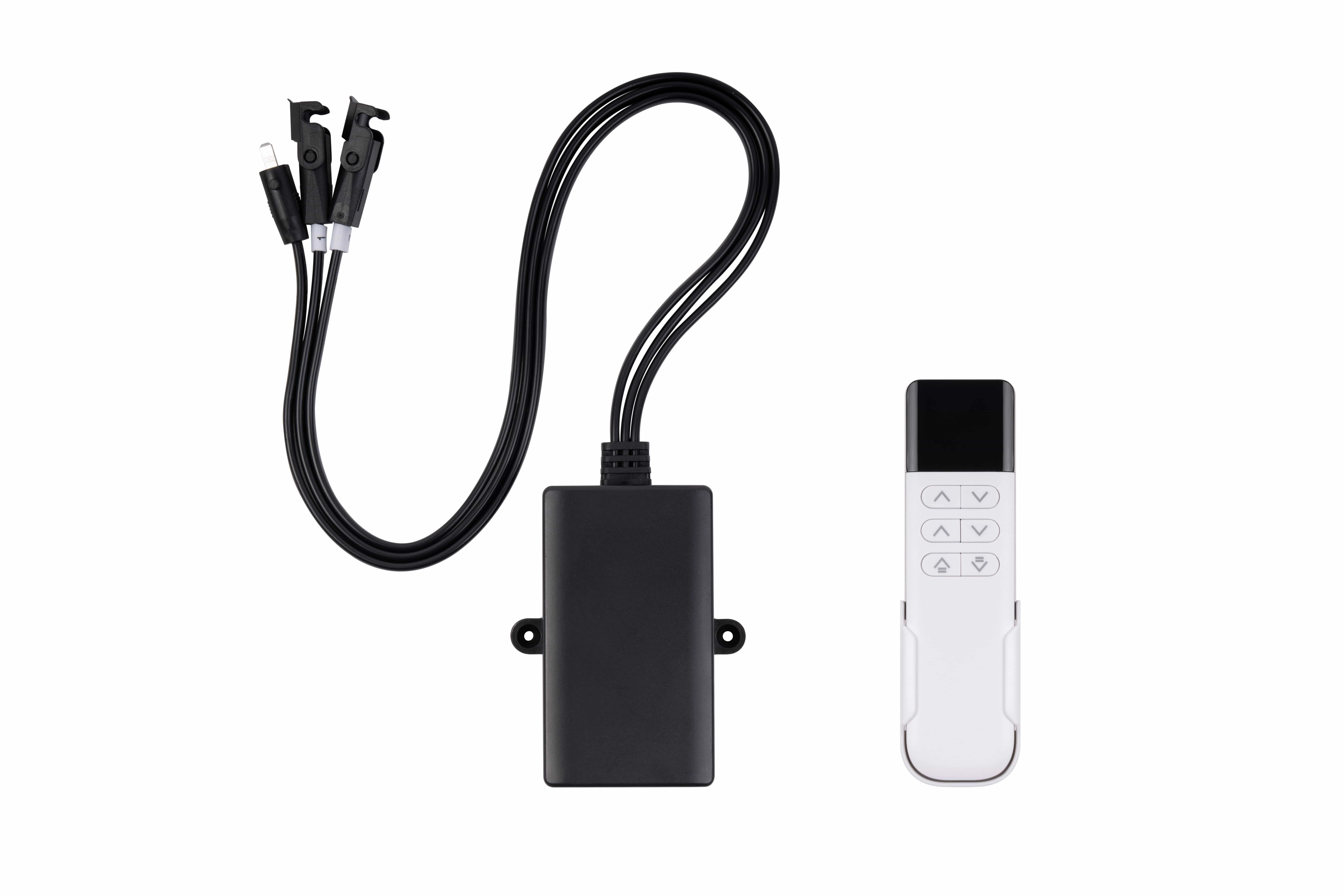
Match Motor Count to the Documented Synchronized Controller Route
Use channel count only as the first routing input. Final approval still depends on the required motion relationship, actuator choice, load distribution, reset behavior, power and wiring.
YK-06 synchronized route
Use as the documented starting point for paired actuators supporting one coordinated mechanism, such as two-leg desk frames or other paired-motion equipment.
Synchronized Motion Is More Than “Plug In More Motors”
Coordinated axes need one explicit motion relationship and a defined recovery path. The controller cannot compensate for a poorly defined mechanical system, unequal loading assumptions or unknown actuator compatibility.
One moving structure
Define which actuators support the same structure and whether they must maintain coordinated travel.
Matched motion hardware
Review actuator model, stroke, speed, load and mounting together rather than mixing parts by nominal voltage alone.
Coordinated channels
Choose the documented synchronized channel route, then confirm the actual control logic and ordered interfaces.
One configuration
Confirm power supply, connectors, cable routing, pinout and reset behavior before production release.
Carry the Motion Relationship Through Five Engineering Gates
Every gate should reduce uncertainty rather than merely move the project forward.
Motion relationship
Which axes move together, what load each axis sees, and what happens at start, stop and end positions?
Actuator set
Confirm model, stroke, loaded speed, mounting and mechanical geometry for every connected axis.
Controller channels
Map the system to YK-06, YK-08 or YK-10 as the documented synchronized starting route.
Power + interfaces
Review supply, connectors, cable length, pinout, operator interface, reset and expected sequence.
Application criteria
Approve the sample only against named mechanical and operating criteria for the intended equipment.
Use Synchronization Where the Mechanism Actually Requires It
Two motors do not automatically require synchronized motion. Independent adjustable-bed zones, for example, can have a different control requirement from two columns supporting one desk surface.
2 / 3 / 4-leg coordinated lift
YK-06, YK-08 and YK-10 map to two-, three- and four-motor synchronized desk architectures in the current product record.
Standing desk systemsShared or independent movement
Define whether actuators support the same moving surface or independent zones before selecting the control route.
Adjustable bed systemsProject-defined coordination
For lifting platforms or other multi-axis equipment, send the mechanism drawing and required motion relationship rather than choosing by motor count alone.
Custom motion capabilitiesSend the Inputs That Change Synchronization Feasibility
If some values are unknown, send the mechanism drawing and target behavior. Engineering can identify which missing values matter first.
Multi-Motor Synchronization FAQ
Keep the documented controller route separate from project-specific synchronization performance.
Which ServoCylMotion YK controllers are documented for synchronized multi-motor operation?
The current local product data identifies YK-06, YK-08 and YK-10 as synchronized two-, three- and four-channel models respectively.
Does every two-motor mechanism need synchronization?
No. Two actuators can operate independent zones or can support one shared structure. State the required motion relationship first; channel count alone does not define the correct control logic.
What synchronization tolerance is guaranteed?
No universal numeric tolerance is published in the current controlled local product data. If your equipment requires a specific tolerance, define it as an acceptance requirement and confirm feasibility for the complete actuator/controller configuration.
What feedback or sensor system is used?
The current local page data does not establish one universal feedback architecture or sensor type for every synchronized configuration. Confirm this during engineering review when your project depends on a particular feedback method.
Can wireless behavior, cables and motion curves be customized?
The current YK product data lists wireless frequency/pairing, cable length, connector type, receiver mounting, button/icon treatment and motor speed/acceleration/deceleration curve adjustment among reviewable customization areas. Exact availability must be confirmed against the chosen model and project.
Define the mechanism first. Then select the coordinated control route.
Send motor count, load distribution, stroke, target speed, mounting geometry, desired motion relationship, reset behavior, power, connectors, cable lengths and acceptance criteria.