

ServoCylMotion power cable and connector reference — representative customization object
Capabilities / Electrical interface engineering

Custom Actuator Power Cable Engineering for OEM Systems

Define the cable as part of the motion system—not as a length or connector choice in isolation. The assembly has to match the connected devices, electrical load or feedback, connector and pin map, and installation duty at the same time.

Controlled electrical path / project definition Source → cable architecture → mating device
Source Harness Device
01 / Architecture Mains / motor / signal / combined
02 / Connector Mating family + keying
03 / Pinout Contacts + polarity + feedback
04 / Integration Routing + identity + release
/ 01 / Cable function switcher

Choose the electrical job before defining the assembly.

“Actuator cable” can describe four different system paths. Switch the function to see which interfaces and release inputs become decision-critical.

System path / mains-side input Power source → powered unit
Source
Wall source
Define Destination + length
Interface Inlet + region
Device
Powered unit
Mode 01 / Mains-side input

Wall source to power supply or powered control unit.

Confirm the powered device, inlet, destination and required length before release.

Use when The requirement is the input side of the powered system.
System path / motor power Power stage → actuator motor
Stage
Controller / power stage
Load Voltage + current
Release Polarity + length
Motor
Actuator motor
Mode 02 / Motor-power cable

Controller or power stage to the actuator motor.

Review voltage, current, conductor count, polarity and length as one electrical path.

Primary risk Treating gauge or length as an isolated choice without the actual electrical load.
System path / signal + feedback Sensor → controller
Sensor
Actuator feedback
Signal Feedback + pinout
Routing Conductors + shielding
Control
Controller
Mode 03 / Signal or feedback

Actuator sensor to the control system.

Define feedback type, pinout, conductor count, and any routing or shielding requirement before approval.

Identify Hall, limit, potentiometer, encoder or other feedback used by the project.
Do not assume Every signal cable requires the same shielding or routing treatment.
System path / combined assembly Power + feedback → one harness
Motion
Actuator system
Power Current + contacts
Signal Pin map + capacity
Control
Control system
Mode 04 / Combined assembly

Motor power and feedback inside one harness.

Review current, signal type, pin map, connector capacity and noise-control needs together.

Define Which contacts carry power and which carry feedback.
Release Approve the complete connector and pin-map definition, not only the outer cable.
/ 02 / Electrical definition

Length, current, gauge and connector definition belong in the same review.

Longer conductors add resistance. Under load, voltage loss or heating can become relevant when conductor size, joints or connector resistance are not appropriate. There is no single published maximum length that applies to every actuator system.
01 System voltage Provide nominal voltage so the cable is reviewed inside the actual electrical architecture.
02 Operating / peak current Provide expected current when known; it is an input to conductor-size and connection review.
03 Requested length State overall and branch lengths. Length is not treated as an isolated customization option.
04 Conductors + feedback State conductor count, feedback type and existing wire size when replacing a current design.
05 Connector A / B Lock family, gender, keying, mating part and termination at both ends.
06 Pin map Control pin assignment, polarity, wire colors and feedback contacts against the approved drawing.
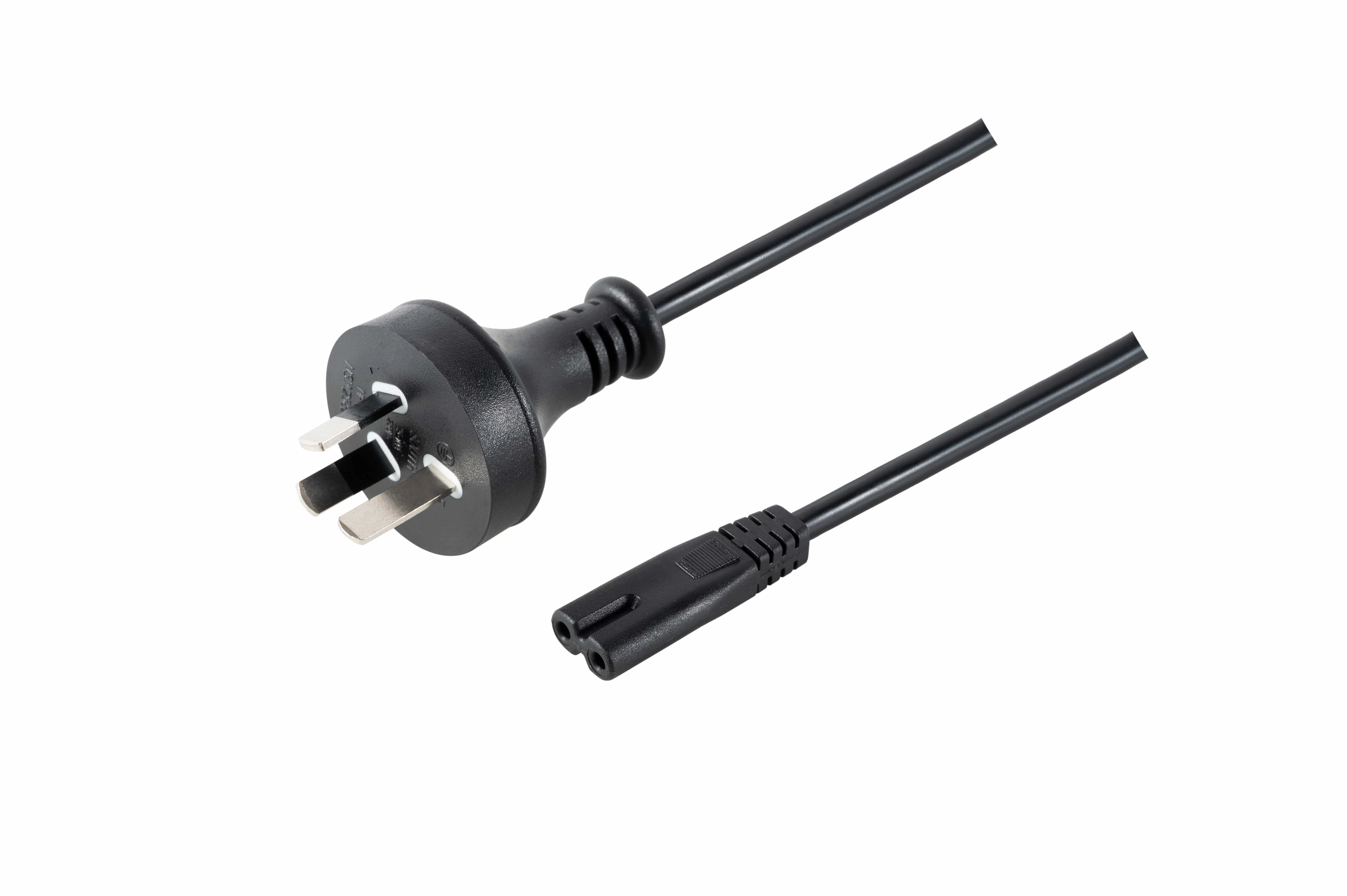
ServoCylMotion mains-side power cord with molded connector
Mains-side cable object / connector definition reference
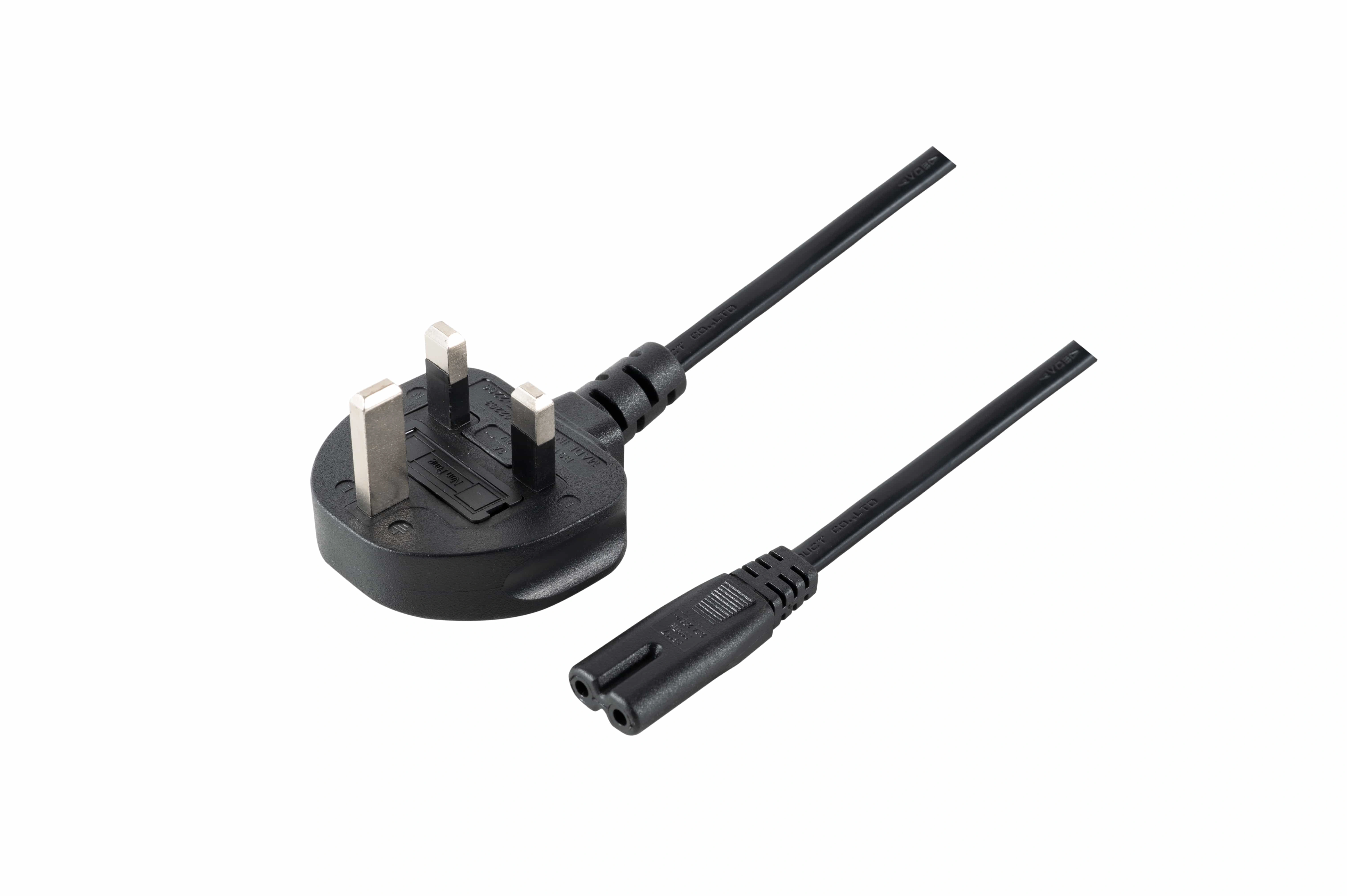
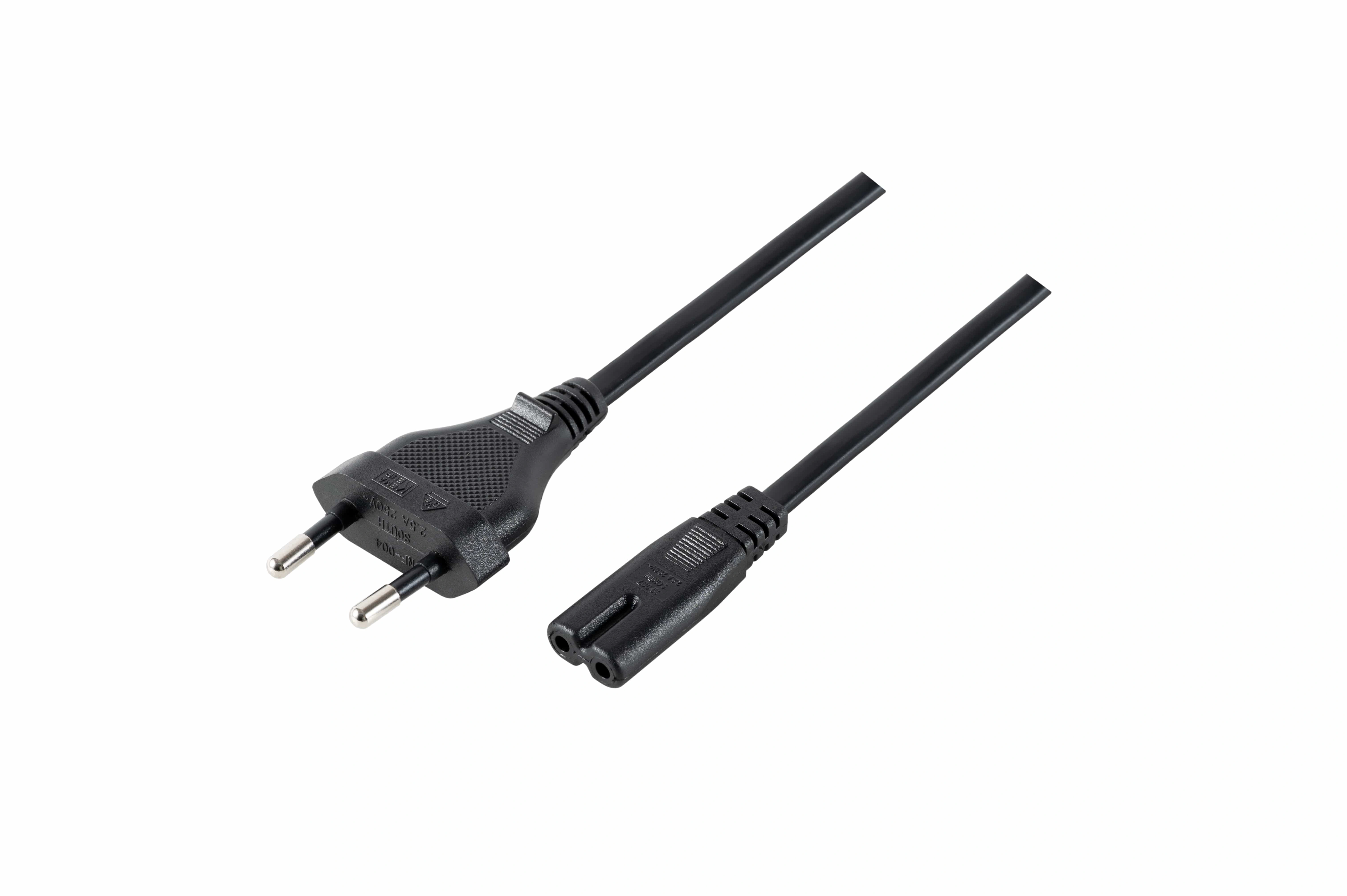
ServoCylMotion European mains-side cable with equipment connector
Connector geometry / representative cable family reference
/ 03 / Connector + pin map

Mechanical fit is not electrical compatibility.

The mating device and contact functions have to be controlled at both ends. Connector modification and custom molded interface review are project-review categories; final compatibility belongs to the actual mating hardware and approved pin map.

Control Define Why Release input
A Device identity Correct mating context Actuator / control / supply IDs
B Connector family Mechanical + locking fit Family / gender / keying
C Power contacts Electrical path definition Voltage / current / polarity
D Feedback contacts Signal architecture Type / pin assignment
E Branches Harness topology Branch lengths / endpoints

Approve the mating part and pin map together. A connector that fits mechanically is not automatically wired correctly for the control system.

/ 04 / Routing + installation duty

Separate the electrical architecture from the cable’s mechanical job.

Power and feedback may be separate or combined depending on current, signal type, connector capacity, routing and electrical-noise conditions. Installation duty then adds a second decision: fixed, occasionally moved, or repetitively flexed.
Fixed State enclosure routing, service access, bend space and environmental exposure.
Occasional Describe where movement occurs and how the cable and termination are supported.
Repetitive Provide motion path, bend constraints, vibration, abrasion, moisture and temperature conditions for review.
System compatibility review →
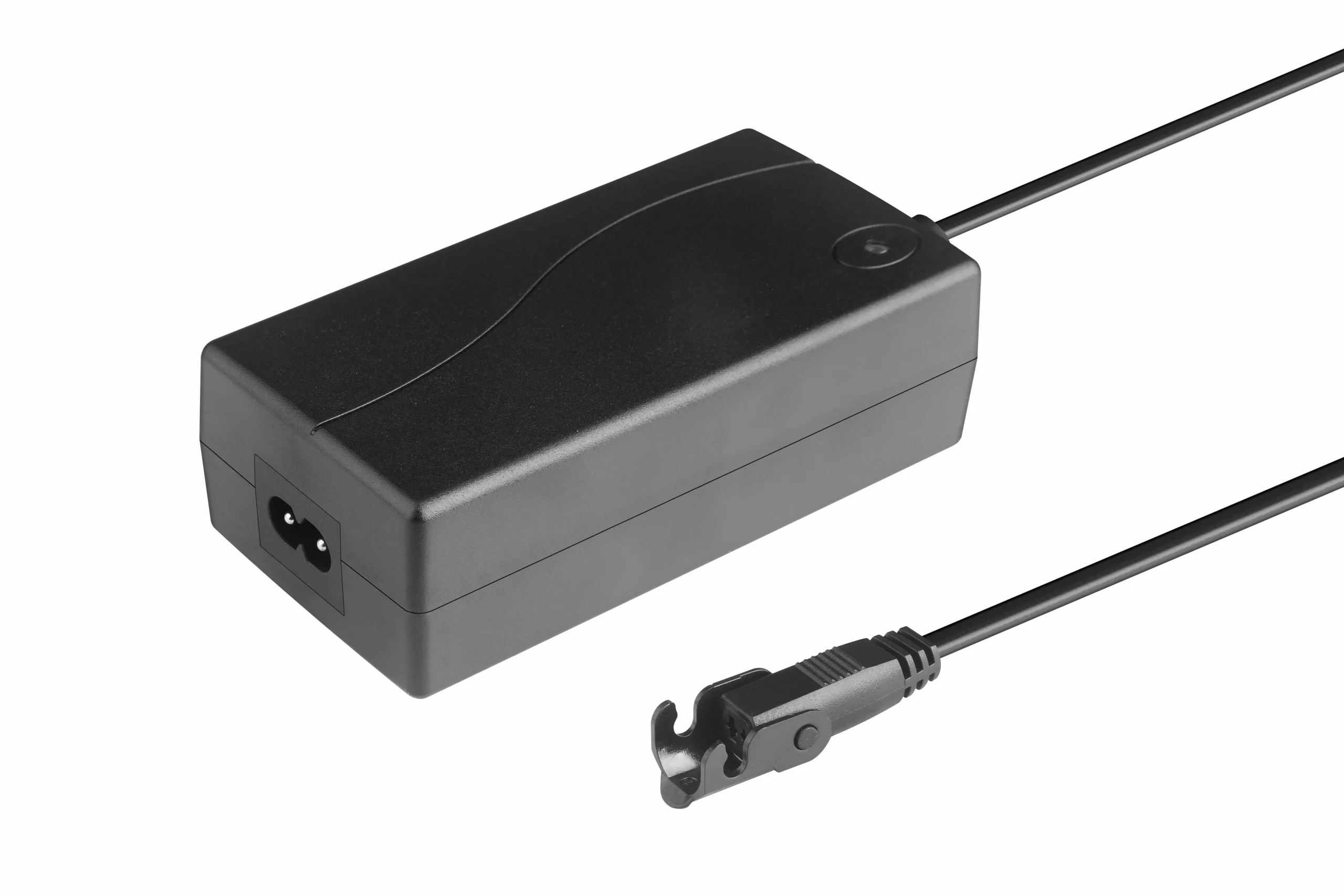
ServoCylMotion desktop power supply and connected power interface reference
System power component / cable interface context
/ 05 / Customization scope

Define what changes—and what still requires project review.

The current project record supports these review categories. They are configuration categories, not unlimited availability promises.

01 Cable length Match routing, service access, electrical load and installation geometry. Project review
02 Wire gauge Review conductor sizing against voltage, current, length and connection conditions. Project review
03 End termination Review equipment-side connector or another approved termination. Interface lock
04 Custom molded interface Evaluate a project-specific molded connector where suitable. Interface lock
05 Identification Review labels, customer part numbers and barcode requirements. OEM release
06 Packaging Review bulk or individual project pack-out. OEM release
/ 06 / Engineering review checklist

Release the cable as a controlled system interface.

Bring the electrical load, device identity, connector definition, routing and OEM release requirements into one review so engineering and procurement are looking at the same assembly.

01 Cable function Mains, motor, signal, or combined
02 Mating devices Actuator, controller, supply, other IDs
03 Electrical load Nominal voltage and expected current
04 Conductors Count and feedback type
05 Connector A / B Family, gender, keying, mating part
06 Pin map Pinout, polarity, wire colors, drawing
07 Length Overall and branch lengths
08 Routing Fixed, occasional, repetitive flex
09 Environment Temperature, vibration, abrasion, moisture, dust
10 OEM identity Part number, barcode, label, marking
11 Packaging Bulk, individual, other pack-out
12 Project volume Prototype and expected production quantity
13 Validation Inspection, test, compliance, documentation criteria
I/O
OEM integration advantage

Reduce ambiguity before the cable becomes a production BOM item.

A requirements-led cable review keeps electrical load, connector fit, pinout, routing and OEM part identity aligned. Defining those items together helps engineering and procurement release a cleaner cable BOM and reduce avoidable field rework before production approval.

/ 07 / FAQ

Specify the interface—not just the cable length.

Exact ratings and available constructions remain project-specific. Start with devices, electrical function, mating interface and installation duty.

What information is needed to specify a custom actuator cable?

Provide the devices being connected, cable function, voltage/current information, conductor count, feedback type, connectors and pinout, target length, routing conditions, environment, quantity, and identification or documentation requirements.

Can the cable length be customized?

Yes, custom length review is supported. Approval should consider electrical load, conductor size, routing, connectors, and signal architecture rather than length alone.

Does a longer cable automatically need a larger wire gauge?

No. It may require a conductor-size review depending on current, system voltage, route length, connector resistance, allowable loss, and thermal conditions.

Can motor power and feedback share one cable?

Some systems combine them and others keep them separate. The decision depends on current, feedback type, connector pin count, shielding needs, and control architecture.

Can the connector and pinout be customized to my control box?

Connector changes and custom molded interfaces are supported as project-review categories. Supply the mating connector, pin map, polarity, and control-box identification.

Is a fixed cable suitable for repetitive flexing?

Not by default. Repetitive motion changes the mechanical requirements for the cable and termination. State the motion path and bend constraints during review.

Can labels, part numbers, barcodes, and packaging be customized?

The current project record supports customer identification and packaging review, including part-number/barcode labeling and project-specific pack-out.

Cable engineering intake

Send Your Cable Requirements

Send device part numbers, voltage/current information, connector and pinout, target length, routing conditions, environment, quantity, labeling, packaging, and required validation documents.
Send cable requirements →
Product image