

Standing Desk Actuator Systems for Commercial Desk Programs
A standing desk actuator is one part of a complete motion platform. For desk manufacturers and frame integrators, the production system also includes structural guidance, controller, power source, wiring, mounting interfaces, and the frame geometry that carries the load.
The same applies when a project starts from a standing desk motor requirement or an existing standing desk frame . Motor count alone does not define a production-ready solution. Moving load, travel, loaded speed, duty pattern, synchronization behavior, installation space, and service requirements need to be reviewed together.
Start With the Motion-System BOM
A component should not be released only because its nominal voltage, force, or channel count appears suitable.
| System layer | Typical scope | Define before selection |
|---|---|---|
| Motion | Lifting columns or guided actuators, motor and transmission | Lifting points, moving load, travel, loaded speed, mounting |
| Control | Multi-channel controller, feedback interface, handset or panel | Channel count, synchronized or independent motion, reset and fault behavior |
| Power | DC supply, mains interface, connectors | Input market, current demand, startup load, simultaneous motors |
| Frame interfaces | Rails, cross-members, feet, brackets, top attachment | Layout, span, mounting holes, stiffness target, service access |
| Cabling | Motor, feedback, control, and power leads | Length, pinout, routing, bend allowance, strain relief |
| Validation | Functional, stability, thermal, cable, and life checks | Test load, duty profile, acceptance criteria |
Match the Architecture to the Frame Layout
Frame layout changes the number of lifting points, load paths, controller channels, wiring, and synchronization requirement. Select a table row to hand the state back to the architecture diagram.
| Platform | Motion-system implication | Local controller reference |
|---|---|---|
| Two-leg | Two lifting points share one moving surface | YK-06 is documented as a synchronized two-channel model |
| Three-leg corner | Three points coordinate around an asymmetric surface | YK-08 is documented as a synchronized three-channel model |
| Four-leg | Four points increase channel and load-distribution complexity | YK-10 is documented as a synchronized four-channel model |
| Bench or special layout | Channel grouping depends on the mechanical architecture | Define the sequence before controller selection |
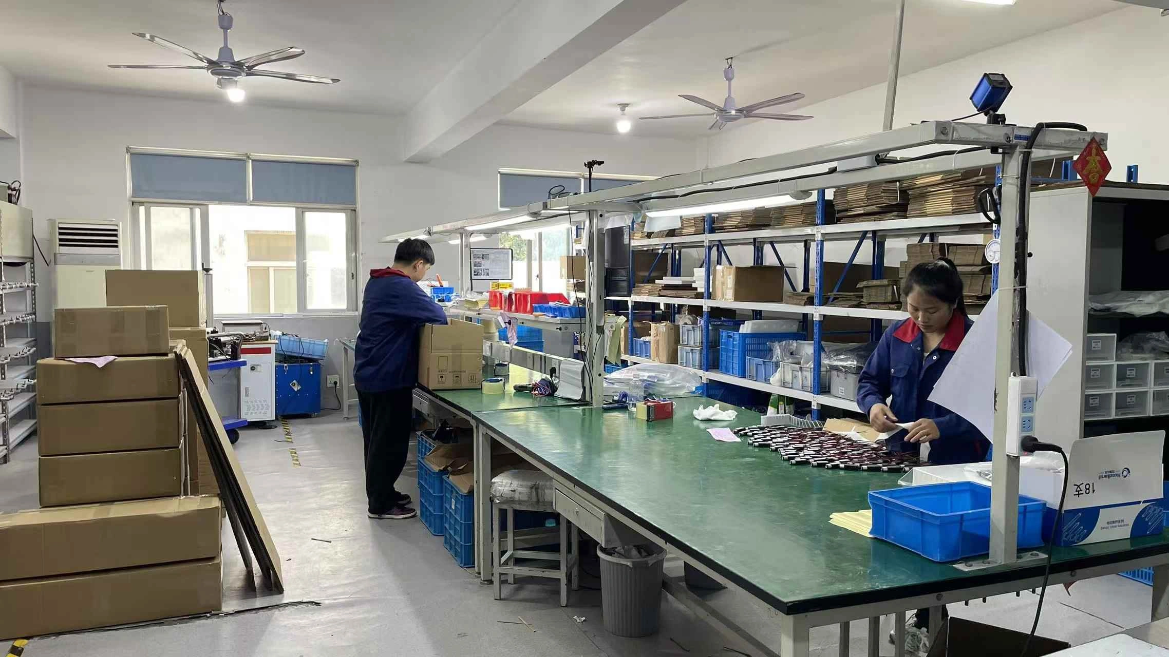
Translate frame architecture into a buildable motion system.
Architecture selection defines how many lifting points must coordinate and which interfaces need review. Production imagery adds manufacturing context, while the released frame geometry, actuator interfaces, controller, wiring, and validation plan remain the governing evidence.
Define the Real Operating Point
Before comparing the linear actuator portfolio , provide the conditions the motion system must actually handle.
ServoCylMotion’s PT and ZT families are locally documented as 29V actuator platforms. They should be treated as candidate motion families only after load, geometry, guidance, speed, travel, and control requirements are checked. Family maxima should not be combined into one assumed configuration.
Match Synchronization, Power, and Wiring
Multi-point lifting requires the controller, feedback method, actuator characteristics, wiring, and mechanical platform to work together.
Synchronization and recovery
Define initialization, reset behavior, response to a stalled or disconnected channel, and recovery after power interruption.
Review multi-motor synchronization →29V is a starting condition, not approval
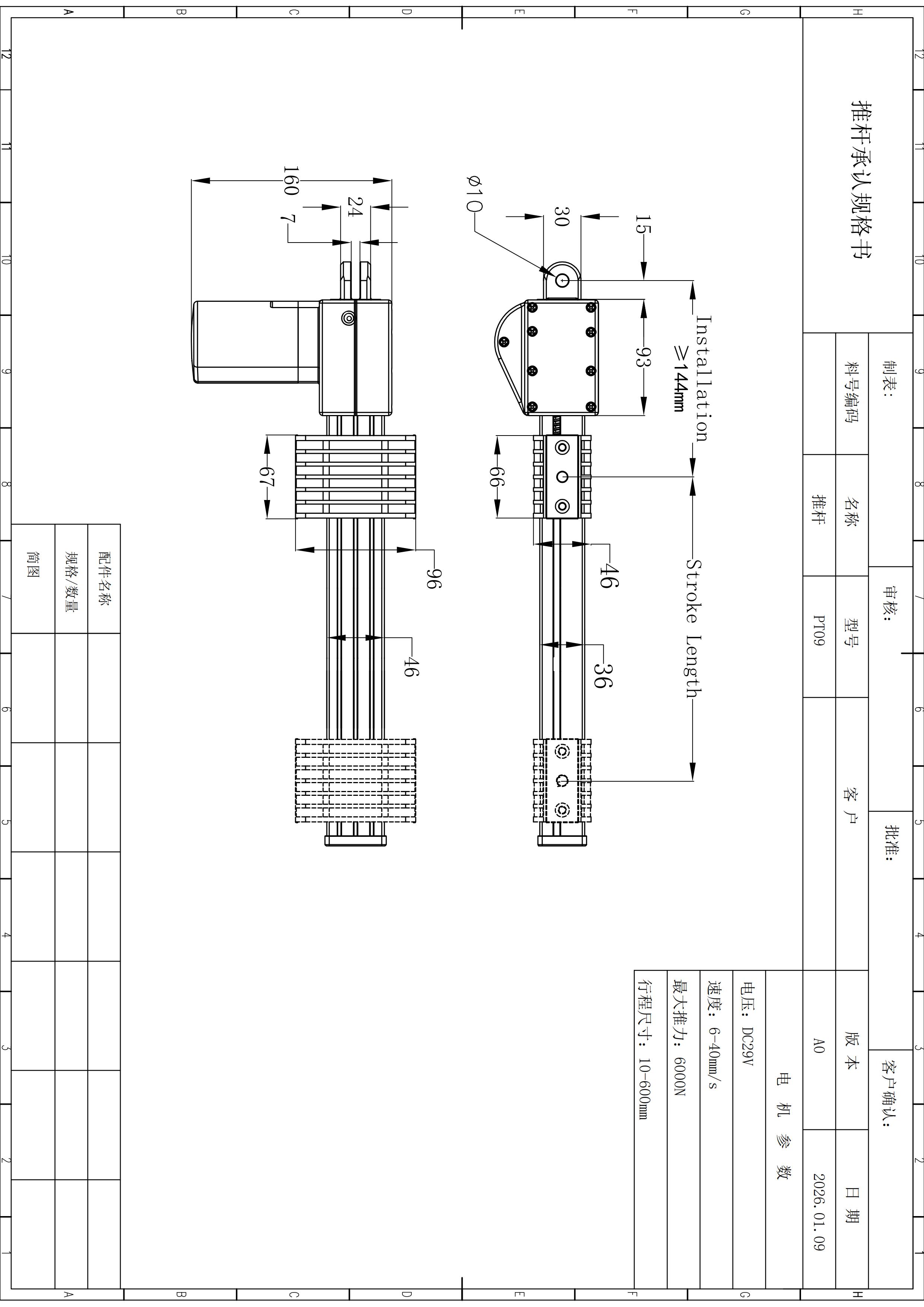
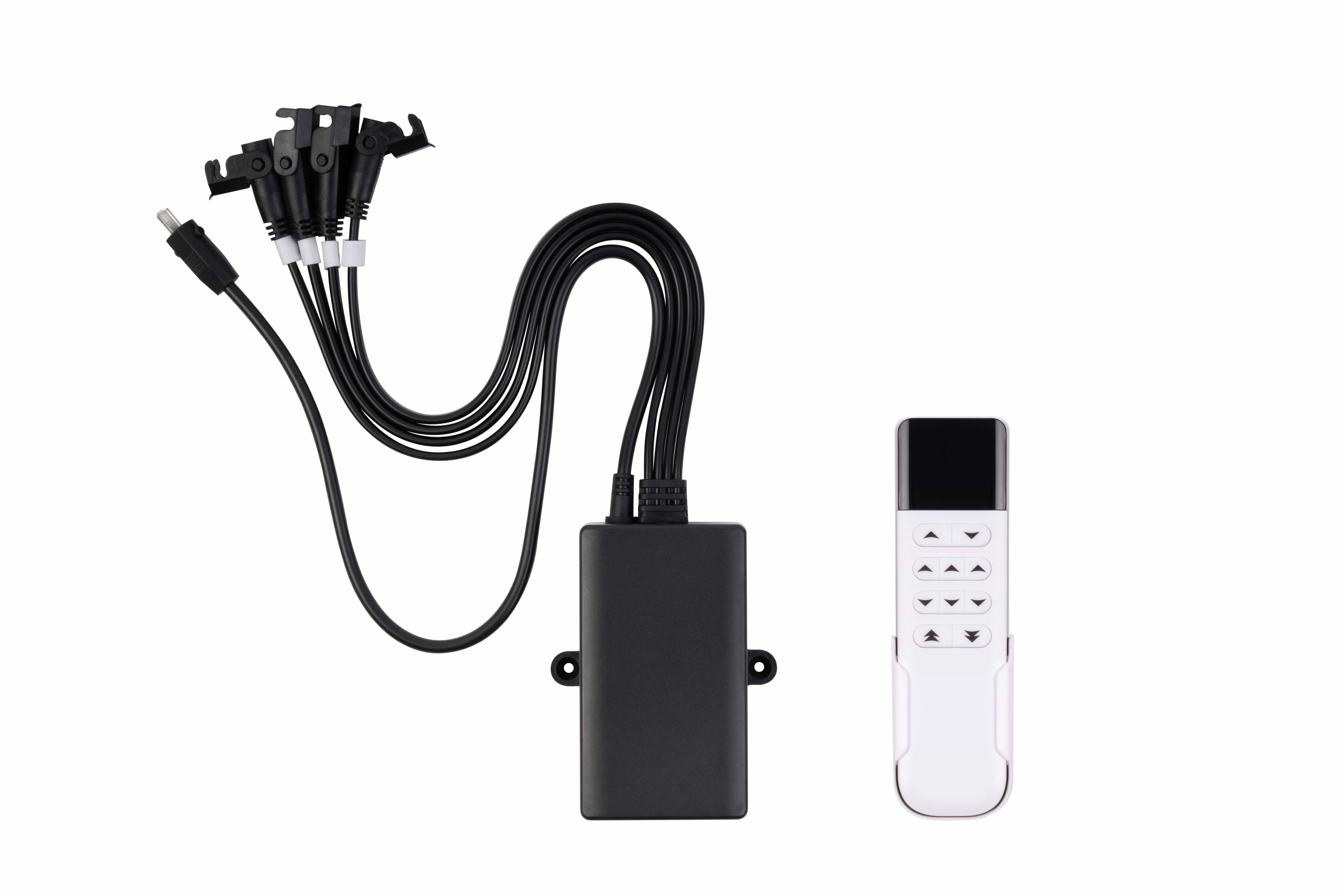
The local YK family is documented around DC 29V and a 60–120W family platform. ServoCylMotion also records multiple 29V power supply options. Shared voltage does not establish compatibility: startup current, simultaneous motor demand, connector and polarity, controller interface, cabling, and the selected actuator configuration still need to match.
Review 29V power supplies →Inspect motion and control components without assuming compatibility.
These local product images are design-review references. Final matching still depends on the verified operating point and interfaces.
Treat Stability and Mounting as System Requirements
A motion system can produce enough force and still perform poorly if the structure racks, twists, binds, or places excessive moment on a lifting point.
Review the assembly across its full travel, especially near maximum extension. Guidance, rail overlap, foot geometry, cross-member stiffness, joint fit, fastener control, top stiffness, overhang, and uneven loading all affect the result.
For a guided-actuator mechanism, confirm that the structure carries side loads and moments that the actuator is not intended to absorb. For an integrated lifting-column mechanism, verify the column interfaces, allowable moment, mounting orientation, and frame conditions used for the rating.
System compatibility review →Treat wiring and assembly as part of the standing-desk system.
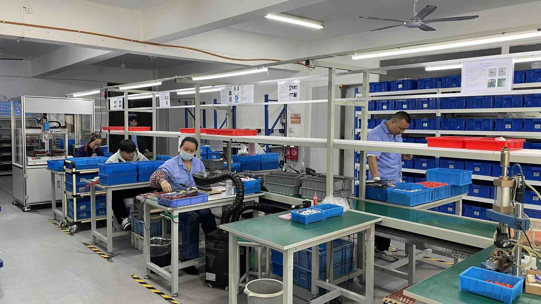
Frame stability is only one release condition. Final standing-desk compatibility also depends on the verified actuator, controller, supply, wiring, feedback, connector, and service interfaces. Production imagery provides context; the project-specific interface definition still governs.
Validate Before Production Release
Qualification should use the intended platform, top, accessories, wiring, controller, supply, and motion components. A practical plan can cover:
Supplier component testing is useful evidence, but it does not automatically qualify a different complete assembly.
What to Send for an Engineering Review
Send the frame layout, lifting-point count, mechanism drawing, moving mass, accessory loads, required travel, loaded speed, duty pattern, mounting and guidance, controller functions, power and connector requirements, environment, quantity, and required documents.
That gives the review one defined operating point instead of a list of unrelated maximum specifications.
Frequently Asked Questions
Use these questions to keep component selection connected to the complete standing-desk platform.
Can I select an actuator by force alone?
No. Load distribution, travel, loaded speed, duty, mounting, guidance, stability, power, and controller architecture also affect the selection.
How do two-, three-, and four-leg layouts change controller selection?
They change channel count and the coordination problem. ServoCylMotion locally documents YK-06, YK-08, and YK-10 as synchronized two-, three-, and four-channel models respectively. The actuator and wiring combination still requires project review.
Does a 29V actuator automatically work with a 29V controller and supply?
No. Current demand, startup behavior, connector pinout, polarity, control or feedback interface, cabling, and simultaneous motor operation must also be compatible.
Can the maximum force, fastest speed, and longest travel from one family be combined?
Not by default. Family figures can represent different configurations. Use one verified operating point for the required load, speed, travel, duty, and installation conditions.
What should be checked for platform stability?
Check the complete assembly across its travel. Structural stiffness, guidance, joints, feet, top stiffness, overhang, load placement, and mounting accuracy all contribute.
Can ServoCylMotion review components for an existing frame design?
Yes, when the interfaces are defined. Provide the drawing, lifting geometry, load, travel, loaded speed, duty, motor count, control behavior, power, and connector details so candidate components can be checked against the project.