

Custom Electric Cylinders for Non-Standard Motion
Engineer the cylinder around one real operating point: thrust, loaded speed, stroke, duty, mounting, feedback, environment, and machine envelope. Those constraints are resolved together before the configuration moves to drawing review.
Start with the motion the machine must complete.
Start with our electric cylinder family overview for the standard platform, or review our broader engineering capabilities when the project also involves controls, wiring, mounting, or system integration.
One operating point, reviewed as a system.
Force, speed, stroke, duty, installation geometry, control, feedback, and environment should be evaluated together. The configuration begins with the real loaded cycle—not a stack of independent maximum values.
Change the priority. See what the review must resolve.
Select the dominant project condition. The readout changes the first checks, likely trade-offs, and RFQ inputs without hiding the complete engineering scope.
Heavy load: review the complete force-versus-motion cycle.
Peak force alone does not define the actuator. Reversals, dwell, thermal duty, shock, alignment, gearbox, brake, and motor constraints can change the feasible configuration.
Long stroke: screen buckling, critical speed, sag, and support.
Unsupported length can reduce compression capacity quickly, while rotating screw speed can introduce whip or resonance before the motor reaches its own limit.
Tight envelope: resolve motor arrangement and interfaces together.
Inline, parallel/foldback, and geared arrangements redistribute axial and side space. Mounting, cable access, service clearance, and feedback hardware still need room.
Vertical axis: define power-off holding before release.
Efficient screw systems can backdrive when power is removed. The review must define a suitable brake or another validated load-holding method where gravity can move the load.
Harsh environment: specify dynamic exposure, not only a rating.
Dust, water jets, washdown, particles, chemicals, corrosion, temperature, and rod motion during exposure can require different wipers, bellows, seals, finishes, and lubrication.
All five priority reviews are shown when scripting is unavailable.
Configure the architecture around the operating point.
The main mechanical decisions are screw technology, motor arrangement, housing, rod interface, mounting geometry, sensors, and environmental protection.
Choose the drive by the job it must do.
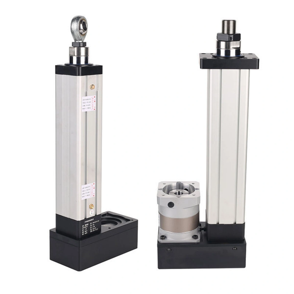
Ball screws are commonly selected when efficiency, positioning, and moderate-to-high speed are priorities. Planetary roller screws are better suited to compact high-force systems and repeated high-load cycles. Acme or lead screws can be useful where simplicity, lower speed, or non-backdriving behavior is more important than efficiency.
| Design area | Typical options | Main engineering trade-off |
|---|---|---|
| Screw drive | Ball screw, planetary roller screw, Acme/lead screw | Efficiency, force density, duty cycle, holding behavior, cost |
| Motor arrangement | Inline, parallel/foldback, geared | Axial length, side envelope, transmission complexity |
| Housing | Profile body, tie-rod or reinforced construction | Weight, rigidity, environmental robustness |
| Mounting | Flange, clevis, trunnion, foot, custom adapter | Load alignment, available space, frame compatibility |
| Feedback | Absolute encoder, incremental encoder, potentiometer, load sensing | Position retention, precision, control architecture |
| Protection | Wipers, bellows, sealing, protective finish | Dust, water, abrasive contamination, washdown exposure |
Heavy duty and long stroke create different release boundaries.
Review the full motion cycle, load path, unsupported length, speed, and guidance before choosing the mechanical architecture.
Heavy-Duty Electric Cylinder Engineering
A heavy duty electric cylinder must be sized from the complete force-versus-motion cycle rather than a peak-load number alone. Pressing, forming, insertion, lifting, and fluid-power replacement projects can impose short peak loads, long dwell periods, frequent reversals, shock loading, or high thermal duty.
Engineering review should therefore include:
- Continuous and peak push/pull force
- Loaded speed and acceleration
- Dwell time under load
- Cycles per hour and operating hours per day
- Vertical holding requirements
- Shock or impact conditions
- Gearbox, brake, and motor constraints
Long-Stroke Electric Cylinder Design
A long stroke electric cylinder introduces mechanical limits that become increasingly important as unsupported length increases.
Column buckling governs compressive loading. Euler’s relationship is commonly used as an early engineering screen:
Because allowable ideal buckling load varies inversely with the square of unsupported length, a longer extended condition can reduce compression capacity quickly. Push and pull loading should therefore be reviewed separately, and clevises, rod ends, adapters, and mounting compliance should be included in the effective unsupported length.
Critical screw speed is the second major limit. Long rotating screws can develop whip or resonance before the motor reaches its own speed limit. Screw root diameter, unsupported span, support arrangement, lead, target linear speed, and coupling alignment all affect the result.
Typical mitigation methods include a larger screw diameter, a higher lead to reduce screw RPM, intermediate support, improved bearing support, or a different axis architecture when stroke and speed requirements conflict.
For long horizontal extensions, structural sag and guide support should also be evaluated before finalizing the cylinder and machine frame.
Resolve the physical and control interfaces before brackets are released.
Front flange, rear clevis, trunnion, foot, and custom mounting interfaces can be adapted to different machine frames. ISO-style interfaces can also simplify replacement projects when the surrounding structure already follows a standardized cylinder layout.
The critical requirement is alignment through the full stroke. Radial loading can accelerate wear in rod bushings, seals, bearings, and screw components. When the driven mechanism cannot remain coaxial, use external linear guides and, where appropriate, self-aligning rod-end hardware to accommodate minor angular error.
Before releasing brackets or frames for machining, verify the current interface drawing through our CAD drawings and technical datasheets .
Mounting and alignment
Define the interface and maintain coaxial load transfer through the full stroke. Use external guidance for side force and overturning moment.
Motor, feedback and control
The mechanical cylinder should be selected together with the intended motor and control architecture.
Absolute encoders are useful when position retention through power cycles matters. Incremental encoders support precise velocity and position control but normally require a homing strategy. Potentiometer feedback can suit simpler positioning tasks.
Measured force
Where pressing or insertion force must be measured accurately, an in-line load sensor is preferable to estimating force only from motor current because friction and temperature can change the current-to-force relationship.
Coordinated axes
For machines using two or more coordinated axes, review mechanical layout, feedback, drive coordination, and fault handling together.
Multi-motor synchronization capability →Environmental protection
An enclosure rating should be treated as one part of the environmental specification, not a complete guarantee for every operating condition. Define dust, water jets, washdown, abrasive particles, chemicals, corrosion, temperature, and whether the rod moves during exposure.
Protection options
Depending on the application, protection can include rod wipers, scraper elements, bellows, corrosion-resistant hardware, protective coatings, and application-appropriate lubrication. Review dynamic sealing separately from static ingress tests for cycling in wet or contaminated environments.
Ten inputs move the project from idea to reviewable operating point.
Use the sizing and selection resource to organize the motion inputs before submitting the project.
| # | Input | What to provide |
|---|---|---|
| 1 | Working load | Continuous and peak force; push and/or pull |
| 2 | Loaded speed | Target speed at working load |
| 3 | Stroke | Total travel and usable travel |
| 4 | Duty cycle | Cycles/hour, dwell time, daily operating hours |
| 5 | Orientation | Horizontal, vertical, inclined, inverted |
| 6 | Mounting | Flange, clevis, trunnion, foot, custom geometry |
| 7 | Environment | Temperature, dust, moisture, washdown, chemicals |
| 8 | Control | Motor, drive, feedback, PLC/network preference |
| 9 | Documentation | CAD, wiring, force-speed data, test records |
| 10 | Project volume | Prototype quantity, annual demand, release timing |
Frequently Asked Questions
Use these answers to frame the requirement; final configuration feasibility depends on the supplied operating conditions.
What is a custom electric cylinder?
It is a rod-style electromechanical cylinder configured around a specific combination of force, stroke, loaded speed, duty cycle, mounting, feedback, and environmental requirements.
How should a custom cylinder be sized?
Define the required operating point first. Force, speed, stroke, duty, orientation, and environment should be evaluated together rather than selecting from independent maximum ratings.
When is a planetary roller screw appropriate?
It is generally considered when high force density, repeated high-load cycles, compact packaging, or demanding pressing duty justifies the added complexity and cost.
What limits a long-stroke design?
The main checks are compression buckling, critical screw speed, alignment, structural sag, thermal growth, and the ability of external guidance to control non-axial loads.
Can the rod carry side load?
The design should be treated as an axial-force device. Side forces and moments should be supported by separate guide components.
Which feedback options can be integrated?
Common choices include absolute encoders, incremental encoders, potentiometers, limit sensing, and load measurement. The final choice depends on the required control accuracy and system architecture.
Can a custom cylinder replace a hydraulic cylinder?
Potentially, but the conversion should be reviewed as a complete system, including real working force, speed, duty cycle, holding behavior, shock loads, controls, electrical supply, and environmental protection.
What should be included with an RFQ?
Provide working force, loaded speed, stroke, motion cycle, mounting orientation, installation envelope, environment, control preference, documentation needs, and estimated project volume.
Request an Engineering Review
Submit your application load, loaded speed, stroke, cycle profile, mounting arrangement, installation envelope, environmental conditions, control requirements, and project volume through our project RFQ page. ServoCylMotion can then review configuration feasibility against the supplied operating conditions.