

Custom Actuator Controllers, Panels and Interface Logic
Control-system OEM work is not only about changing a button cap or logo. A production-ready actuator interface connects the operator action, control logic, channel behavior, reset or homing expectations, wiring, connectors, mounting and packaging into one controlled configuration.
ServoCylMotion’s current product records support review of button-function programming, control logic, LED options, cable length, connector selection, mounting, branding or printing, color matching, private labeling and packaging. Wireless YK projects can also review pairing/frequency and motion-curve requirements. Exact availability depends on the chosen hardware and project.
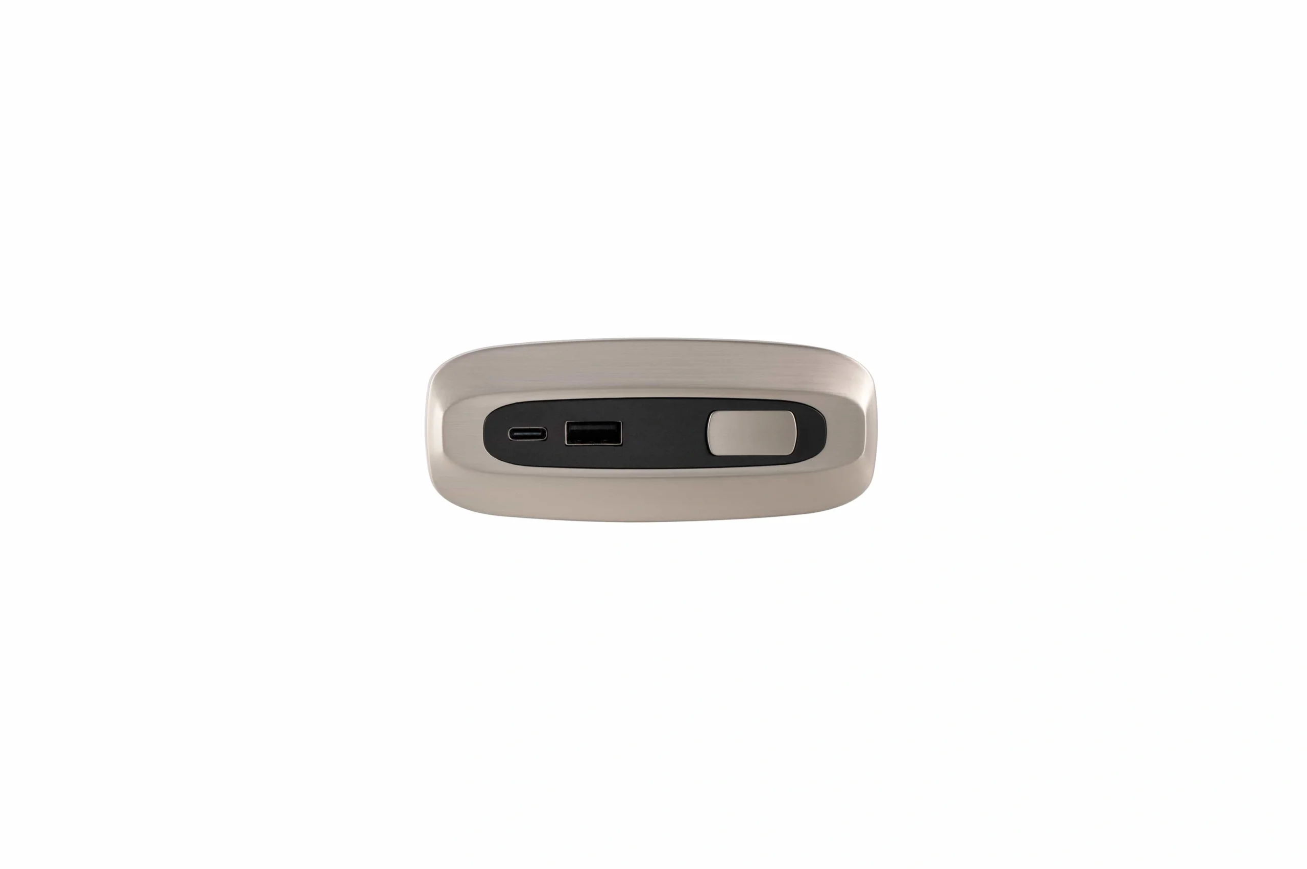
Operator panel configuration
Start with button map, panel form, charging need, connector, cable exit, mounting opening and branding requirements.
Customize the Interface Without Losing Control of the System
Separate visual/operator customization from electrical and motion behavior. A change that looks small on the front panel can alter connector, wiring, logic, power or validation requirements behind it.
Panel, buttons and branding
Review button-function programming, labels/icons, LED options, branding or printing, color matching and the physical panel or remote form.
Cables, connectors and mounting
Review cable length, connector selection, pinout, cable exit, mounting opening, panel thickness or receiver bracket needs as part of the actual equipment interface.
Channel behavior and wireless scope
Define control logic, channel relationship, reset/homing expectations and—where applicable—wireless pairing/frequency and motion-curve requirements.
Start From the User Interface, Then Resolve the Electrical Role
Select a control layer to expose the configuration questions that should be frozen before samples are approved.
Define the operator action before the electronics are frozen.
Specify button count, labels/icons, expected press behavior, any charging requirement, panel opening, cable exit, connector, branding and environmental/document needs.
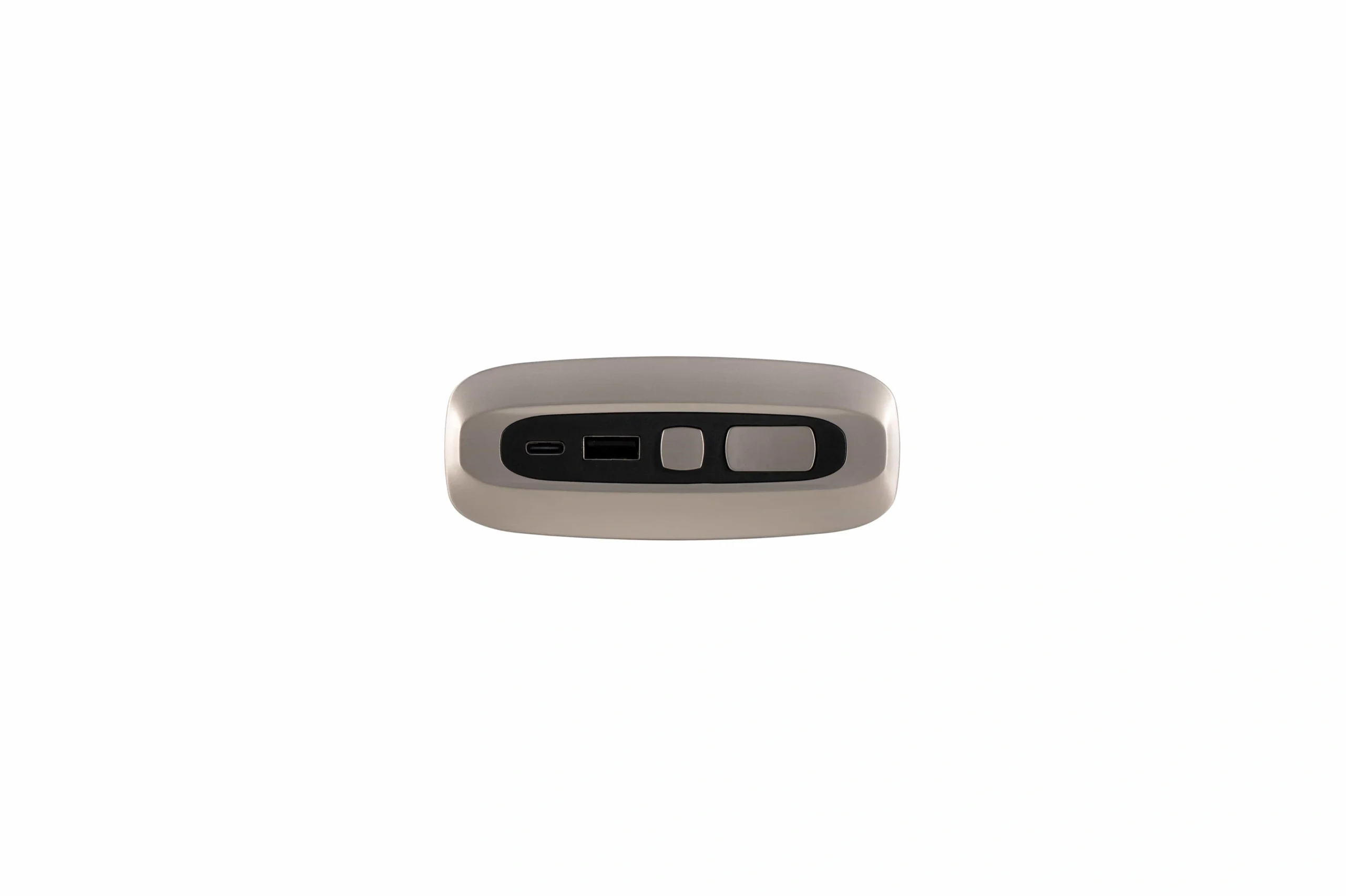
Move the Same Control Brief Through Five Gates
Keep operator intent, electrical behavior and production details aligned from first review through release.
Define operator actions
Button map, hold/toggle behavior, reset needs, channel relationships and any wireless actions.
Freeze physical and electrical boundaries
Panel opening, connector, pinout, cable length, cable exit, receiver position and available power.
Match the hardware family
Resolve HU/HS/HA panel or YK wireless route and identify which requested options are compatible.
Validate the real user flow
Check fit, button behavior, LED/charging behavior where applicable, wiring and interaction with the motion system.
Control the production details
Freeze approved logic, artwork/branding, connectors, cable lengths, packaging and other project-controlled details.
Use Product Pages to Resolve Hardware; Keep OEM Logic Here
The capability page owns custom control-system intent. Product pages own model-level selection and documented hardware differences.
Embedded control panels
Use the HU, HS and HA product family page to compare panel form, control ratio, charging interfaces and known model-specific cautions.
- Button count and operator form
- Charging requirement where documented
- Panel opening and mounting
- Connector / pinout / cable routing
Wireless motor controllers
Use the YK product family page to compare one-channel, standard two-channel and synchronized two-/three-/four-channel routes.
- Motor count and motion relationship
- Wireless pairing/frequency requirement
- Remote shell, buttons and icons
- Motion-curve review where applicable
Send the Inputs That Define the Interface
A useful control brief connects the human interface to the actual electrical and motion system.
Keep Appearance, Logic and Compatibility as Separate Proof Questions
A visually correct control panel is not automatically electrically compatible, and a connector that mates physically does not prove the signal logic is correct.
What the operator sees
Buttons, icons, LEDs, colors and branding should match the approved artwork and physical sample.
What the interface does
Control logic, channel relationship, reset, wireless pairing and any motion behavior must be checked against the intended sequence.
What the system accepts
Power, connectors, pinout, cable routing and connected motion hardware require configuration-level review before production release.
Control-System OEM FAQ
Use these answers to separate documented customization scope from model-specific approval.
What control-system elements can be customized?
Current local product data supports review of button-function programming, control logic, LED options, cable length, connector selection, mounting options, branding or printing, color matching, private labeling and packaging. YK wireless products additionally list remote-shell, button/icon, wireless pairing/frequency and motion-curve customization areas. Exact availability depends on the selected hardware and project.
Can I request a custom button map or operator panel?
Yes, button-function programming and branding/printing are documented review areas. Provide the complete button map, desired behavior, physical panel or remote constraints, connector and mounting information so the request can be checked against a suitable hardware route.
Does a 1-to-2 or 1-to-3 panel automatically synchronize actuators?
No. A control ratio or number of outputs does not by itself define the relationship between connected axes. State whether the motions are independent or coordinated and what reset/feedback behavior the equipment requires.
Can cable lengths and connectors be changed?
They are documented customization review areas. Confirm connector family, mating interface, pinout, cable length, cable exit and routing with the selected hardware before release.
Can wireless frequency or pairing behavior be customized?
The YK product record lists wireless frequency and pairing-protocol requirements among the reviewable customization scope. Confirm the target market, operating requirement and chosen controller model during engineering review.
What should be validated before production?
Validate the approved physical fit, operator actions, control sequence, LED or charging behavior where applicable, connector and cable fit, reset behavior, interaction with the selected actuator/controller system, and any project-specific acceptance criteria.
Freeze the user action, the electrical interface and the production details together.
Send the preferred panel/controller, motor count, button map, control sequence, reset needs, power, connector/pinout, cable length, mounting, branding, wireless requirements, packaging and approval criteria.