

Adjustable Bed Actuator Systems for OEM Bed Manufacturers
An actuator is only one part of a production-ready bed motion system. Define the motion zones first, then align actuators, controller logic, user interface, 29V power, frame geometry and cabling as one compatible assembly.
Start with the bed mechanism—not an actuator model number.
Document which sections move, how they are commanded, their angular travel, load distribution and the space available for motion hardware, controls, power and cabling.
Head and foot sections can use separate motor channels when the product requires distinct user commands.
Concurrent operation changes power demand and does not automatically mean the motors are position-synchronized.
When two motors must move together, define feedback, unequal-load response, reset and recovery logic.
Six interfaces have to agree before the bed is production-ready.
A matching connector or suitable force rating is not enough. Mechanical, electrical and control interfaces must be reviewed together.
Actuator or pair
Load path, stroke, installed length, loaded speed, duty and mounting condition.
Review linear actuators →Controller / receiver
Channel count, independent vs synchronized behavior, interface, reset and recovery logic.
Wireless motor controllers →Handset or panel
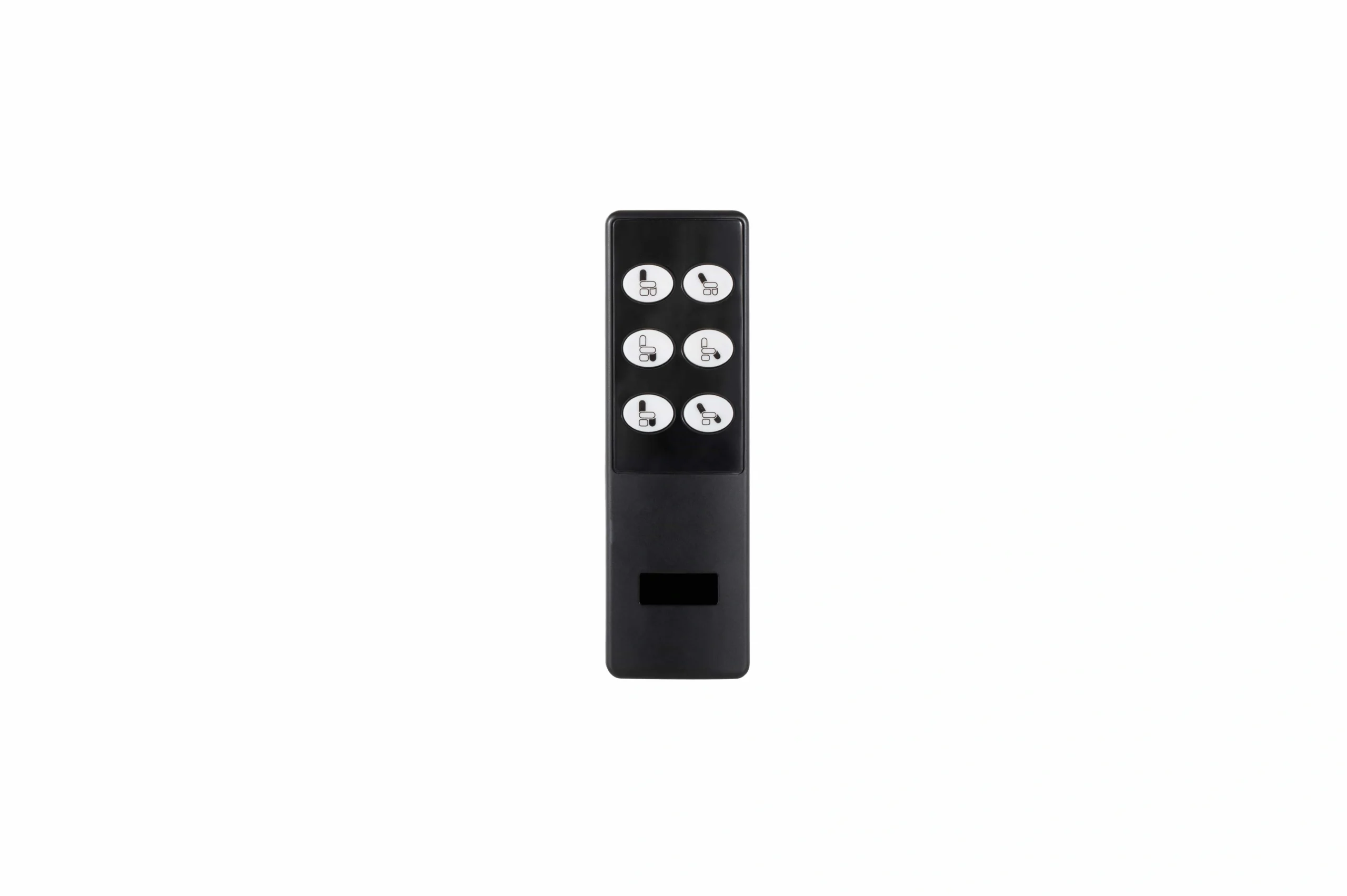
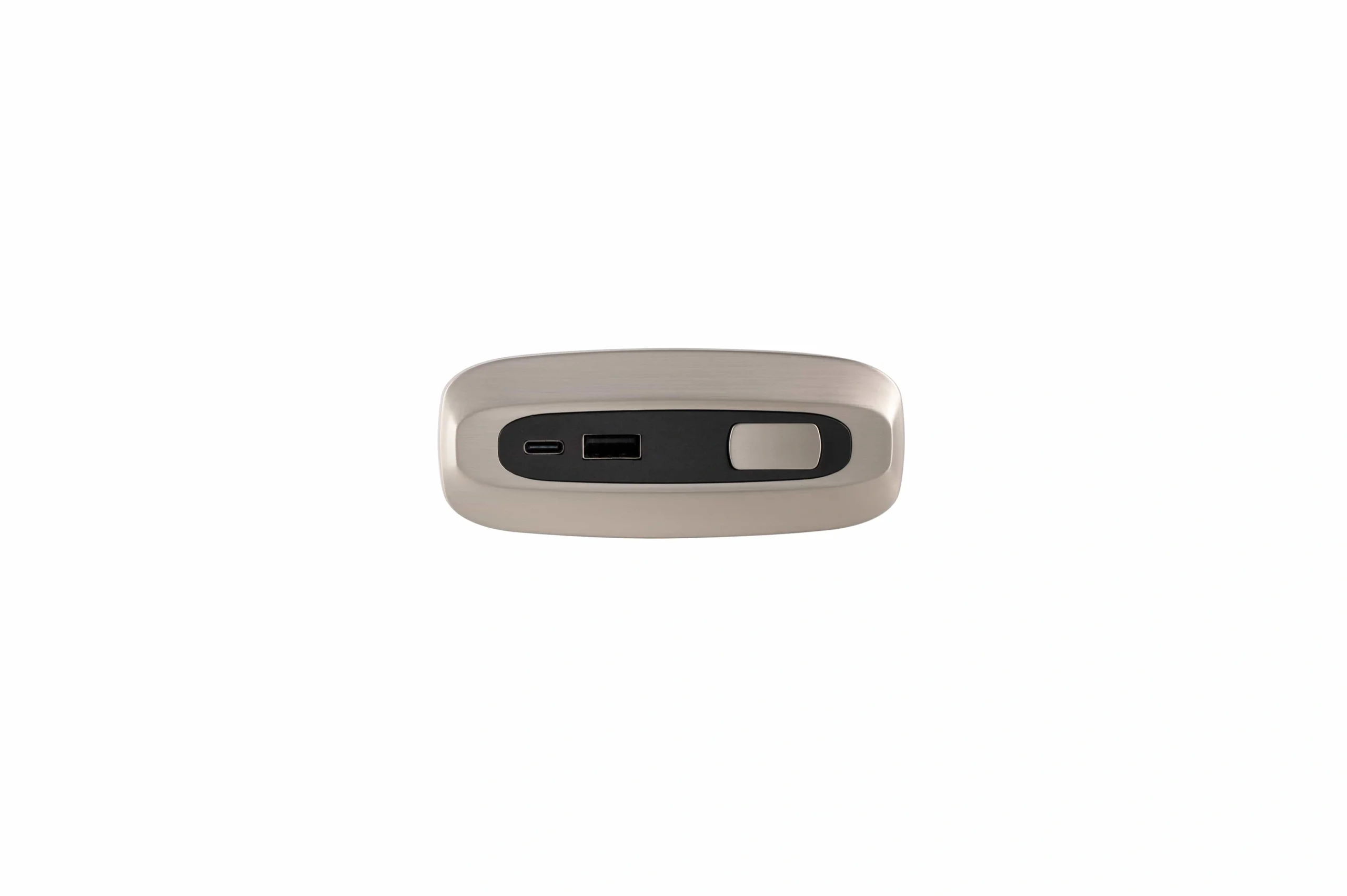
Button functions, wired/wireless interface, installation method and service access.
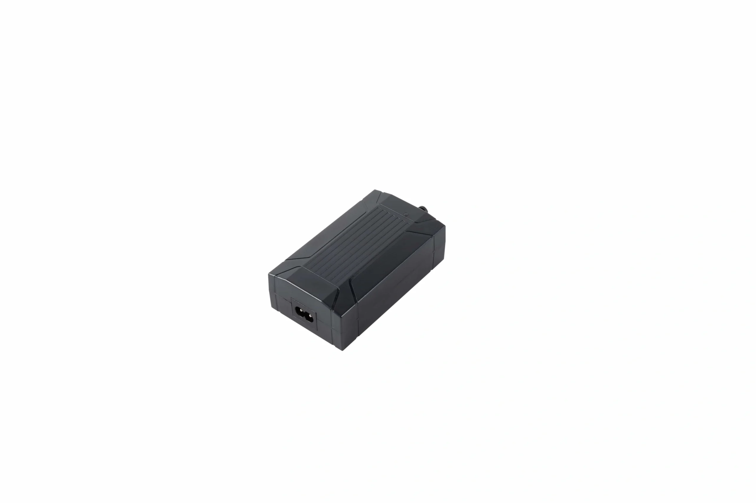
Embedded control panels →29V supply
Output requirement, destination AC input, plug, connector, cable length and operating demand.
29V power supplies →Cables + connectors
Pinout, polarity, cable routing, strain relief, bend path and replacement identification.
Frame interface
Pivots, brackets, crossbars, clearance, side-load control and service access.
The same nominal actuator can face a different load in a different bed frame.
Pivot location, lever arm, mattress and frame mass, friction and section angle all change the thrust requirement. Define the worst operating point rather than combining unrelated catalog maxima.
Two motors can mean two very different control architectures.
Use the architecture that matches the mechanism. Motor count alone does not tell you whether axes should move independently or stay coordinated.
Head and foot can be commanded separately.
YK-1 and YK-3 are documented in two-motor control contexts, with YK-3 specifically associated with dual-zone adjustable-bed use.
Freeze interface locations and cable paths before freezing the frame.
Handheld controllers, wireless remotes and embedded bed-side panels have different packaging and service implications. The power supply must then match the selected control/motor combination and destination market.
Use the actuator as a force element—not as a substitute guide.
The bed frame, pivots, brackets and crossbars should carry structural loads and keep unintended side loading out of the actuator. Review the complete motion in CAD or a controlled prototype.
Approve the BOM only after the full connection chain works under load.
A plug that fits is not evidence that voltage, polarity, pinout, feedback, protocol or motion logic are compatible.
| Review layer | Confirm before release | Evidence to retain |
|---|---|---|
| Mechanical | Mounting dimensions, stroke, force path, clearance and full loaded travel | Frame drawing, actuator drawing, fit review |
| Control | Channel count, independent/synchronized logic, reset and recovery behavior | Controller record, wiring logic, test sequence |
| Electrical | Voltage, current, polarity, connectors and feedback | Pinout, interface record, configuration ID |
| User interface | Handset/panel functions, pairing, mounting and service access | Button map, installation record |
| Power | Supply class, simultaneous demand, AC input, destination plug and cable | Power configuration and regional BOM |
| Production service | Cable routing, strain relief, replacement-part identification | Assembly drawing, wiring record, service BOM |
“Multifunctional bed” does not automatically mean powered adjustable-bed motion.
Consumer use of “multifunctional” can refer to storage, lighting, charging, speakers or furniture conversion. For an OEM motion project, define the powered function explicitly: which section moves, how it moves, how many actuators are required and how the user controls it.
Inputs that shorten the application review.
The more clearly the frame and motion zones are defined, the less likely the component selection is to drift away from the real mechanism.
What should I send for an adjustable bed actuator recommendation?
Send a drawing or CAD view, bed type, motion zones, load information, pivot/mounting geometry, stroke or angular travel, target movement time, duty/noise requirements, controller preferences, power market and documentation needs.
Can the head and foot sections move independently?
Yes, when the actuator and controller architecture is designed for independent motor channels. YK-1 and YK-3 records provide examples of two-motor control, with YK-3 documented for dual-zone adjustable-bed use.
When would synchronized dual-motor control be used?
When two motors must operate together for the required mechanism. Define the controlled axes, feedback method, reset behavior and unequal-load response before system approval.
Does a matching connector prove compatibility?
No. Verify voltage, current, polarity, pinout, feedback or protocol, controller model and commissioning behavior as well as the physical connector.
How do I choose between actuator options?
Start with the mechanism and operating point rather than a model name. Use the Product Selector to organize the requirement, then verify the candidate against the complete bed design.
What belongs in an adjustable-bed motion-system RFQ?
Include the frame drawing, required zones, motor count, load and geometry, stroke, speed, duty/noise target, control logic, destination power market, interface requirements, estimated volume and required CAD/wiring documentation.
Send the bed frame and motion requirements before locking the BOM.
Include motion zones, load and mounting geometry, stroke, target movement time, duty/noise target, control logic and destination-market power information.
Request a system recommendation →