

Linear Actuator System Compatibility: Controls, 29V Power, and Wiring
A compatible linear motion system is more than a set of parts with the same voltage label. The actuator, control device, power source, wiring, feedback, and application conditions all have to agree as one configuration.
Start from the exact actuator variant.
Voltage, loaded current, startup behavior, feedback, limits, and duty define the first compatibility boundary.
Match motor output and feedback behavior.
Channel count is only the start. Verify current limits, independent versus synchronized motion, feedback inputs, commands, and end-limit handling.
Check dynamic current, not label watts alone.
Startup, reversal, simultaneous motors, current-limit behavior, thermal conditions, and terminal voltage under load all matter.
Close the connector and conductor definition.
Confirm keying, pinout, polarity, contact rating, conductor size, installed length, voltage drop, signal reference, and flex routing.
For a preliminary compatibility review, follow this chain:
actuator requirements → control-device output and feedback → power-source capability → connector and wiring path → operating conditions
A shared 29V rating, a plug that physically mates, or the correct number of motor channels can be useful screening information. None of those facts proves compatibility by itself.
Move through compatibility in the same order the interfaces connect.
Select a step to expose the engineering decision that must be closed before release.
Do not advance while load current, feedback or limit behavior is still inferred.
Per-channel and combined limits must fit the real motor behavior.
Startup, reversal and simultaneous motion can expose a weak power path.
Mechanical mating does not replace controlled interface data.
Operate representative hardware and record unresolved conditions before release.
Quick Compatibility Check
Review this section against the exact configuration, revision, interfaces, and project conditions before release.
| System layer | Verify before approval | What is not enough |
|---|---|---|
| Actuator | Exact model and variant, operating voltage, loaded current, startup/stall behavior when available, motor architecture, feedback, limits, duty cycle | Product-family name or nominal voltage alone |
| Control device | Motor-output voltage, continuous/peak current limits, channel behavior, independent or synchronized motion, feedback inputs, end-limit handling, command interface | Port count or a generic “feedback supported” statement |
| Power source | Output voltage under load, dynamic current capacity, simultaneous motor demand, current-limit behavior, thermal conditions, AC input requirements | Nameplate watts calculated from voltage × current |
| Wiring and connectors | Connector family/keying, exact pinout, polarity, contact rating, conductor size, installed length, voltage drop, signal reference, routing and flex duty | A connector that fits or matching wire colors |
If one row is unknown, treat the configuration as not yet verified rather than assuming the remaining rows will compensate for it.
What 29V Tells You—and What It Does Not
Review this section against the exact configuration, revision, interfaces, and project conditions before release.
ServoCylMotion’s current project data includes 29V power-source classes at 1.8A, 2.0A, and 3.0A , corresponding to approximately 52.2W, 58W, and 87W by the basic relation (P = V \times I).
Those figures help compare available 29V power options . They do not tell you which source is correct for a specific actuator.
The next question is how the complete system behaves under its worst credible load case . A motor can demand substantially more current at startup, during a hard reversal, near stall, or when an obstruction prevents movement. If several motors can start together, the source and the control device must support the combined case. Cable and connector losses can also reduce the voltage that actually reaches the load.
For compatibility review, confirm:
- the allowed voltage range for the exact actuator and control device;
- loaded running current and any available startup, inrush, or stall data;
- how many motors can move at the same time;
- the current limit and recovery behavior of the power source and control device;
- voltage at the actuator under the highest expected load;
- duty cycle, ambient temperature, and enclosure conditions.
There is no single current-margin or cable-drop percentage that can safely replace model-specific data.
Check the Control Interface
Review this section against the exact configuration, revision, interfaces, and project conditions before release.
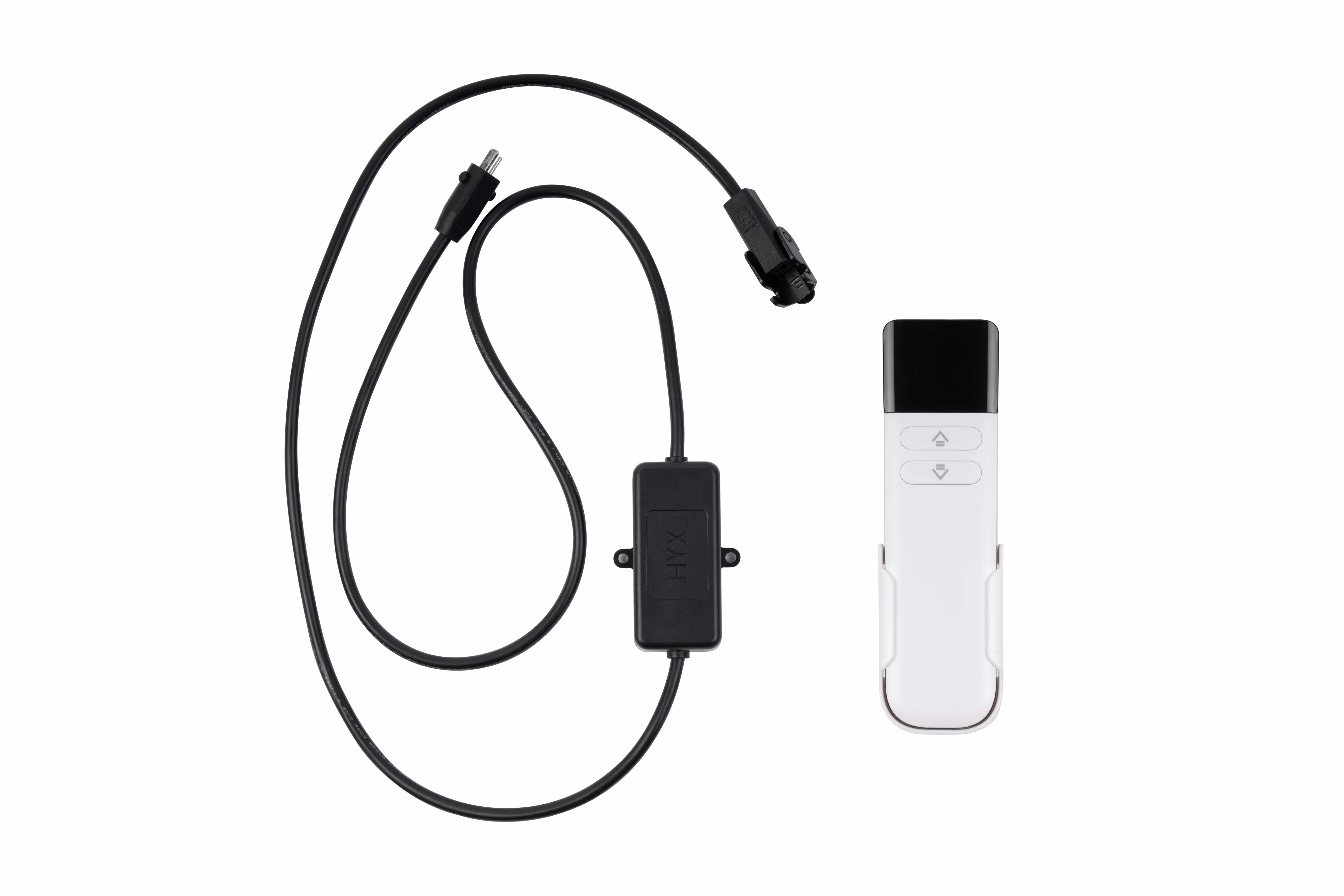
Control compatibility begins with the motor output, but it does not end there.
ServoCylMotion’s current YK-family project data covers one to four motor channels on a DC 29V family platform , with 60–120W documented at family level and synchronized variants in the range. That is useful family-level information, not a universal pairing matrix. Current controlled project evidence does not establish one feedback architecture, one sensor type, or one synchronization tolerance for every configuration.
When reviewing 29V multi-motor control options , check these items for the exact configuration:
Motor Output
The output voltage must fit the actuator’s allowed range, and the output stage must support real motor current—not only no-load current. For multi-channel equipment, verify both per-channel limits and the combined operating case.
Motion Mode
Clarify whether the motors need to:
- move independently;
- receive the same command at the same time; or
- remain position-aligned through closed-loop synchronization.
Those are different requirements. Parallel power does not automatically correct speed differences caused by load, tolerance, friction, or geometry. If aligned multi-motor motion is required, also review multi-motor synchronization .
Feedback and Position Signals
“Feedback” is not a single interface. Potentiometers, Hall sensors, optical encoders, discrete switches, analog outputs, pulse outputs, and digital communication can require different supply voltages, signal levels, inputs, calibration, and reference wiring.
Before pairing components, identify the exact feedback type and obtain its electrical specification.
Limits and Commands
Confirm whether end limits are internal or external, fixed or adjustable, and whether they interrupt motor power or only report a signal. If the application uses PLC, analog, PWM, serial, or bus commands, the electrical layer and protocol must match as well.
Check the Power Source Under Real Load
Review this section against the exact configuration, revision, interfaces, and project conditions before release.
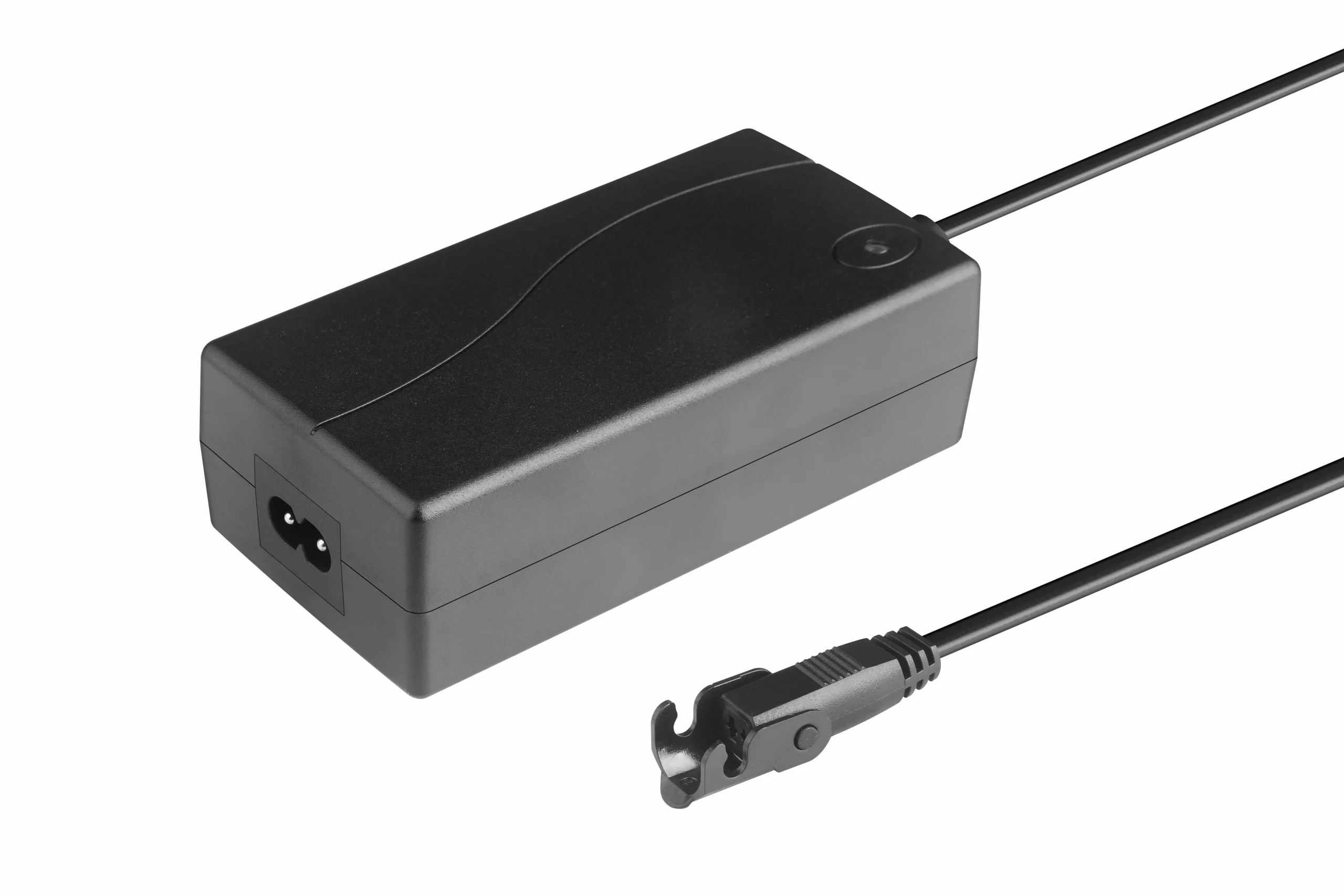
A simple power calculation is useful for comparing classes, but motor loads are dynamic.
A source that looks adequate from steady-state watts can still fail if it enters foldback, hiccup, or another protection mode during startup. Likewise, a higher source current rating does not fix an undersized output stage, connector, fuse, or cable.
Review the complete path:
AC input or battery → DC source → control device → motor channels → actuator
Key questions include:
- Does the source remain inside the required voltage window during startup and loaded motion?
- Can it support every motor that may start or reverse simultaneously?
- How does overcurrent protection behave when a motor starts hard or stalls?
- Are wiring, connectors, relays, and protection devices rated for the same current path?
- Does the enclosure provide enough thermal margin for the expected duty cycle?
- Are the AC input, regional plug, and installation requirements correct for the destination market?
Regional AC cordsets are a separate interface from low-voltage motor wiring. Use the power-cord options for mains-side selection, then verify the DC side independently.
Check Wiring Beyond Connector Fit
Review this section against the exact configuration, revision, interfaces, and project conditions before release.
Mechanical fit is only one part of an electrical interface.
Before power is applied, identify the complete connector and conductor definition:
- connector manufacturer/family, mating half, gender, keying, and pin-numbering view;
- motor-power pins and polarity;
- sensor supply, signal, and reference pins;
- limit or endstop conductors;
- contact current rating and approved conductor size;
- cable gauge and complete installed length;
- fixed versus repetitive-flex routing;
- shielding or signal-separation requirements when feedback or communication is present.
Wire count and color are inspection clues, not an interface specification. Extra conductors may carry feedback, sensor power, end-limit signals, or communication rather than motor current.
For project-specific harness changes, use the cable and interface customization capability only after the electrical functions and pinout are defined.
Cable Length and Voltage Drop
Calculate voltage drop over the full current path, including the outbound and return conductors and any material connector, relay, fuse, or terminal resistance. Then verify the actual terminal voltage under the expected load.
Longer cable can also matter on feedback and communication circuits. Signal routing, shielding, and flex requirements should follow the exact component documentation and the assembled-system EMC design rather than a universal rule.
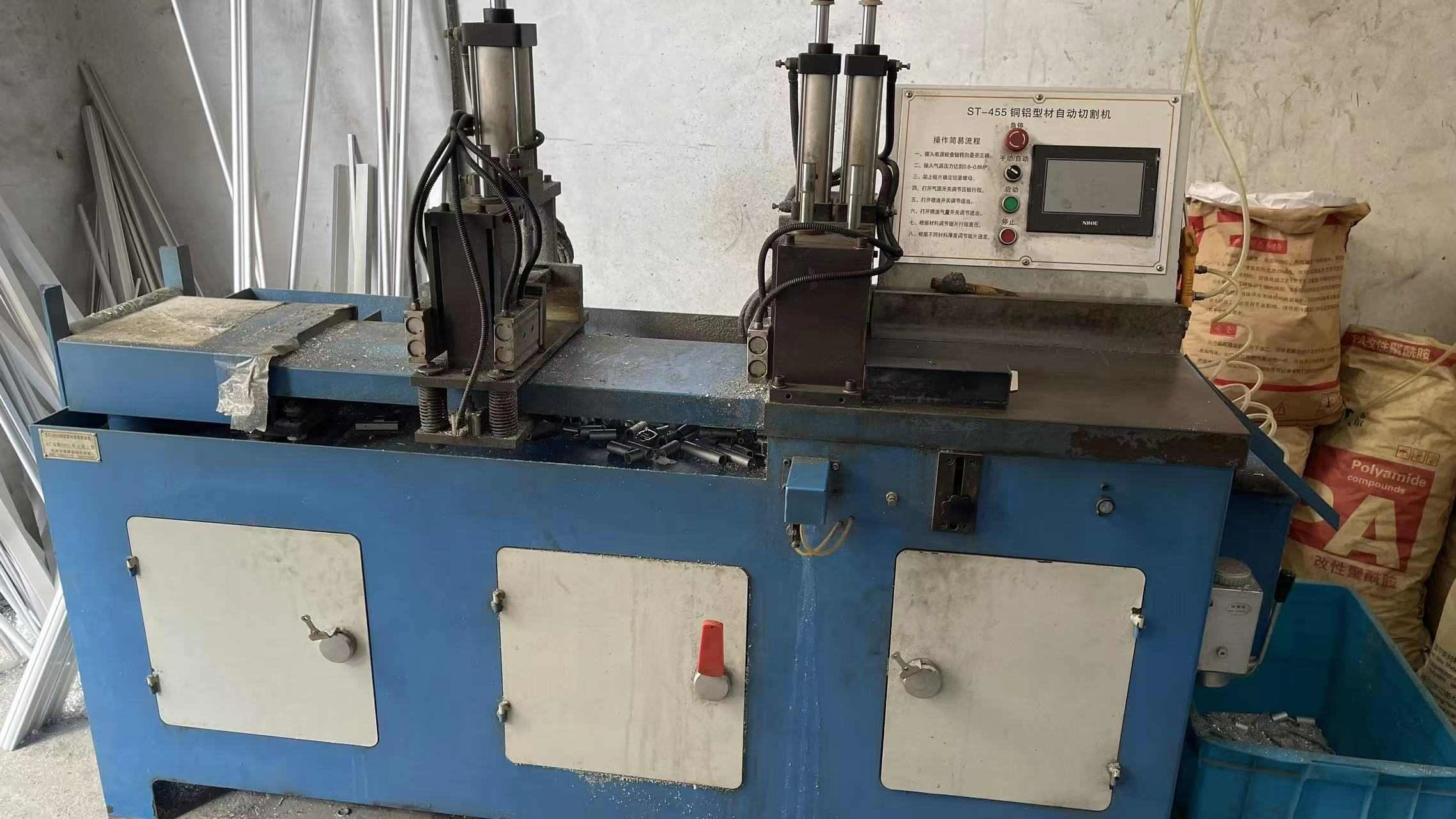
Compatibility decisions still need controlled electrical evidence.
First-party production context only. The image does not establish product-specific electrical ratings, pinout, test frequency, certification scope, or complete-system compatibility.
Evidence Required for an Exact Compatibility Review
Review this section against the exact configuration, revision, interfaces, and project conditions before release.
For an efficient engineering review, provide the exact configuration rather than only the application name.
| Required input | What to provide |
|---|---|
| Actuator | Exact model/variant, label photo, datasheet or drawing, voltage, load/current data, feedback option, limit information |
| Control device | Exact model, input/output ratings, channel count, intended motion mode, feedback inputs, command interface |
| Power source | Exact model or label, DC output rating, AC input, current-limit information when available |
| Connectors and wiring | Connector photos/drawings, pinout, polarity, wire count, gauge, cable length, branches or extensions |
| Multi-motor behavior | Number of motors, which motors move together, whether alignment/synchronization is required |
| Application | Load and motion description, duty pattern, ambient/enclosure conditions, destination market |
| Revision status | Drawing/manual revision or other identifier that proves the evidence matches the ordered hardware |
Use CAD and datasheet resources and technical documentation when available. If the exact interface is not documented, it should remain an open item rather than be inferred from a similar model.
Validate the Assembled Configuration Before Production
Review this section against the exact configuration, revision, interfaces, and project conditions before release.
A compatibility review should end with representative sample validation.
Depending on the application and available engineering procedures, verification may include:
- continuity and pin-identity checks before energizing the assembly;
- no-load direction and end-limit behavior;
- loaded extension and retraction;
- startup, reversal, and simultaneous-motor cases;
- actuator-terminal voltage during the highest-load motion;
- current peaks and any source or control-device reset;
- feedback scaling, counting, calibration, or homing behavior;
- cable routing and moving-cable checks where flexing is part of the installation;
- fault or obstruction behavior defined by the application’s risk assessment.
This is configuration validation, not final machine certification or safety approval.
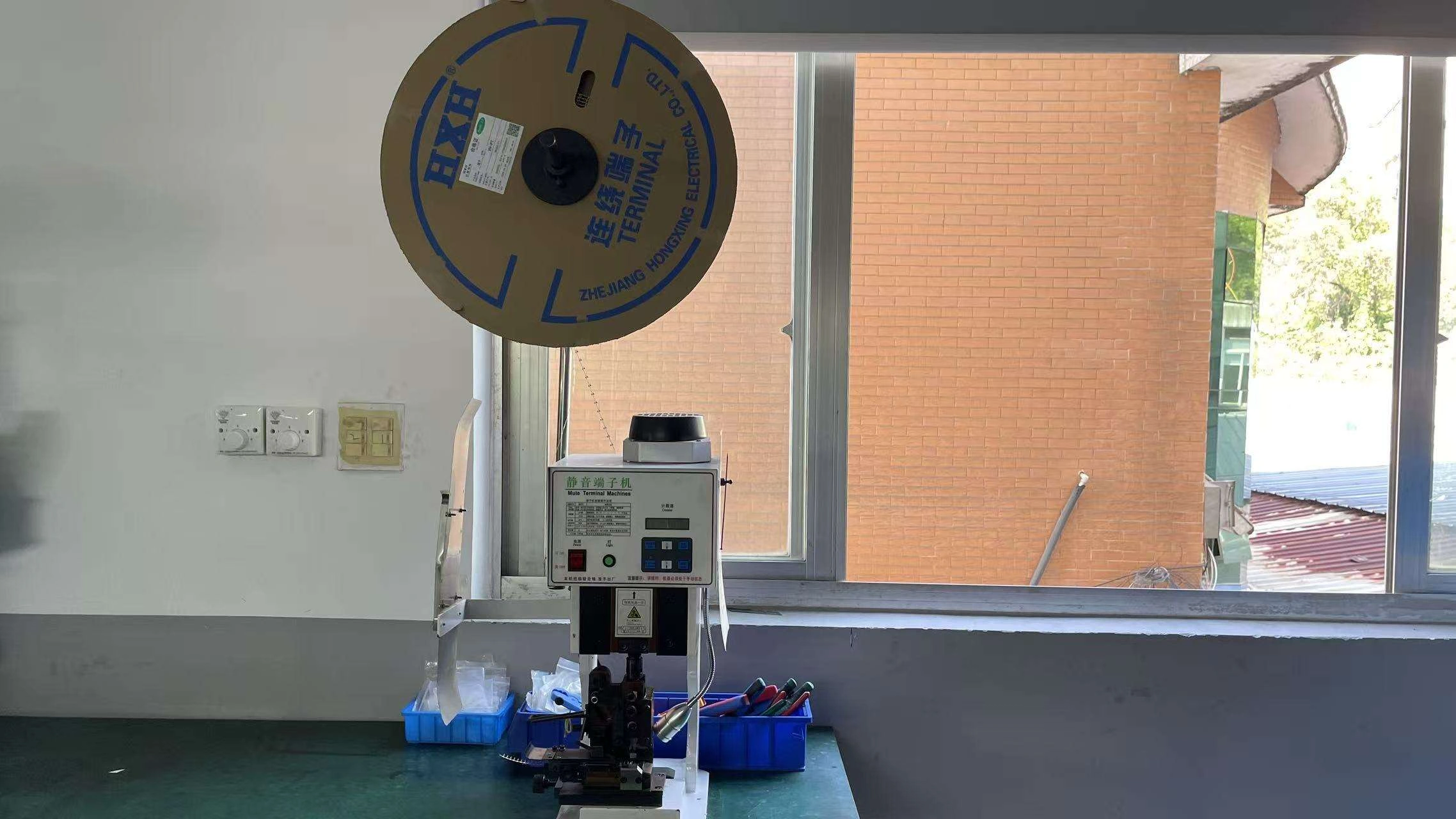
Keep wiring evidence tied to the exact assembly definition.
First-party production context only. The image does not establish a product-specific pinout, inspection frequency, certification scope, or complete-system compatibility.
Frequently Asked Questions
Review this section against the exact configuration, revision, interfaces, and project conditions before release.
Is the same nominal voltage enough to confirm compatibility?
No. Voltage must be correct, but current behavior, output limits, connector/pinout, feedback, wiring, and operating conditions also need to match.
Does a connector that fits prove the wiring is compatible?
No. Verify exact connector family and keying, pin numbering, pinout, polarity, contact rating, and signal functions from controlled documentation.
Which current value matters when checking a power source?
Use the exact actuator’s loaded operating data and, when available, startup/inrush and stall or obstruction behavior. Also account for every motor that can move simultaneously and the limits of the control device.
Can one 29V source run several actuators?
Potentially, but the answer depends on aggregate dynamic current, control-channel ratings, wiring, protection, duty cycle, and whether the motors move independently or together. The nominal voltage alone cannot answer it.
Does parallel motion mean the actuators are synchronized?
No. Sending the same command to multiple motors does not by itself correct position differences. Closed-loop synchronized motion requires a compatible feedback and control strategy.
Are feedback-equipped actuators interchangeable?
Not automatically. The feedback type, supply, output signal, reference wiring, resolution or pulse behavior, and calibration method all need to match the control input.
How much cable voltage drop is acceptable?
There is no universal percentage for every actuator system. Calculate the installed path and verify that the actual terminal voltage and performance remain inside the exact component limits.
What should I send for a compatibility review?
Send the exact actuator, control-device, and power-source models; electrical ratings; connector and pinout information; feedback type; motor count and motion requirement; cable lengths; and application conditions. Contact ServoCylMotion with the configuration package.
Get the Configuration Reviewed
Review this section against the exact configuration, revision, interfaces, and project conditions before release.
If you are combining a 29V actuator, control device, power source, or custom harness, send the complete interface package before locking the production BOM. ServoCylMotion can review the available documentation, identify unresolved compatibility points, and define what still needs sample validation.
You can also return to the engineering resources hub for related selection and documentation tools.
Close unresolved conditions before production release.
Send the exact configuration, drawings, interfaces, operating conditions and required evidence so the next engineering decision can be reviewed against real project inputs.