

Compact Electric Actuators for Tight Installation Envelopes
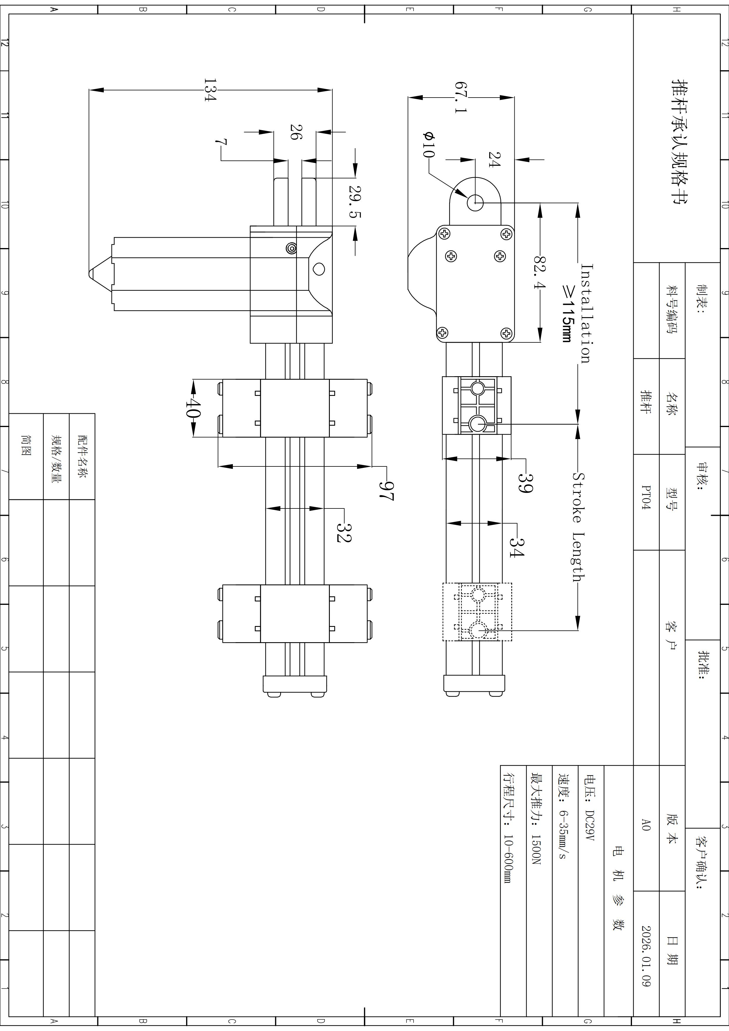
Use the PT Series when space is a primary constraint and thrust, travel, speed, mounting distance and packaging must be solved together. Published family limits span 1,500–6,000 N push, 6–50 mm/s and 10–1,000 mm stroke.
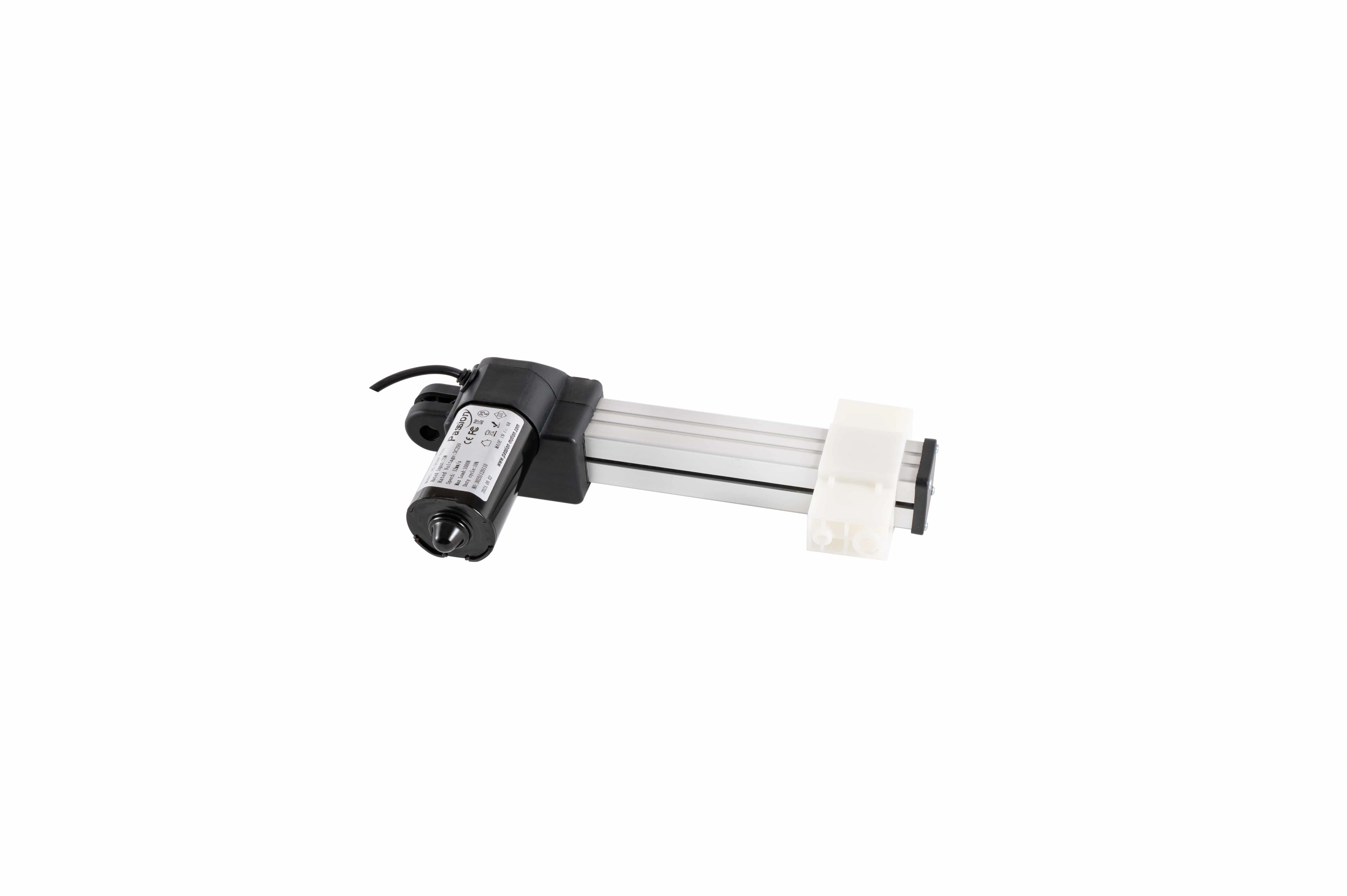
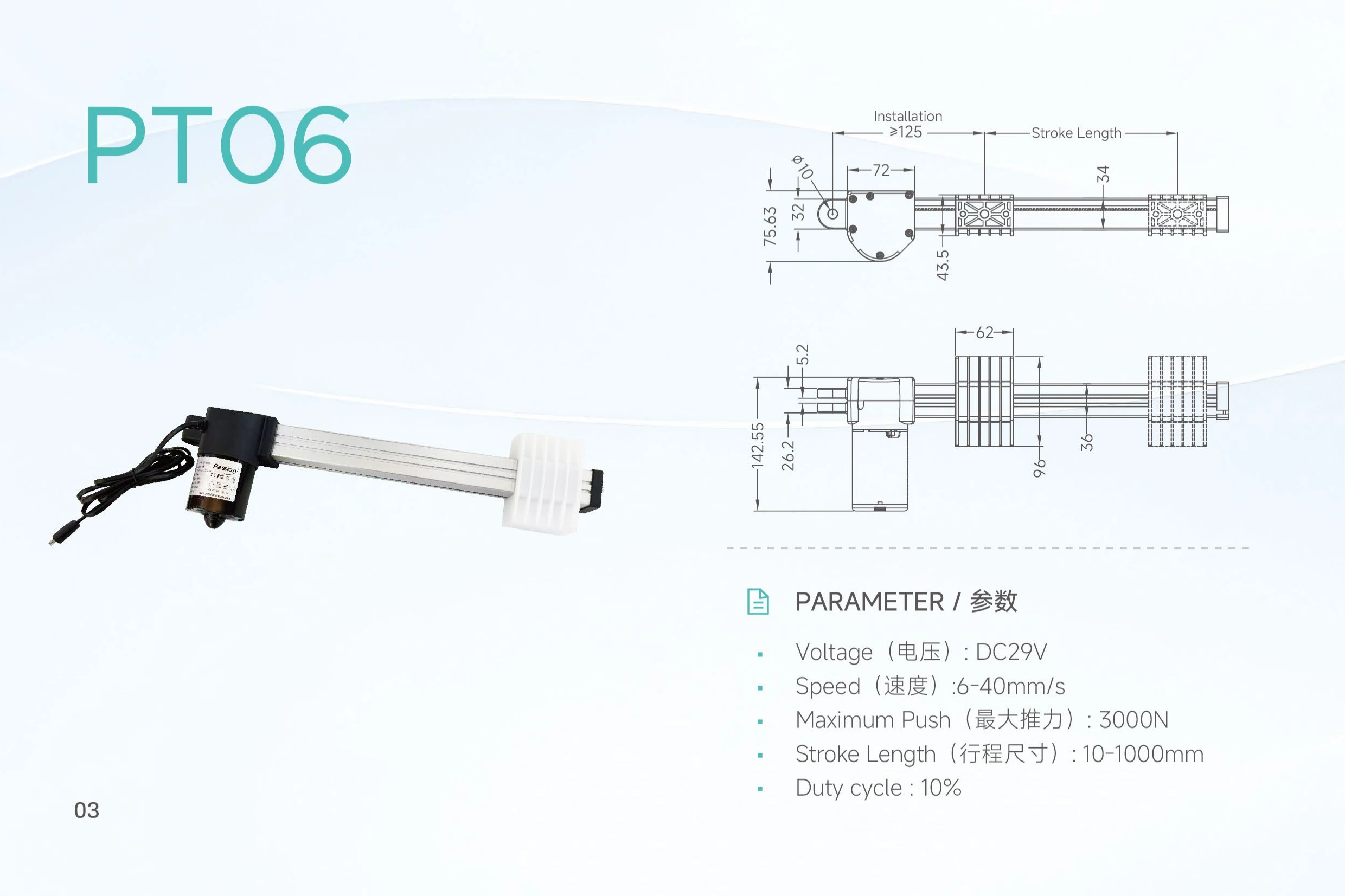
Treat the family data as a selection envelope—not one combined operating point.
The maximum force, fastest speed and longest stroke should remain separate requirements until a configuration-level combination is confirmed.
Start from the real moving load
Published maximum push spans 1,500–6,000 N across configurations. Size from the worst-case moving load and mechanism geometry rather than static payload alone.
Stroke is only the moving distance. The machine must clear the whole actuator.
Compact layouts shift the packaging problem into body width, bracket geometry, cable exit, carriage travel and service access. Confirm the complete installed envelope before freezing surrounding structure.
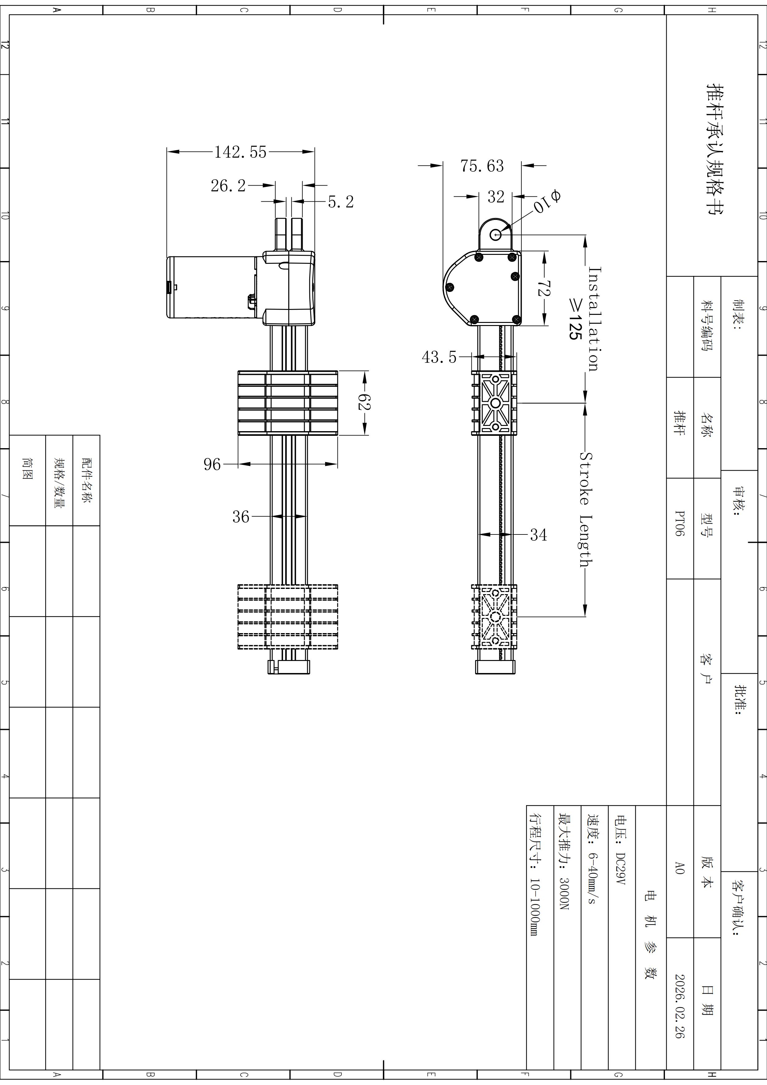 VERIFY FULL MOTION CLEARANCE
Force, loaded speed and duty belong in the same engineering conversation.
Define the motion path, working load and target travel time together. Published speed without load conditions should not be treated as guaranteed loaded speed.
Mechanical selection and electrical architecture should converge before release.
The PT family is documented locally as 29V. Power, switching, feedback and multi-motor behavior still require configuration-level review.
29V power options
Review supply capacity, connectors, startup behavior and the complete motion-system demand.
Review power supplies →Embedded control panels
Keep simple reversing, position control and system interfaces separate from the mechanical model choice.
Review control panels →Wireless motor controllers
State motor count, synchronization need and control behavior before selecting a controller architecture.
Review controllers →Inspect the production environment as context, then verify the engineering evidence separately.
The PT family page includes first-party factory imagery because buyers evaluating a compact-motion platform also need manufacturing context. The image is intentionally not used to claim a PT-model-specific process, tolerance capability or certification.
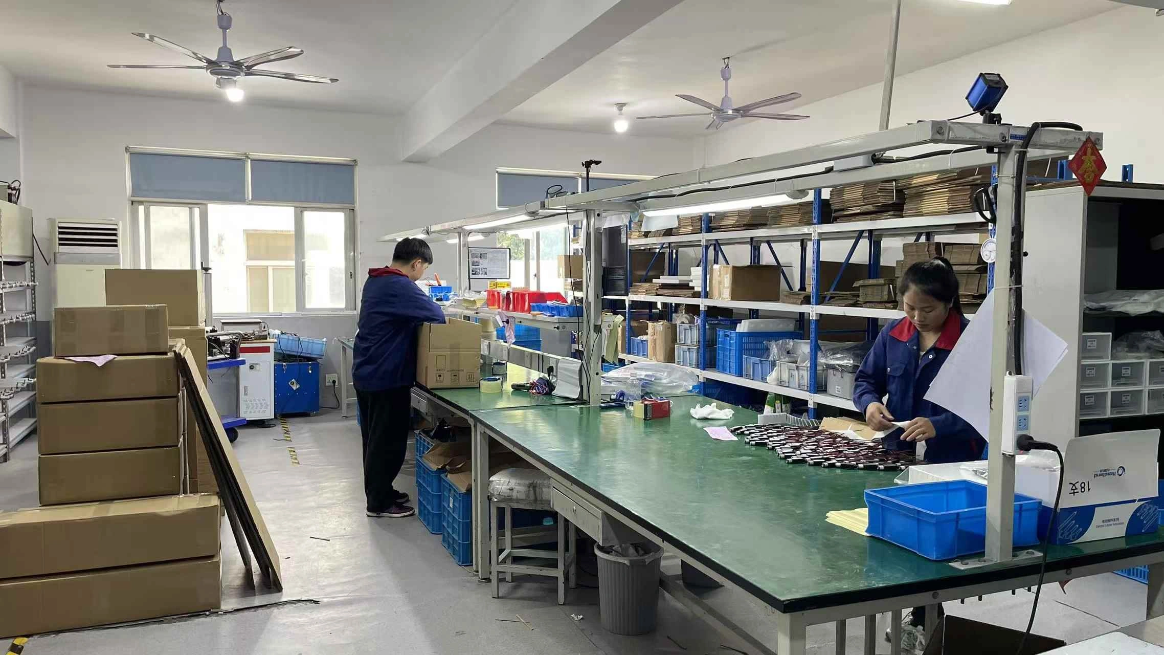 Assembly environment / first-party factory image
Send the operating point and the installation limits together.
A useful RFQ includes load direction, working load, loaded speed, usable stroke, retracted space, bracket points, cycle, environment, control behavior, power architecture, quantity and required documents.
Questions that prevent an envelope-only selection.
Use the family page to narrow the problem, then request model/configuration confirmation before release.
What does “compact” mean for the PT Series?
It describes a family intended for space-constrained mechanisms. There is no single industry dimension that defines compactness; verify the complete installed envelope including brackets, motor housing and cable clearance.
Can the actuator be selected from maximum push force alone?
No. Working load, loaded speed, stroke, installation geometry, duty cycle and environment should be reviewed together.
Are the fastest speed and highest force available together?
Do not assume so. The local data publishes family ranges, not a configuration-level force-speed matrix.
How should stroke be specified?
Specify usable mechanism travel, then verify retracted and extended dimensions and clearance throughout the full motion path.
Can the actuator carry side load?
Design the mechanism so guides, slides, hinges or bearings carry lateral loads. Use the actuator primarily for axial motion unless a released configuration explicitly states otherwise.
Does feedback automatically provide positioning control?
No. Feedback hardware, controller compatibility, logic, homing and wiring must work together.
What should be sent for quotation?
Send load direction, working load, required loaded speed, stroke, installation-space limits, cycle, environment, control behavior, quantity and required documents. A drawing or mechanism sketch is especially useful.
Start with the mechanism envelope. Finish with a verified operating point.
Provide load, loaded speed, stroke, installation space, duty, environment, controls, quantity and documentation requirements.
Request engineering review →