

29V Linear Actuators for Direct-Push Motion
ServoCylMotion’s ZT series includes seven DC 29V linear actuator models for straight-line push applications.
Compare the family before opening a model.
Use the model rail to compare published envelopes. Final selection still depends on the real operating point.
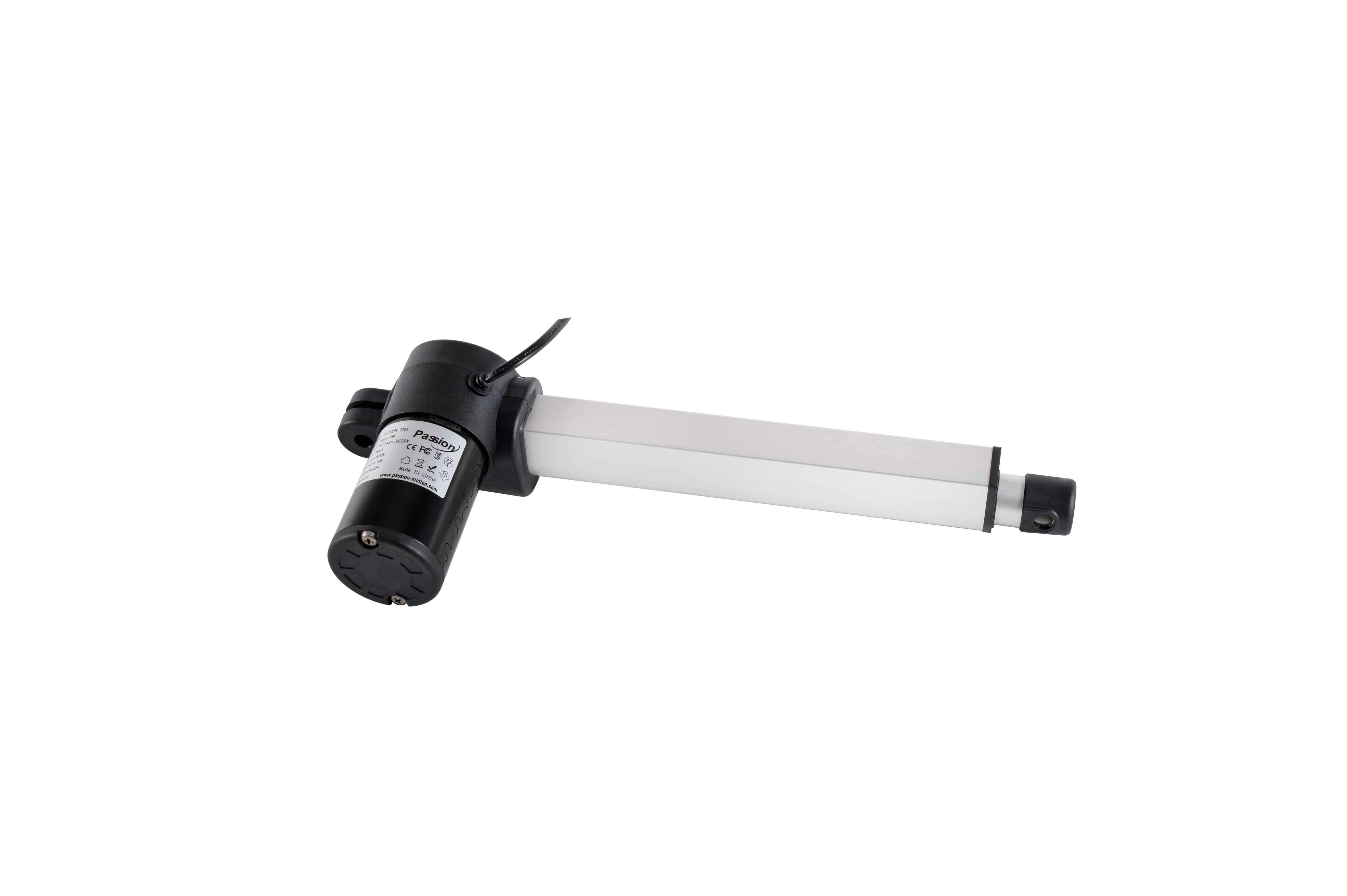
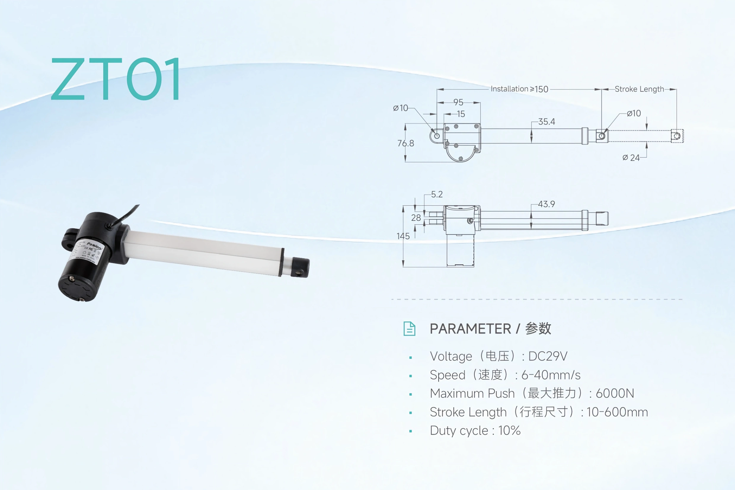
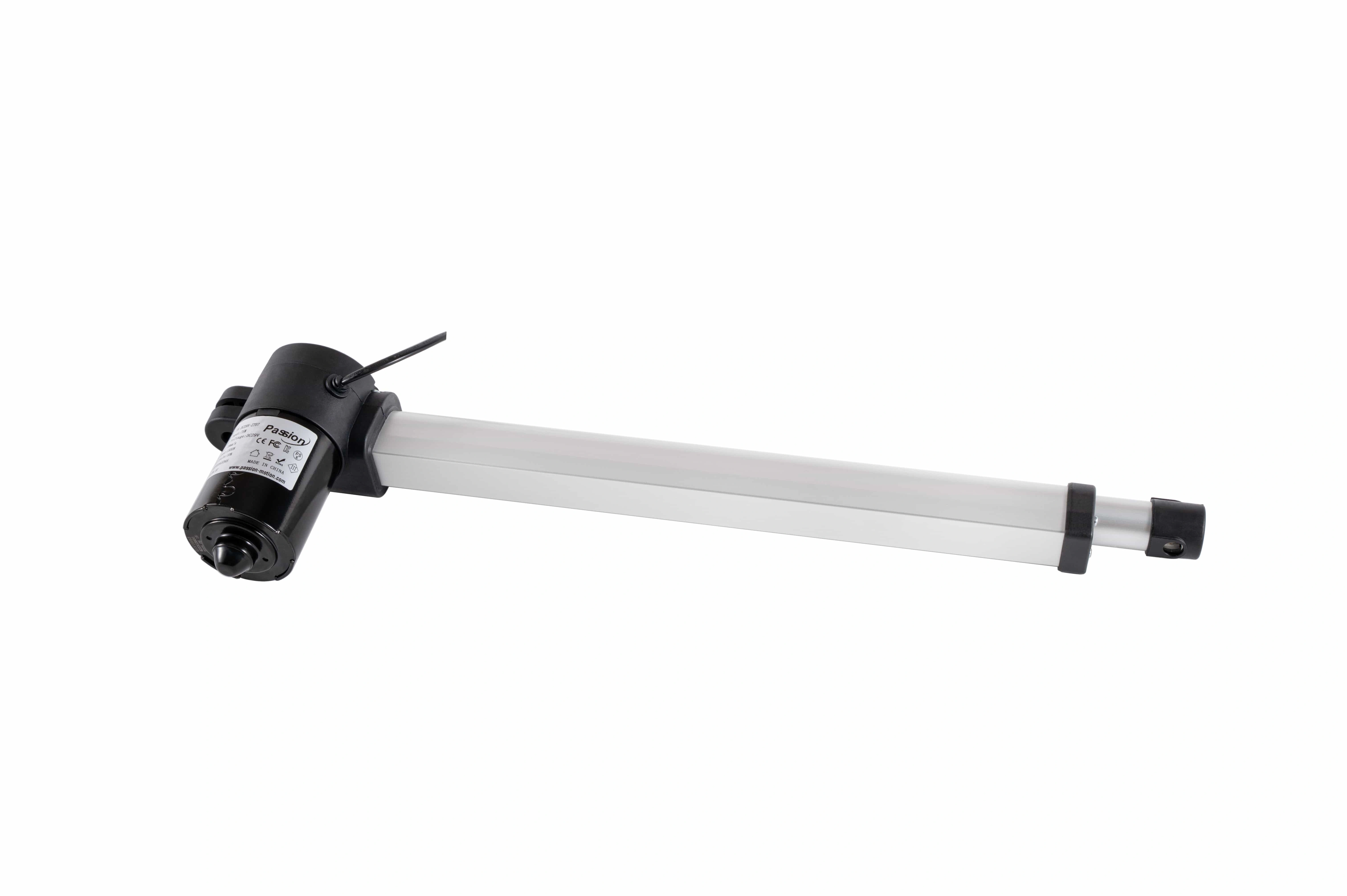
ZT01
- MAX PUSH
- 6,000 N
- SPEED
- 6–40 mm/s
- STROKE
- 10–600 mm
- INSTALL REF.
- ≥150 mm
The bars compare published maximum fields independently; they do not imply a combined operating point.
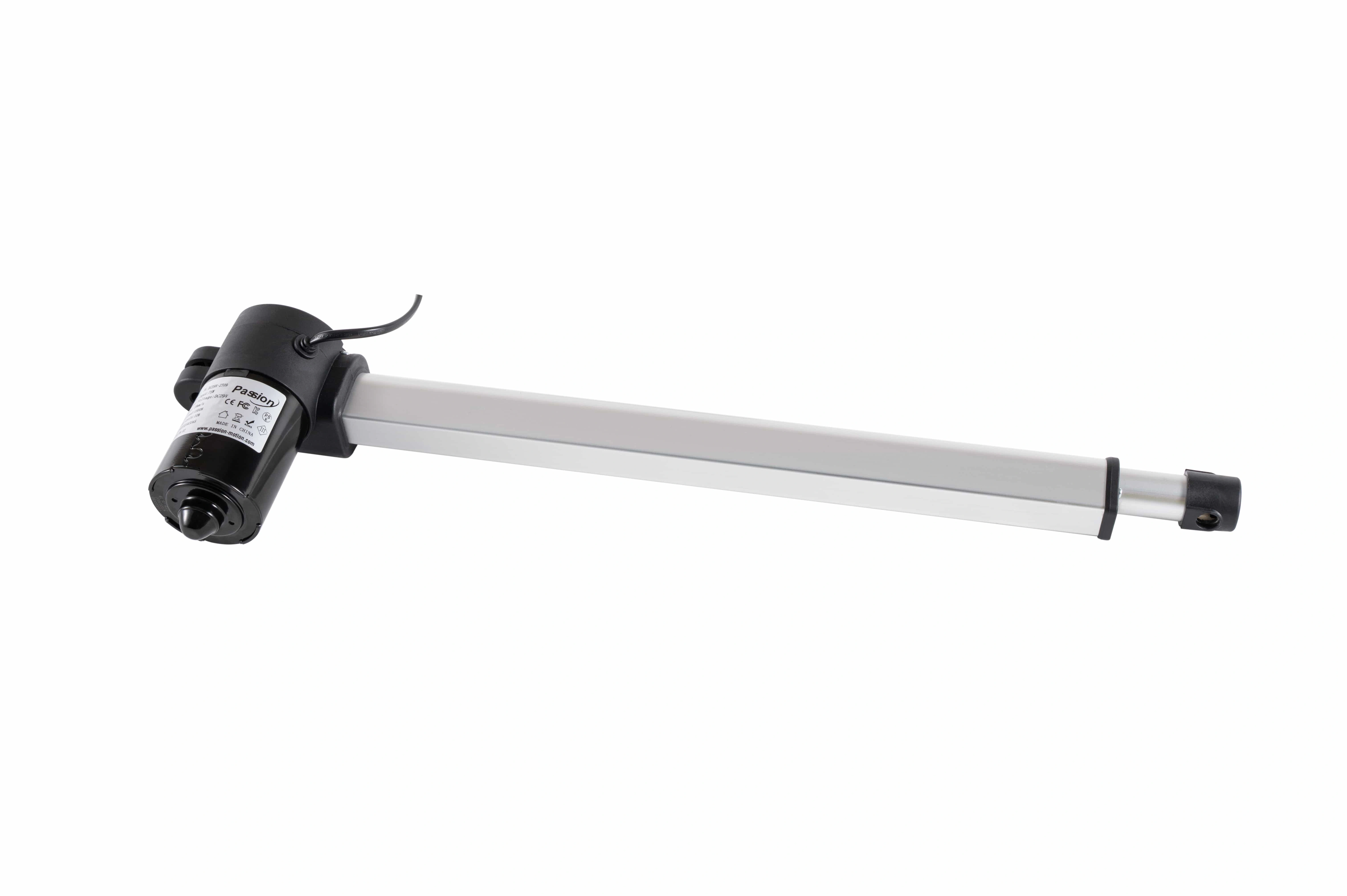
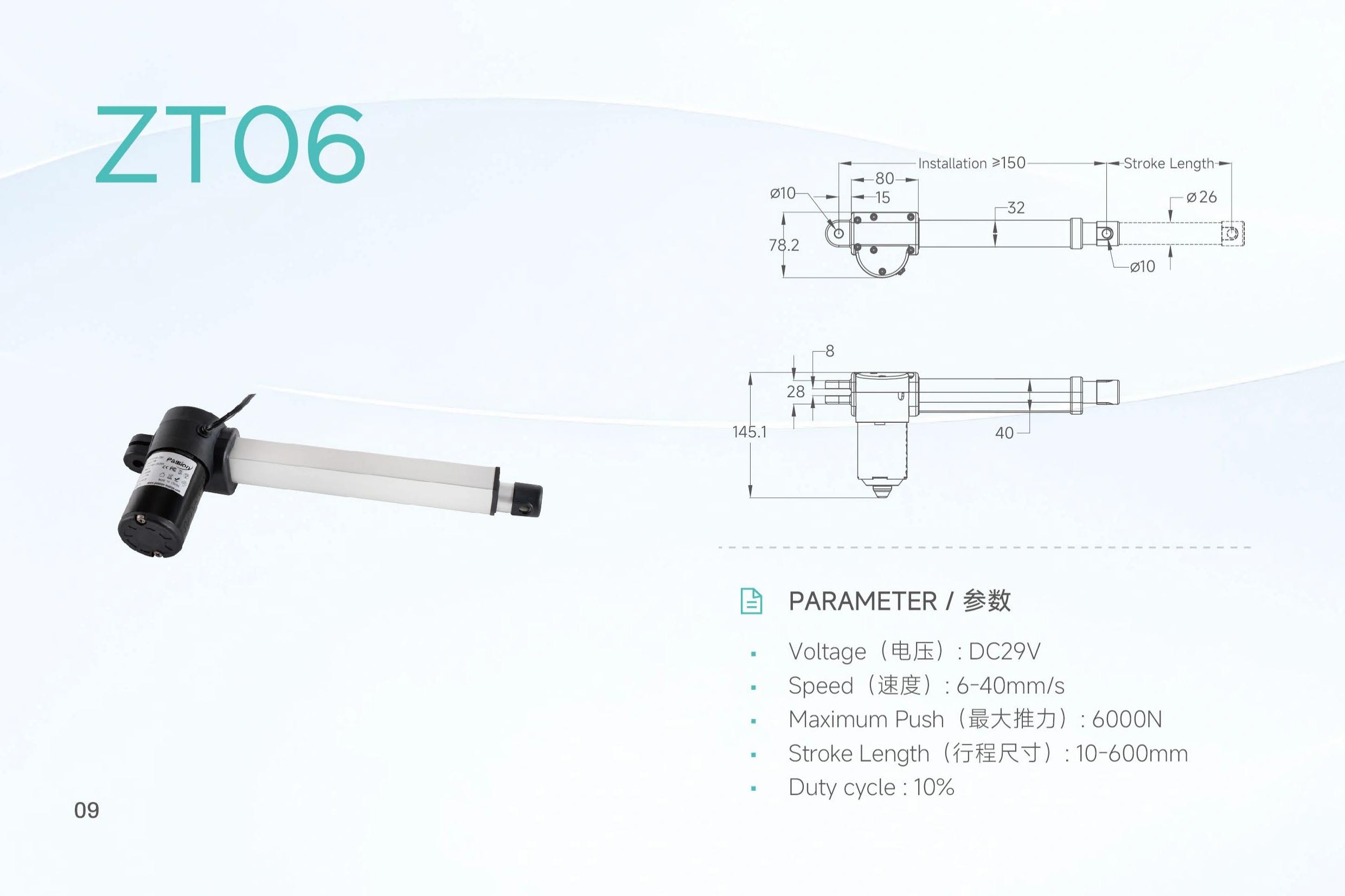
ZT06
- MAX PUSH
- 6,000 N
- SPEED
- 6–40 mm/s
- STROKE
- 10–600 mm
- INSTALL REF.
- ≥150 mm
The bars compare published maximum fields independently; they do not imply a combined operating point.
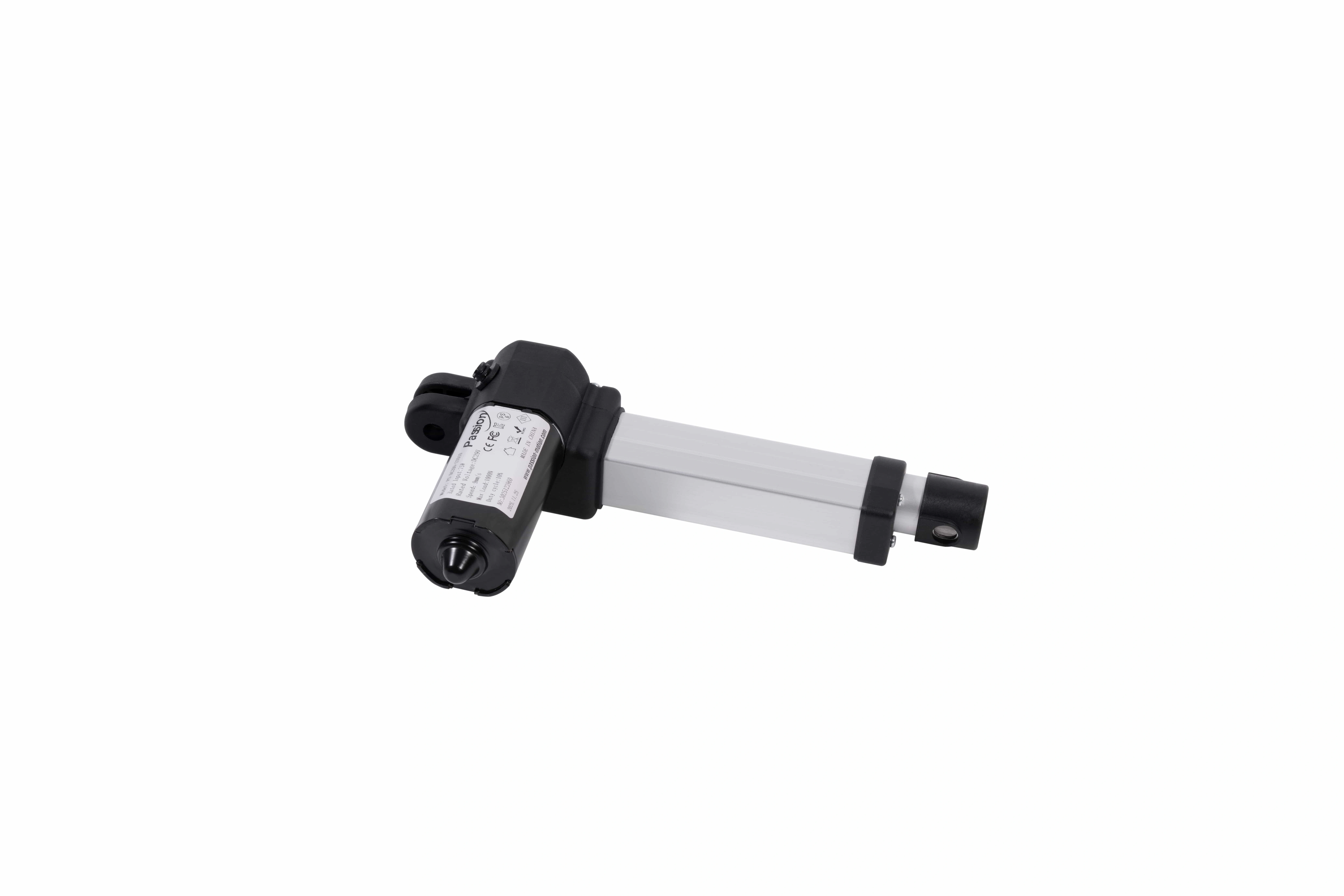
ZT09
- MAX PUSH
- 3,000 N
- SPEED
- 6–40 mm/s
- STROKE
- 10–600 mm
- INSTALL REF.
- ≥140 mm
The bars compare published maximum fields independently; they do not imply a combined operating point.
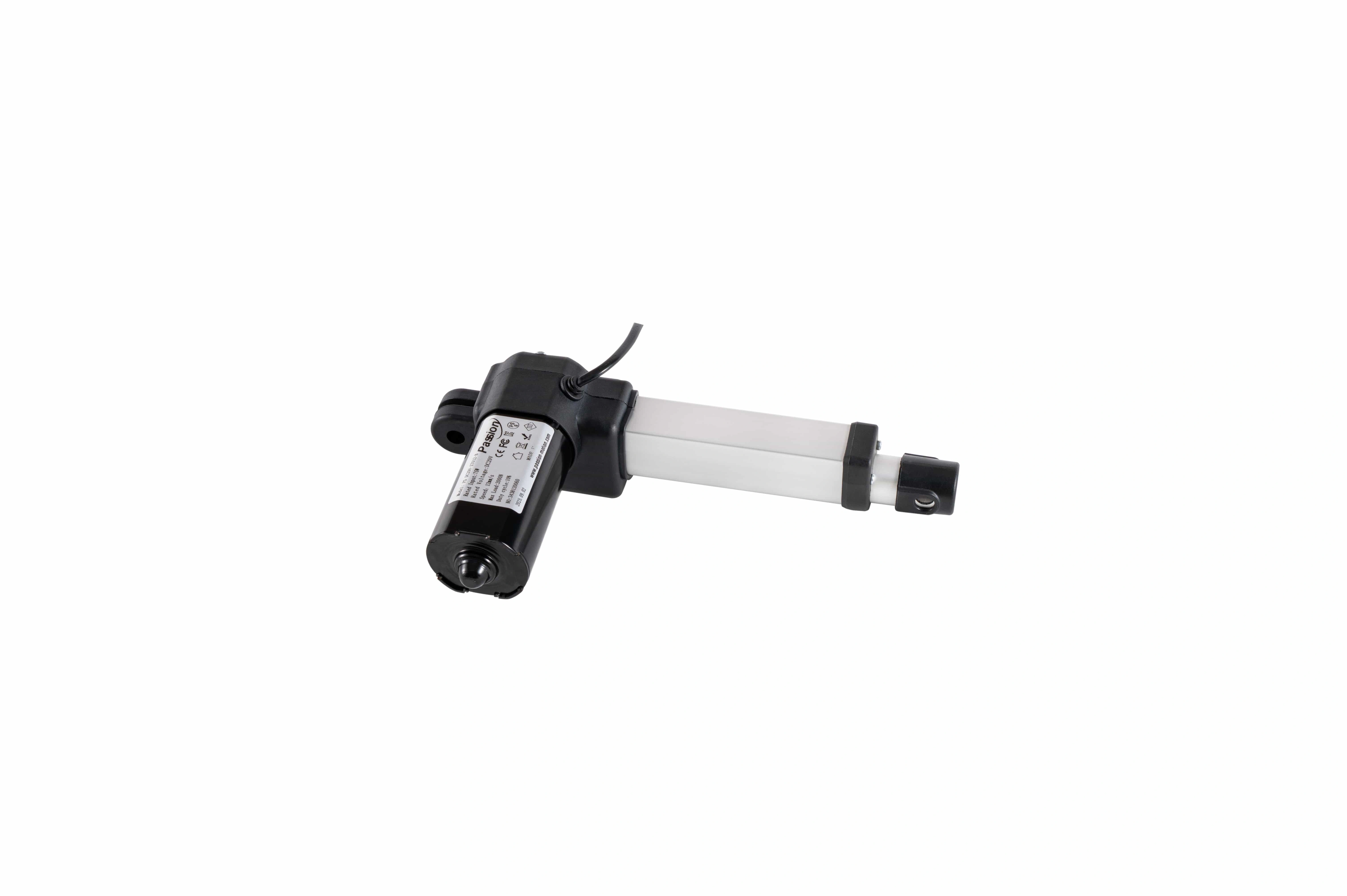
ZT11
- MAX PUSH
- 2,000 N
- SPEED
- 5–30 mm/s
- STROKE
- 10–500 mm
- INSTALL REF.
- ≥130 mm
The bars compare published maximum fields independently; they do not imply a combined operating point.
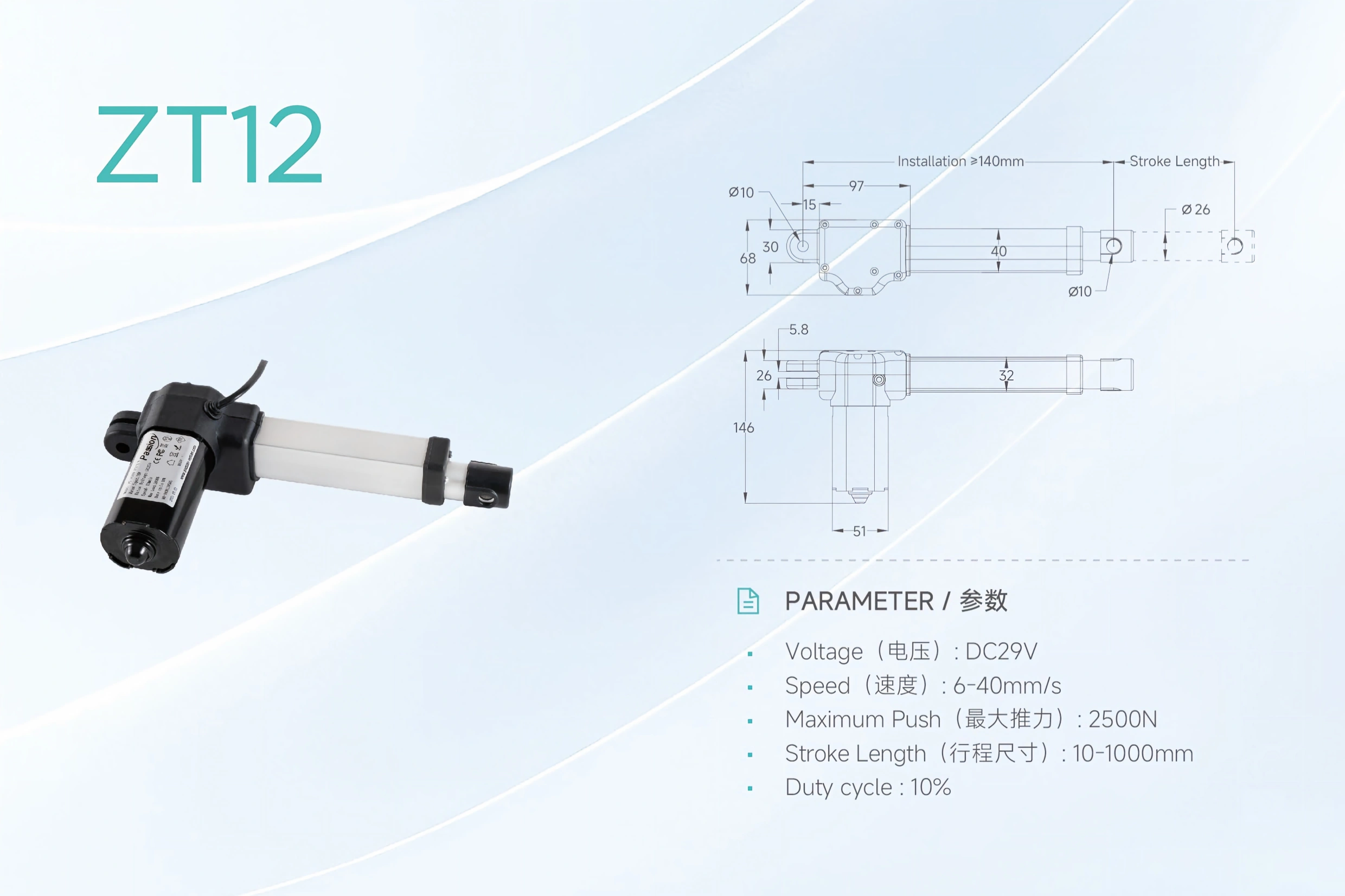
ZT12
- MAX PUSH
- 2,500 N
- SPEED
- 6–40 mm/s
- STROKE
- 10–1,000 mm
- INSTALL REF.
- ≥140 mm
The bars compare published maximum fields independently; they do not imply a combined operating point.
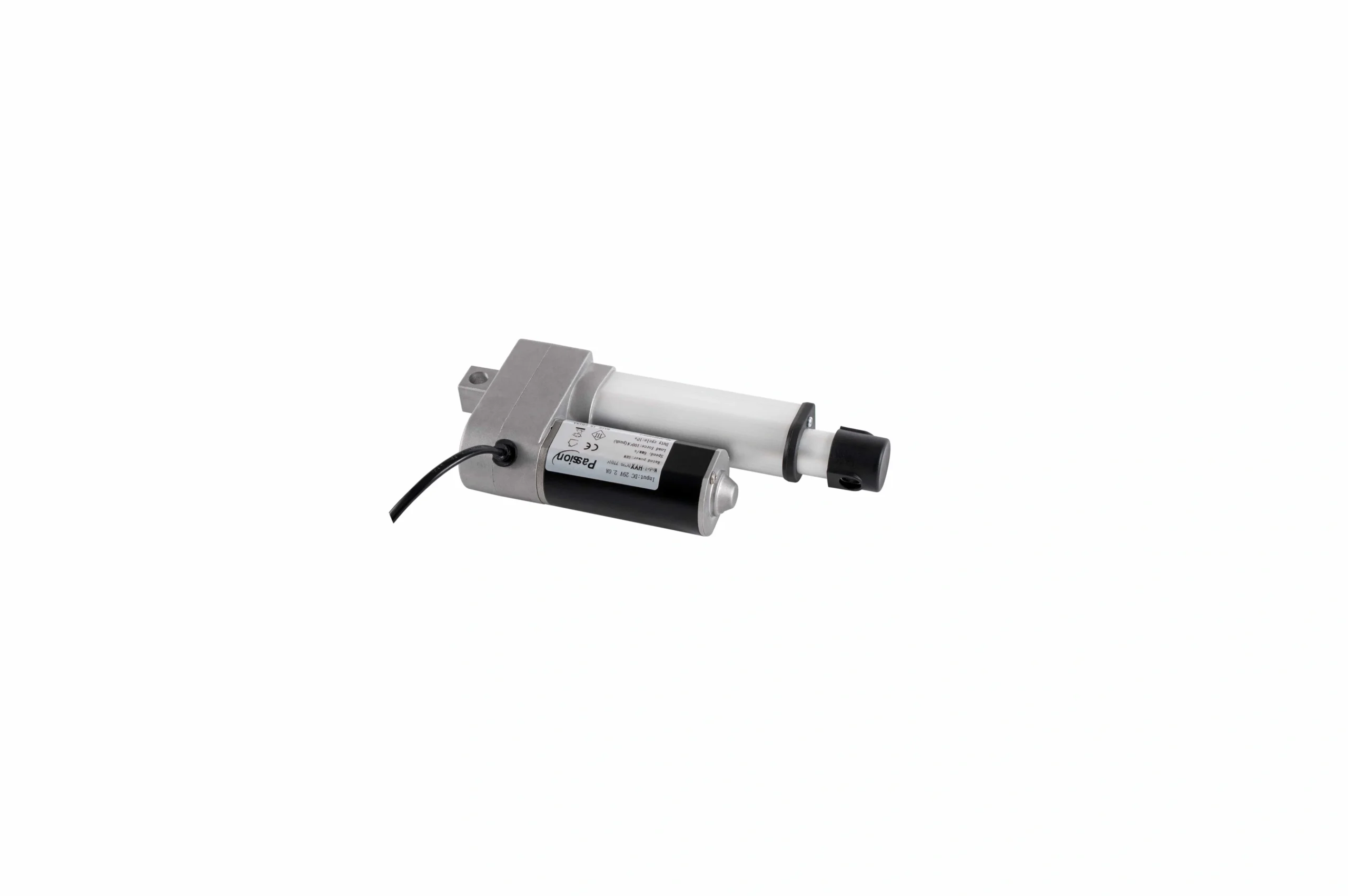
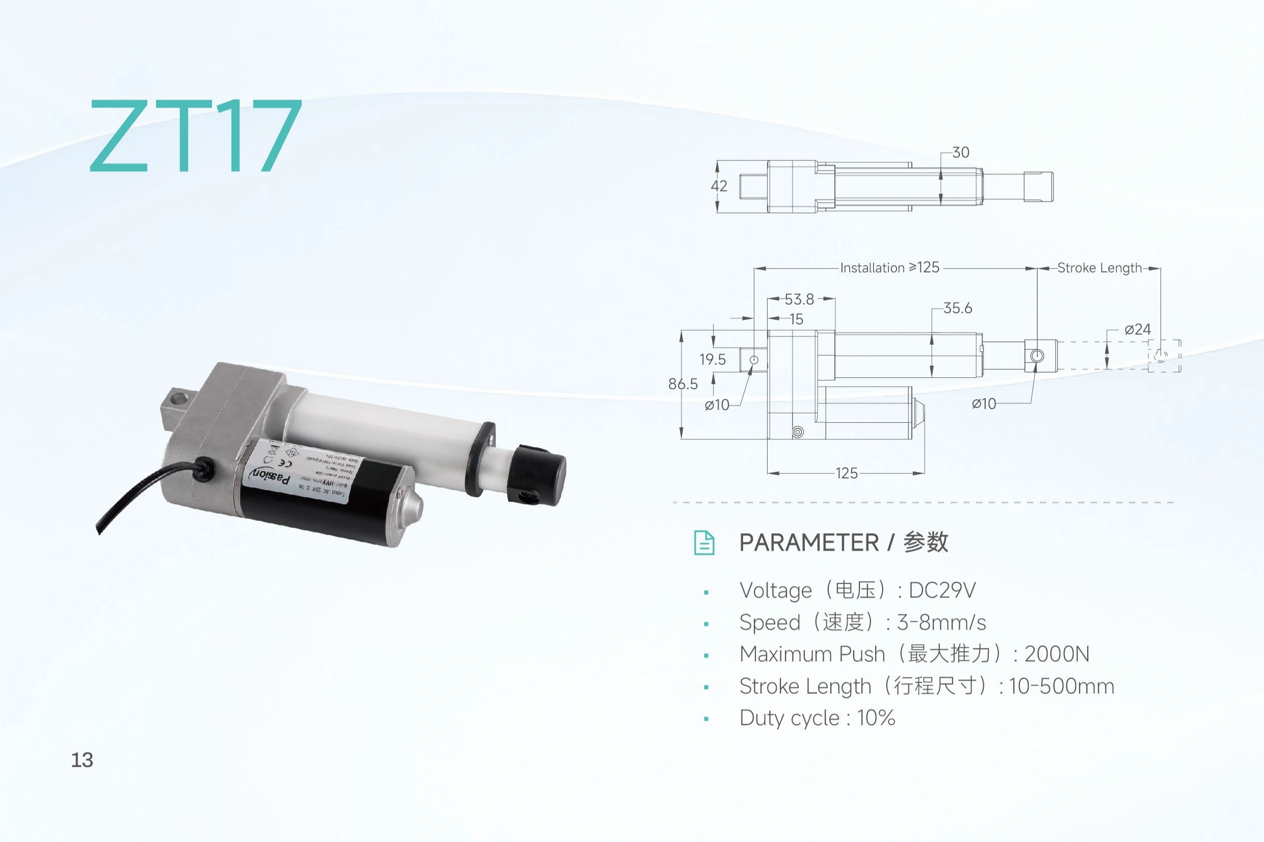
ZT17
- MAX PUSH
- 2,000 N
- SPEED
- 3–8 mm/s
- STROKE
- 10–500 mm
- INSTALL REF.
- ≥125 mm
The bars compare published maximum fields independently; they do not imply a combined operating point.
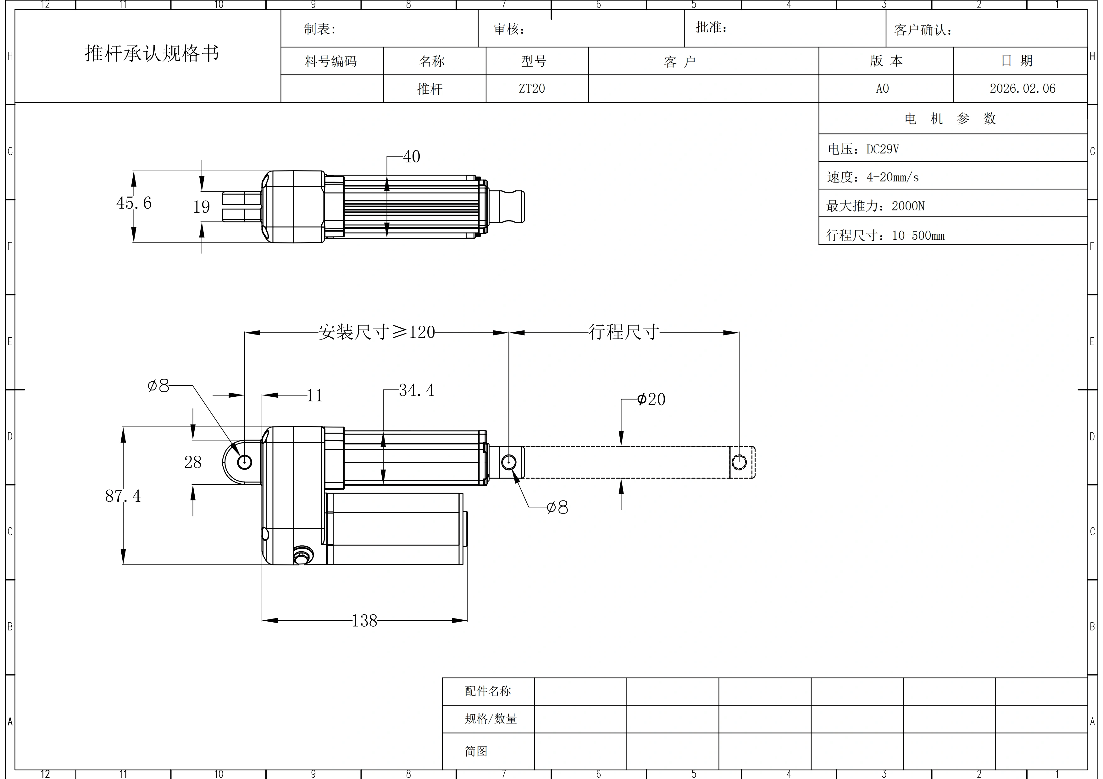
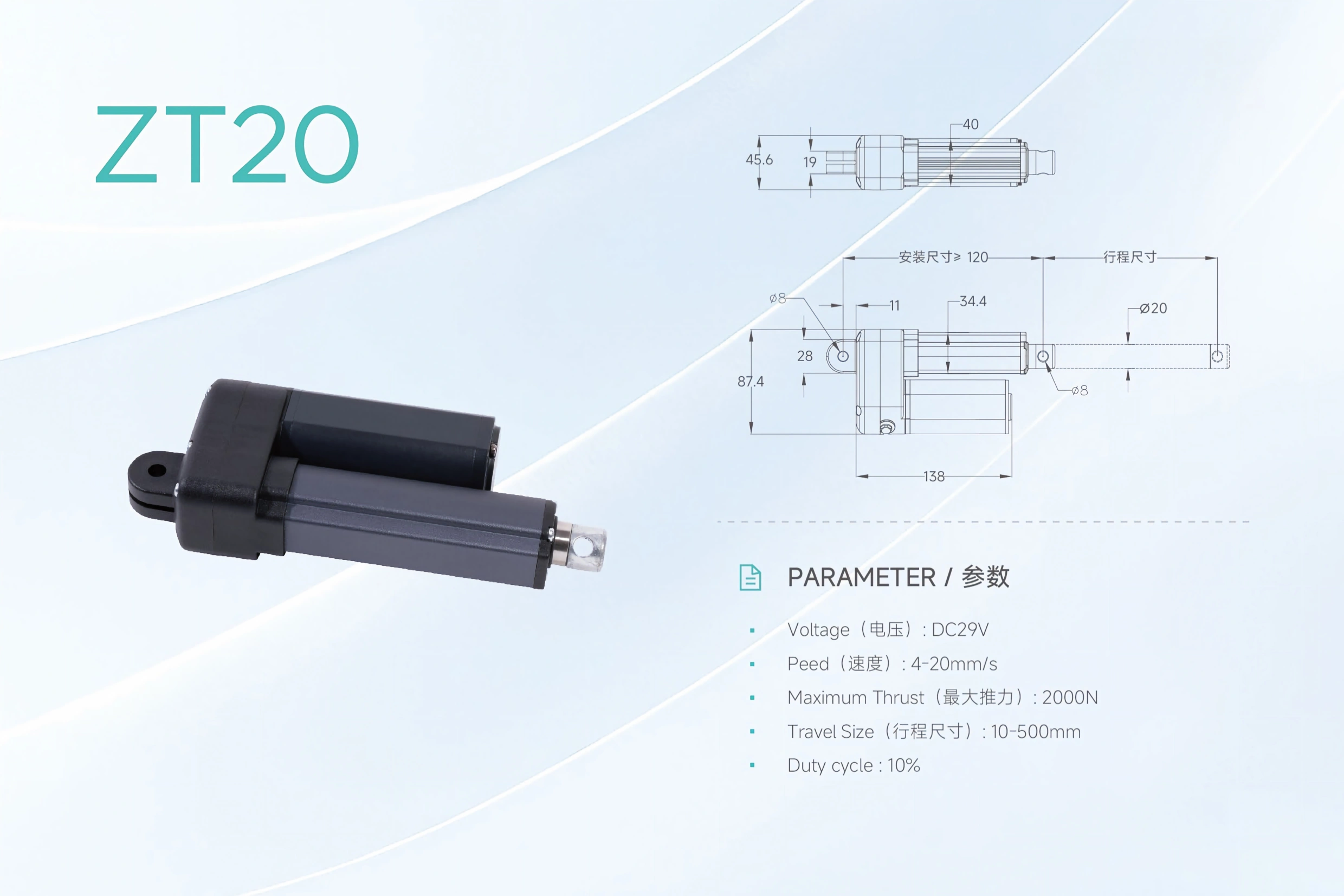
ZT20
- MAX PUSH
- 2,000 N
- SPEED
- 4–20 mm/s
- STROKE
- 10–500 mm
- INSTALL REF.
- ≥120 mm
The bars compare published maximum fields independently; they do not imply a combined operating point.
The published family data covers maximum push ratings from 2,000 N to 6,000 N, speed ranges from 3 to 40 mm/s, and stroke options from 10 to 1,000 mm.
These are family-level envelopes, not one combined operating point. Model selection should be based on the required working load, loaded speed, stroke, installation space, cycle and control requirements together.
For the broader product family structure, see our linear actuator range .
Seven models, one technical frame.
| Model | Voltage | Maximum Push | Published Speed | Stroke Range | Published Duty Cycle | Preliminary Installation Dimension |
|---|---|---|---|---|---|---|
| ZT01 | DC 29V | 6,000 N | 6–40 mm/s | 10–600 mm | 10% | ≥150 mm |
| ZT06 | DC 29V | 6,000 N | 6–40 mm/s | 10–600 mm | 10% | ≥150 mm |
| ZT09 | DC 29V | 3,000 N | 6–40 mm/s | 10–600 mm | 10% | ≥140 mm |
| ZT11 | DC 29V | 2,000 N | 5–30 mm/s | 10–500 mm | 10% | ≥130 mm |
| ZT12 | DC 29V | 2,500 N | 6–40 mm/s | 10–1,000 mm | 10% | ≥140 mm |
| ZT17 | DC 29V | 2,000 N | 3–8 mm/s | 10–500 mm | 10% | ≥125 mm |
| ZT20 | DC 29V | 2,000 N | 4–20 mm/s | 10–500 mm | 10% | ≥120 mm |
Selection note: maximum push, maximum published speed and maximum stroke must not be assumed to be available together. A force-speed table and configuration-level test conditions are not yet part of the local evidence package.
Keep comparison visual, not only numerical.
These product references help distinguish the family as you move from published limits to installation and system context. They are visual references, not proof of a shared configuration.
Read the envelope as a system, not as a headline number.
/ READ THE RANGES Published limits are not one operating point.
A high speed linear actuator should be selected by the required motion at the actual load, not by the top speed number alone. The ZT family data currently provides published speed ranges, but it does not provide loaded-speed curves or a verified relationship between thrust, speed and stroke for each configuration.
Use the listed values to shortlist a model, then confirm the operating point before release:
- required working load and whether it acts mainly in push, pull or both directions;
- required speed under that load;
- stroke and full moving envelope;
- expected starts per hour and run/rest pattern;
- ambient conditions;
- required control and feedback behavior.
The published 10% duty-cycle value is useful as a comparison field, but the current product record does not define the run/rest basis or test conditions. For continuous or frequent cycling, include the real cycle profile in the inquiry.
/ INSTALL + SYSTEM Fit the actuator into the mechanism and the 29V system.
Stroke is only one mechanical dimension. The actuator also needs to fit when retracted, move through the full travel without interference and remain aligned with the load path.
The local product record includes preliminary installation dimensions from ≥120 mm to ≥150 mm depending on model, plus model-specific tube, housing and mounting-hole dimensions. Treat these values as early design references rather than released toleranced drawings.
Before design freeze, confirm:
- retracted installation space;
- required stroke;
- mounting-pin diameter and bracket geometry;
- surrounding clearance through the full motion;
- whether the load is guided so the actuator is not expected to carry significant side load;
- the released drawing revision for the selected configuration.
The actuator is only one part of the motion system. Power capacity, controller behavior, feedback, limits, connector style and cable routing should be reviewed together.
If you are building a complete 29V system, compare the available 29V power supply options and confirm the selected actuator’s current demand and connector requirements before pairing components.
The current ZT family evidence does not verify a universal controller, feedback type, limit-switch behavior, connector pinout or synchronization tolerance across all seven models. Those items should be confirmed for the exact project configuration.
Shortlist with the real project inputs.
| Selection Input | What to Provide |
|---|---|
| Load direction | Push, pull, vertical lift, horizontal push or angled mechanism |
| Working load | Normal and worst-case load, not only nominal mass |
| Loaded speed | Required mm/s at the working load |
| Stroke | Required travel in mm |
| Installation space | Available retracted length and surrounding envelope |
| Cycle | Run time, rest time and starts per hour |
| Environment | Indoor/outdoor, dust, moisture, temperature and cleaning exposure |
| Control | Simple extend/retract, position feedback, multi-actuator coordination or other logic |
| Quantity | Prototype, pilot batch and expected production volume |
| Documents | Drawing, CAD, wiring, test report or other release documents required |
Common family-level questions.
Which ZT model has the highest published push rating?
ZT01 and ZT06 each list a maximum push rating of 6,000 N in the local product record. The required speed and stroke still need to be checked for the actual operating point.
Which model offers the longest published stroke?
ZT12 lists a stroke range of 10–1,000 mm. The other models in the current family record list maximum strokes of 500 mm or 600 mm.
Which models list speeds up to 40 mm/s?
ZT01, ZT06, ZT09 and ZT12 each publish a 6–40 mm/s range. The current record does not provide loaded-speed curves, so 40 mm/s should not be assumed at maximum push.
Does every ZT model use 29V DC?
Yes. The local product record lists DC 29V for all seven models covered on this page.
Can I select a model only by thrust?
No. Shortlisting should also include loaded speed, stroke, installation space, cycle, load direction, environment and control requirements.
Are feedback, ingress rating and certifications the same across the series?
The current local evidence does not establish one universal specification for those attributes. Confirm them for the exact model and project configuration.
Bring the operating point, not just the headline force.
Send us your working load, load direction, loaded speed, stroke, installation space, cycle, control requirements, quantity and required documents. We can use that information to review the ZT shortlist before you freeze the mechanical design.
Request a ZT configuration review