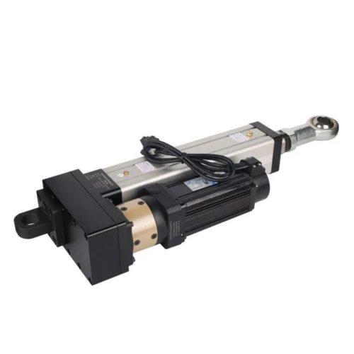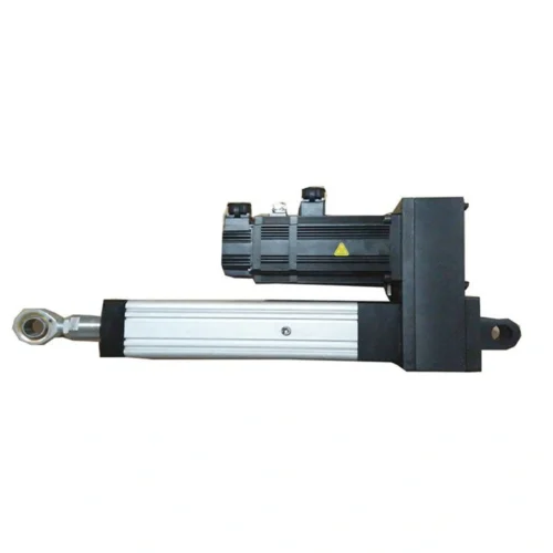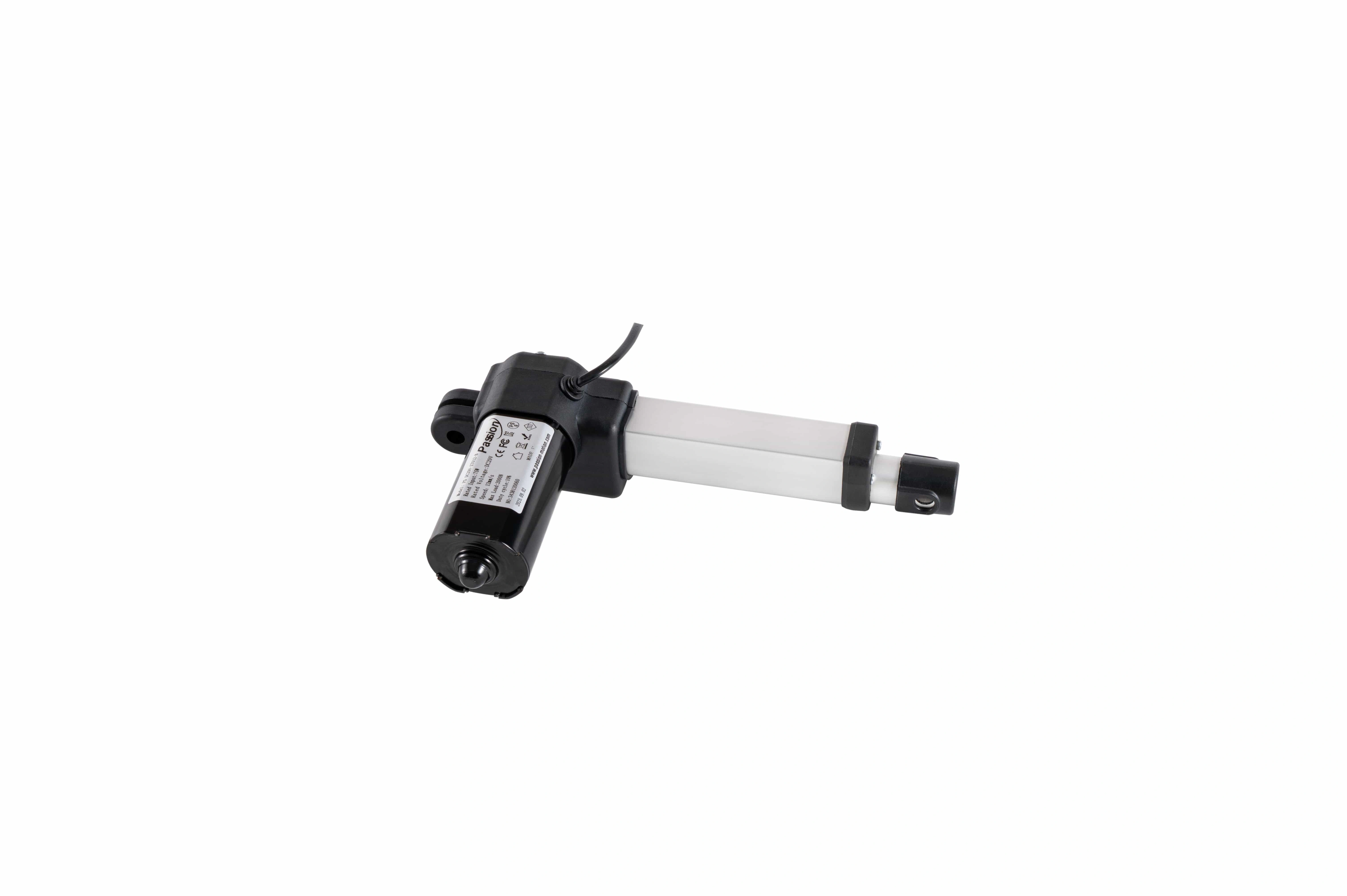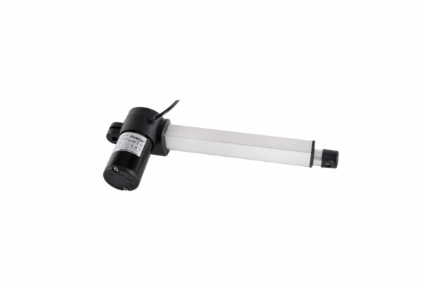
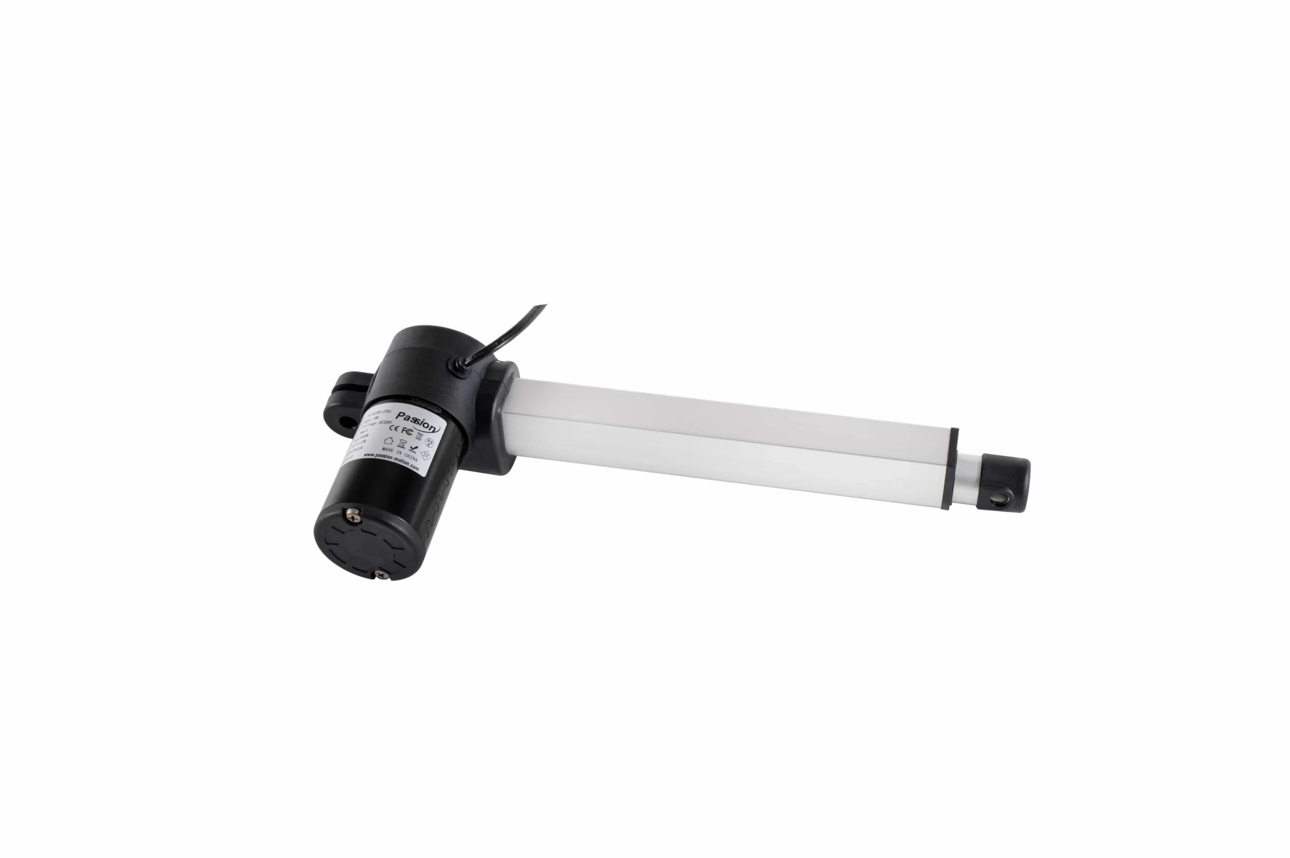
ZT01 29V Linear Actuator
29V Linear Actuator
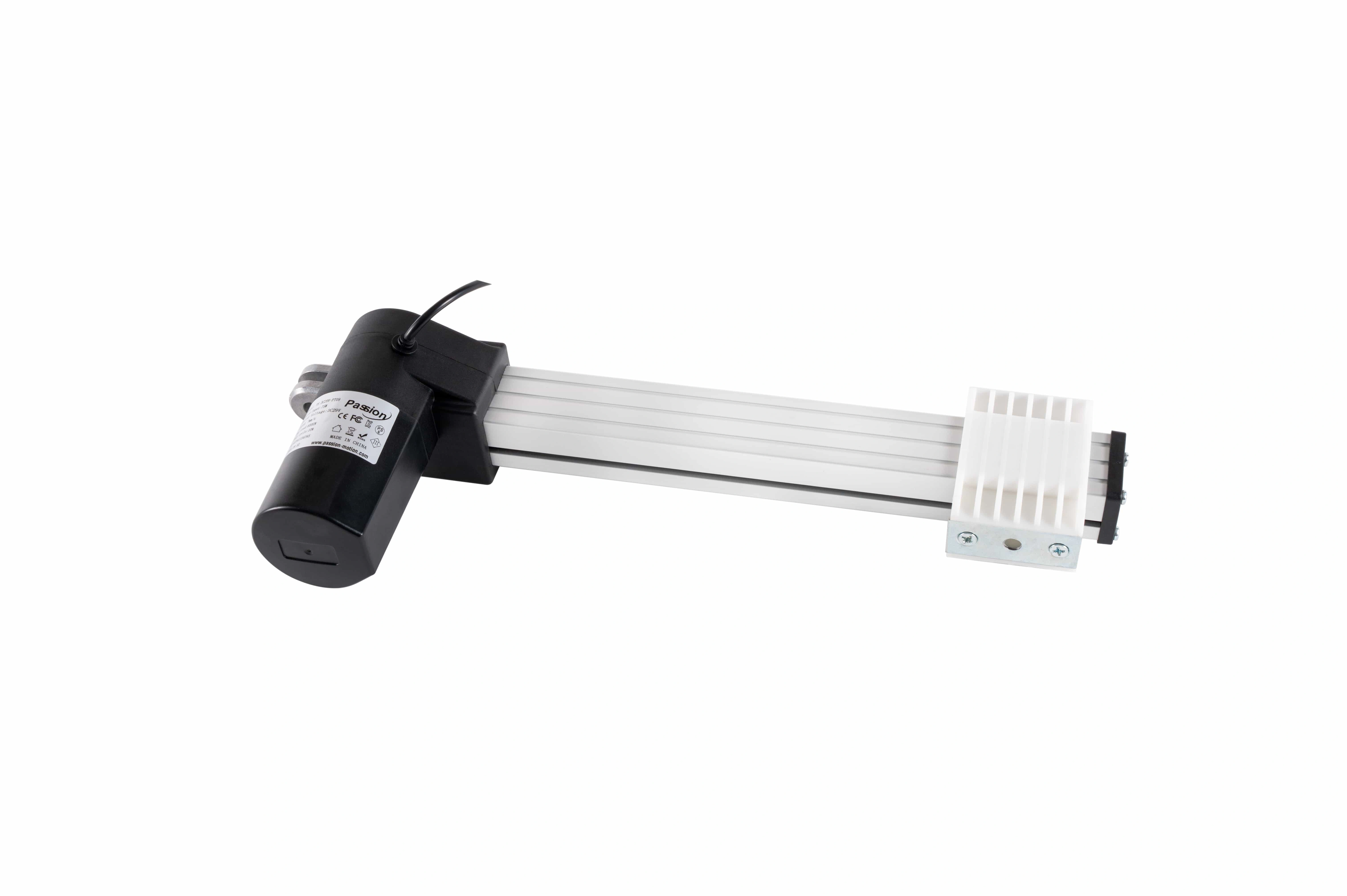
Compact push-rod motion for machine integration, with published ranges covering up to 6,000 N push, 40 mm/s speed and 600 mm stroke. Final configuration is reviewed as one operating point.
mm/s speed
mm stroke
Published product data
·
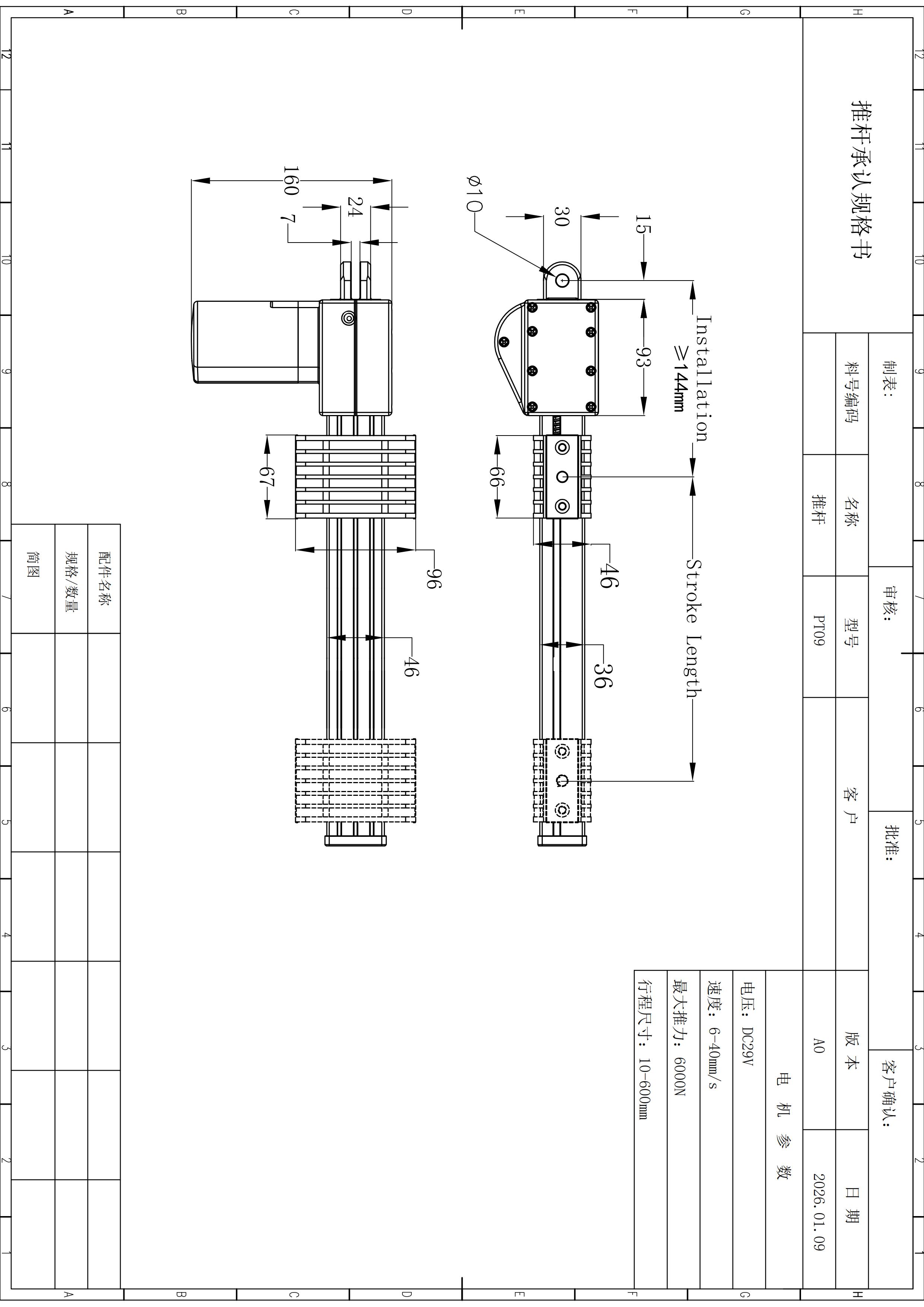
Drawing-reference dimensions
·
Configuration review required
ZT01 PRODUCT STORY
Built for compact linear motion.
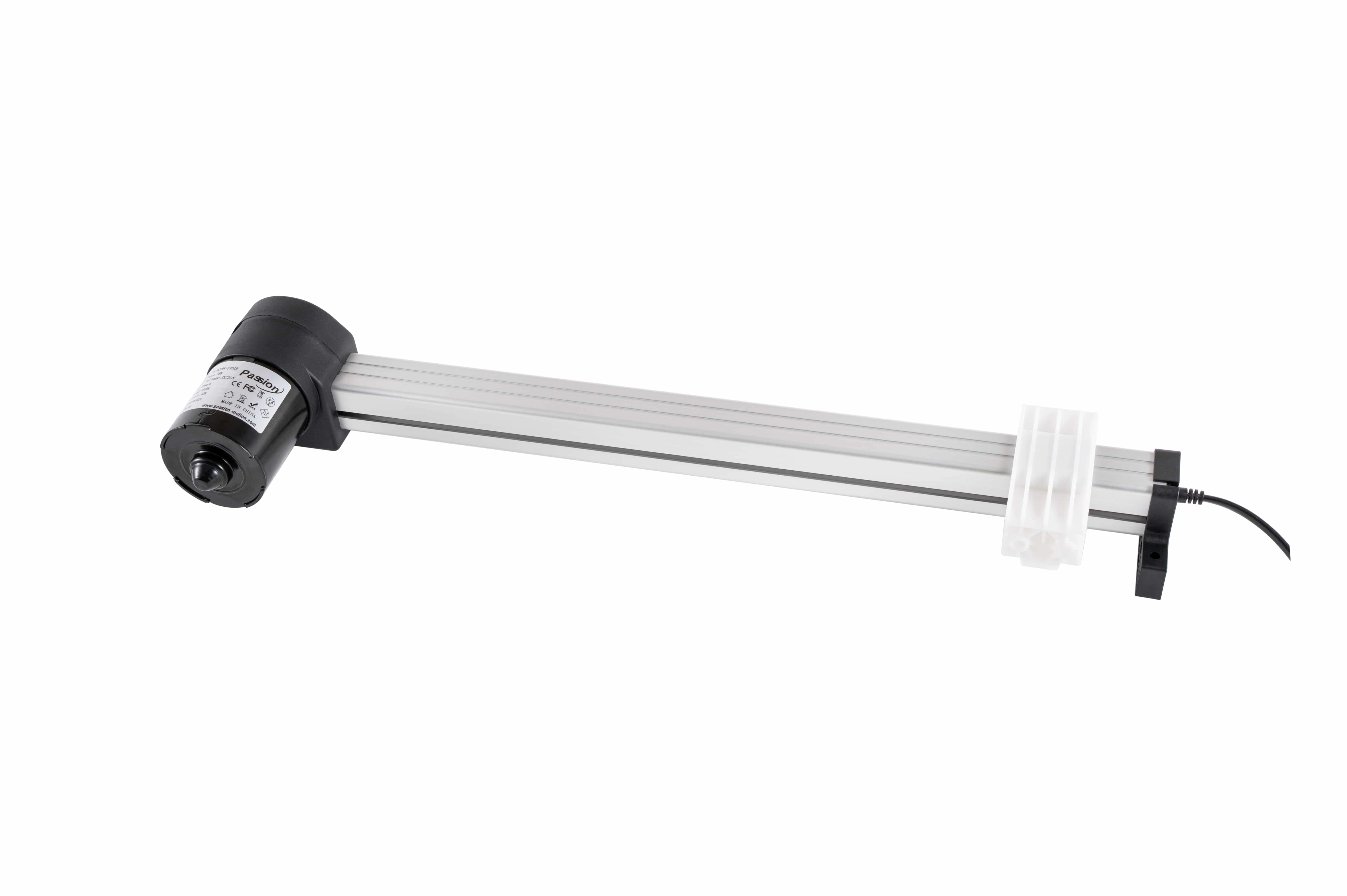
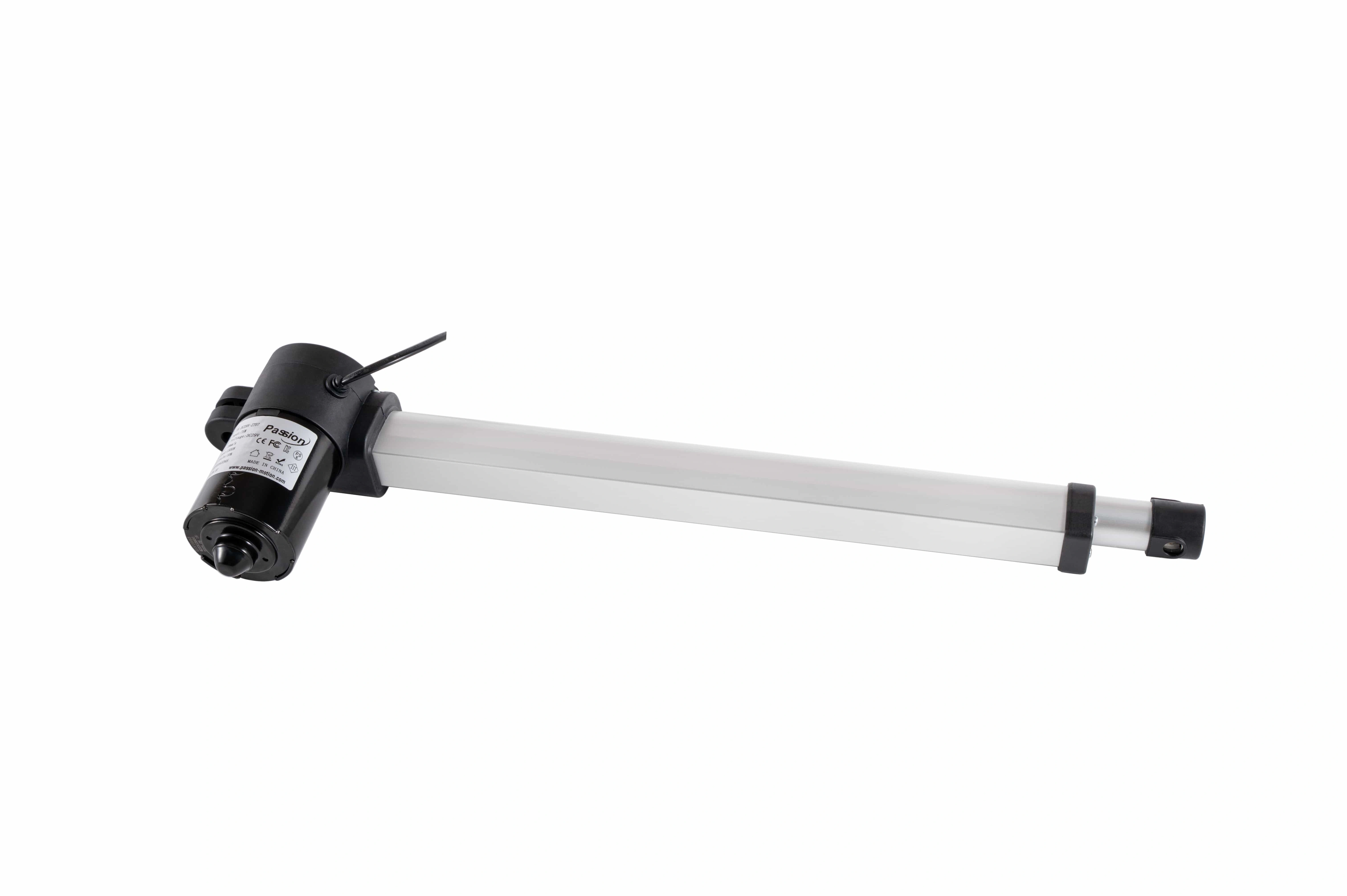
ZT01 packages a 29V push-rod drive into a compact actuator format for projects that need controlled linear travel without jumping immediately to a larger electric-cylinder architecture.
The key engineering question is not whether each headline maximum exists independently. It is whether your working load, loaded speed, stroke, cycle and installation envelope belong to one workable configuration.
Verified data
The numbers that define the screening range.
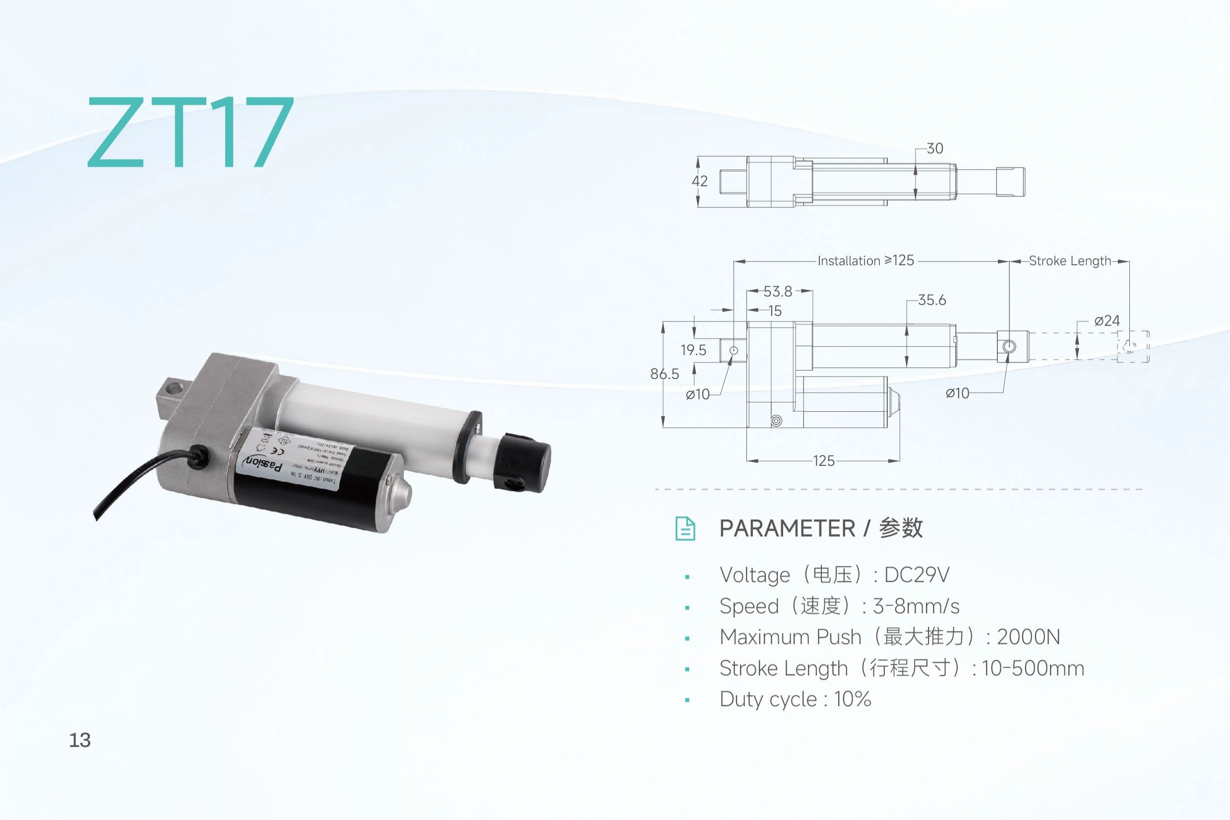
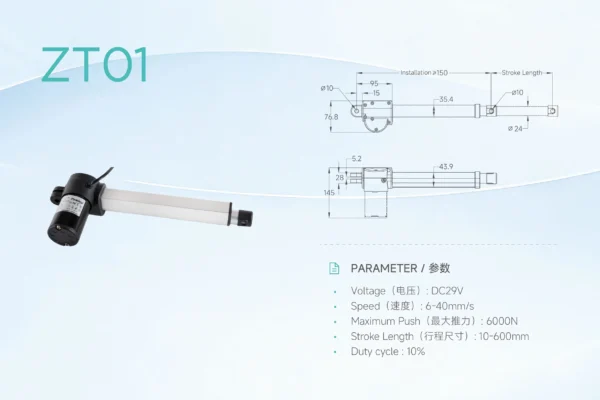
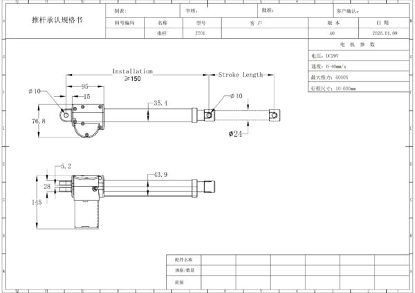
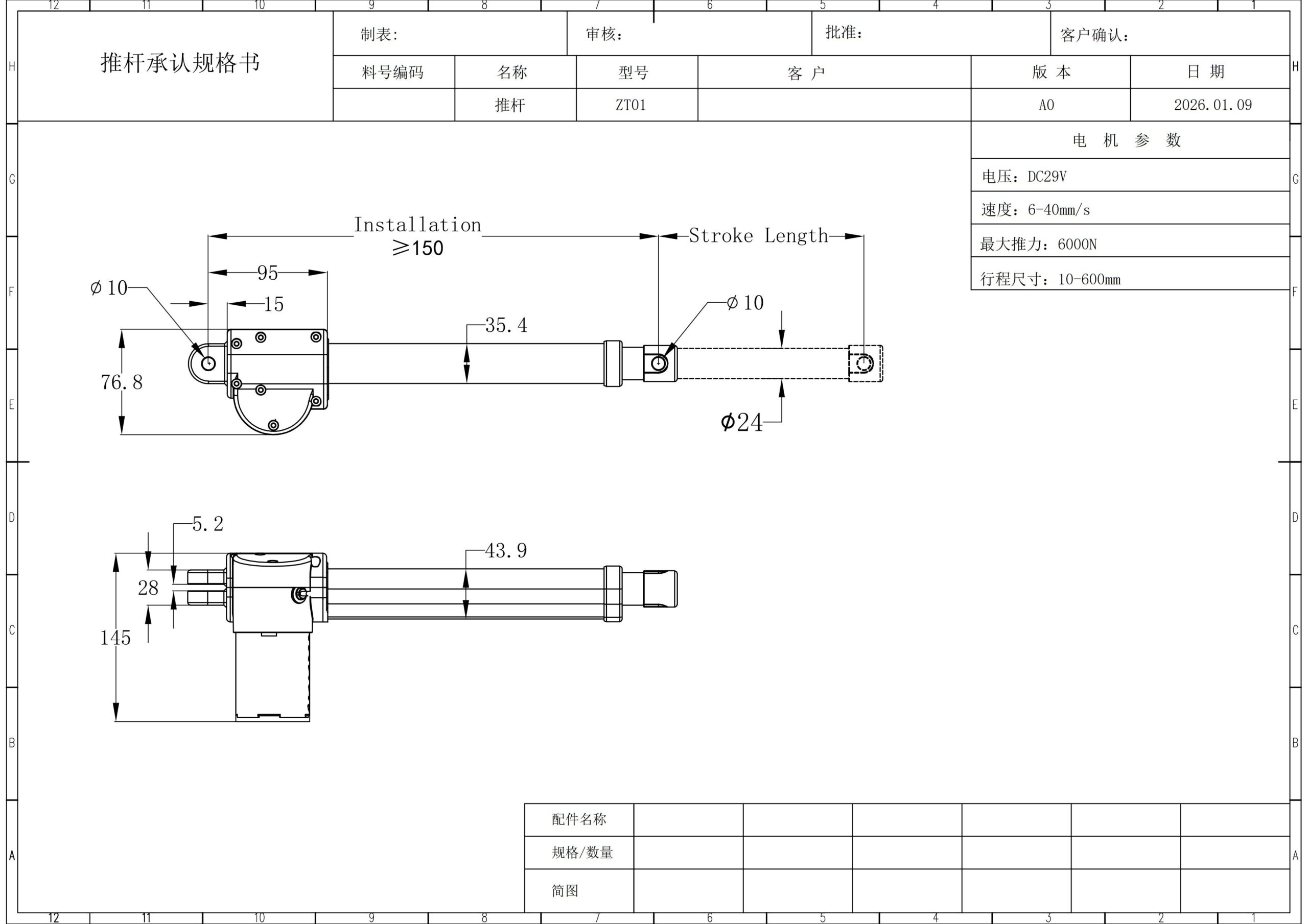
These are published ZT01 values and drawing-reference dimensions. They are screening limits, not proof that every endpoint can be combined.
| Parameter | Published value | Selection note |
|---|---|---|
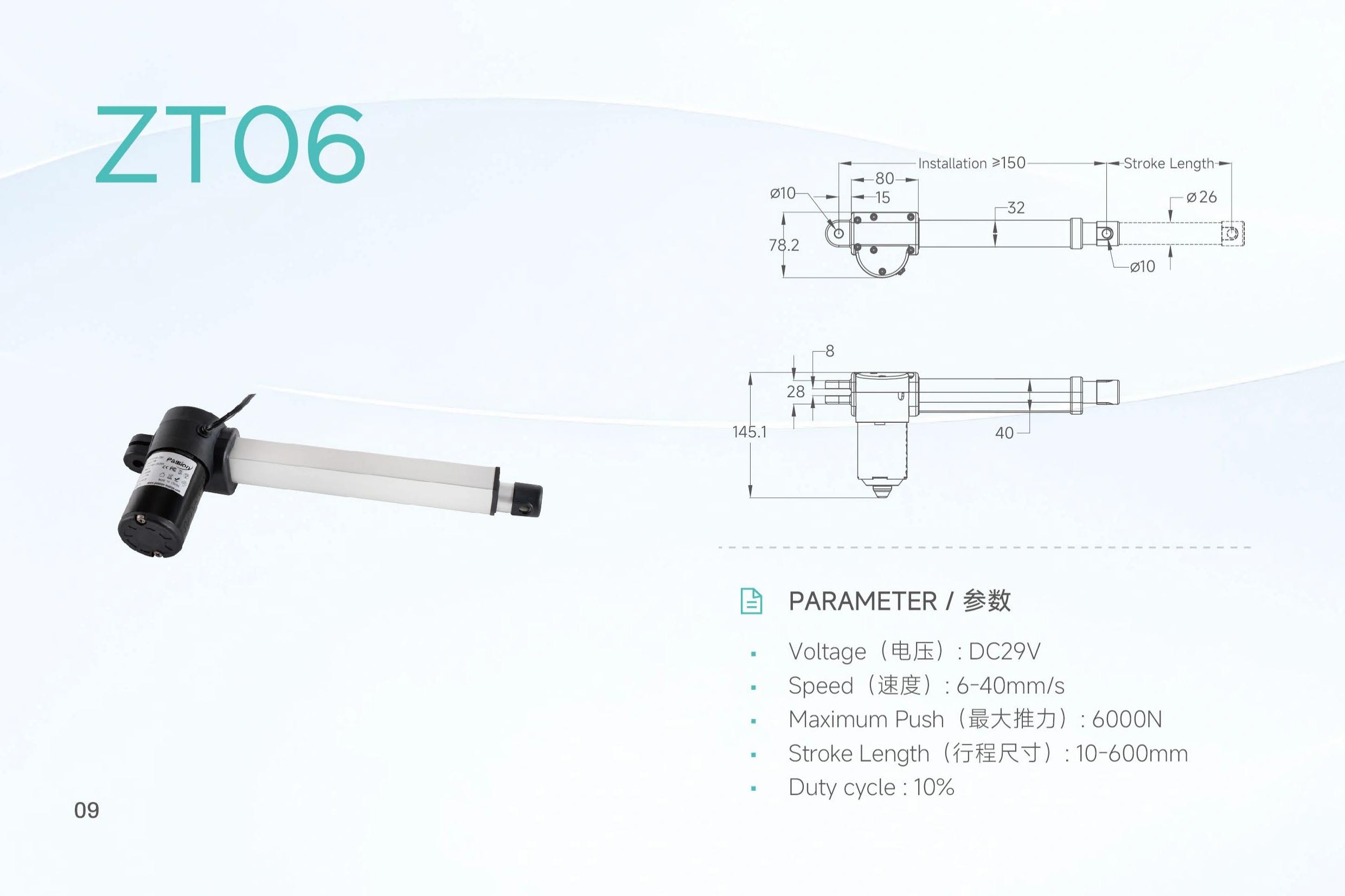
| Input voltage | DC 29V | Confirm the complete power and control arrangement before release. |
| Maximum push | 6,000 N | Maximum push rating; a separate pull-force value is not published in the local source. |
| Speed | 6–40 mm/s | Published range. Specify required loaded speed for model review. |
| Stroke | 10–600 mm | Confirm selected stroke together with required force and speed. |
| Duty cycle | 10% | The local source provides the percentage but not a detailed test-time basis. |
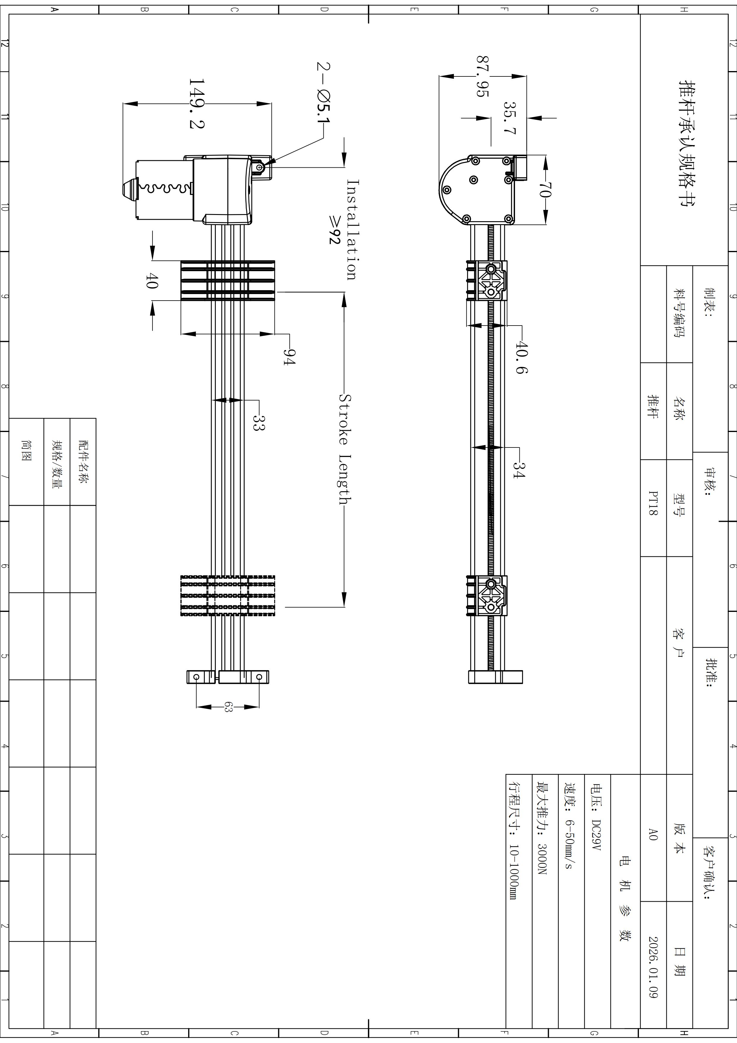
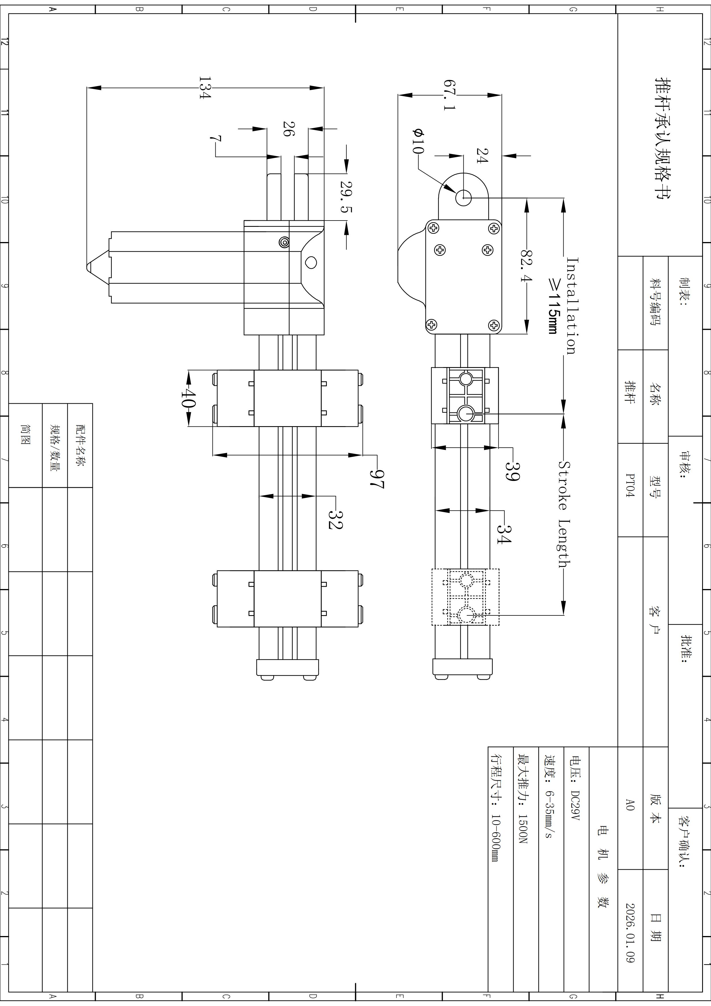
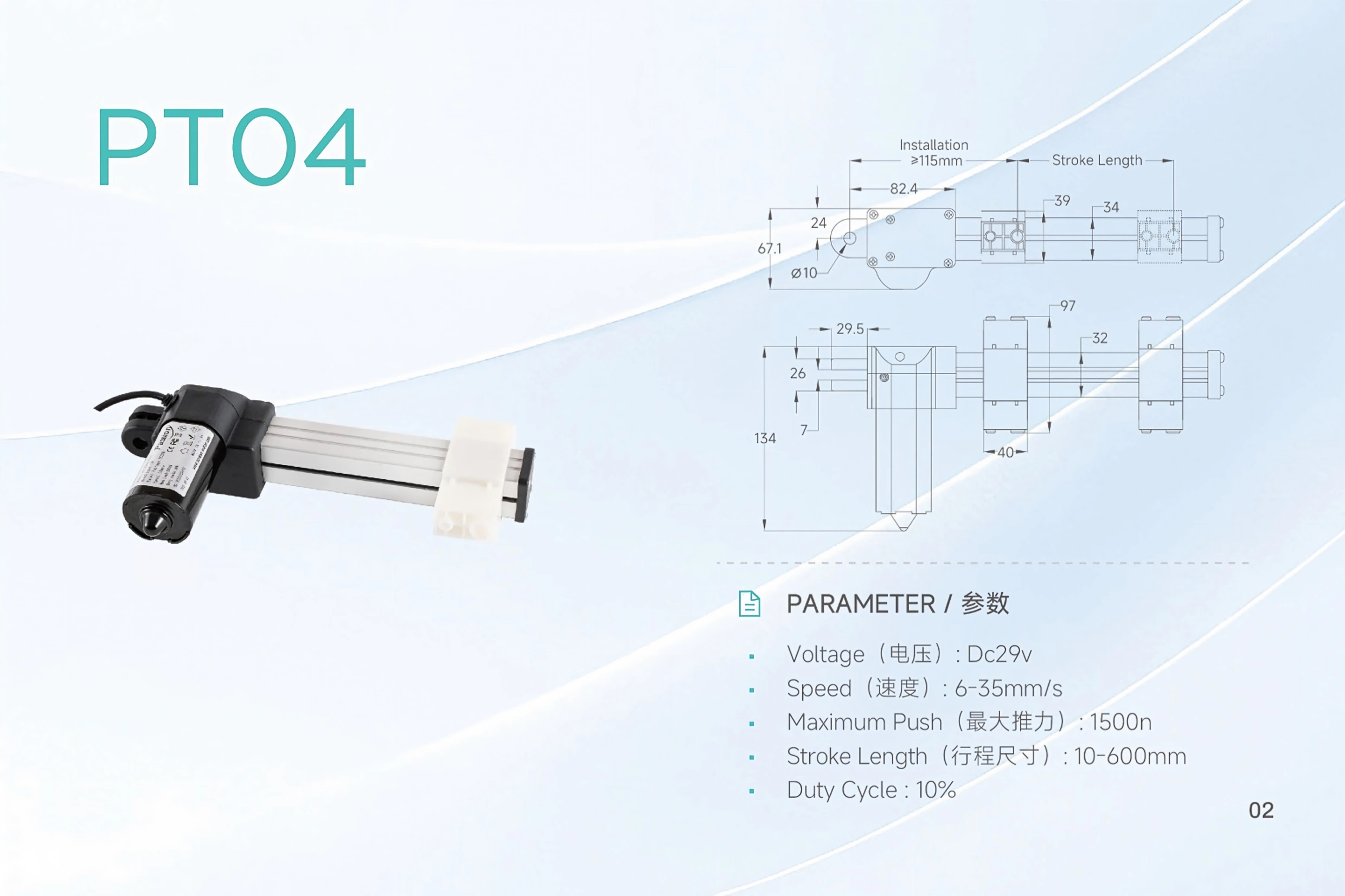
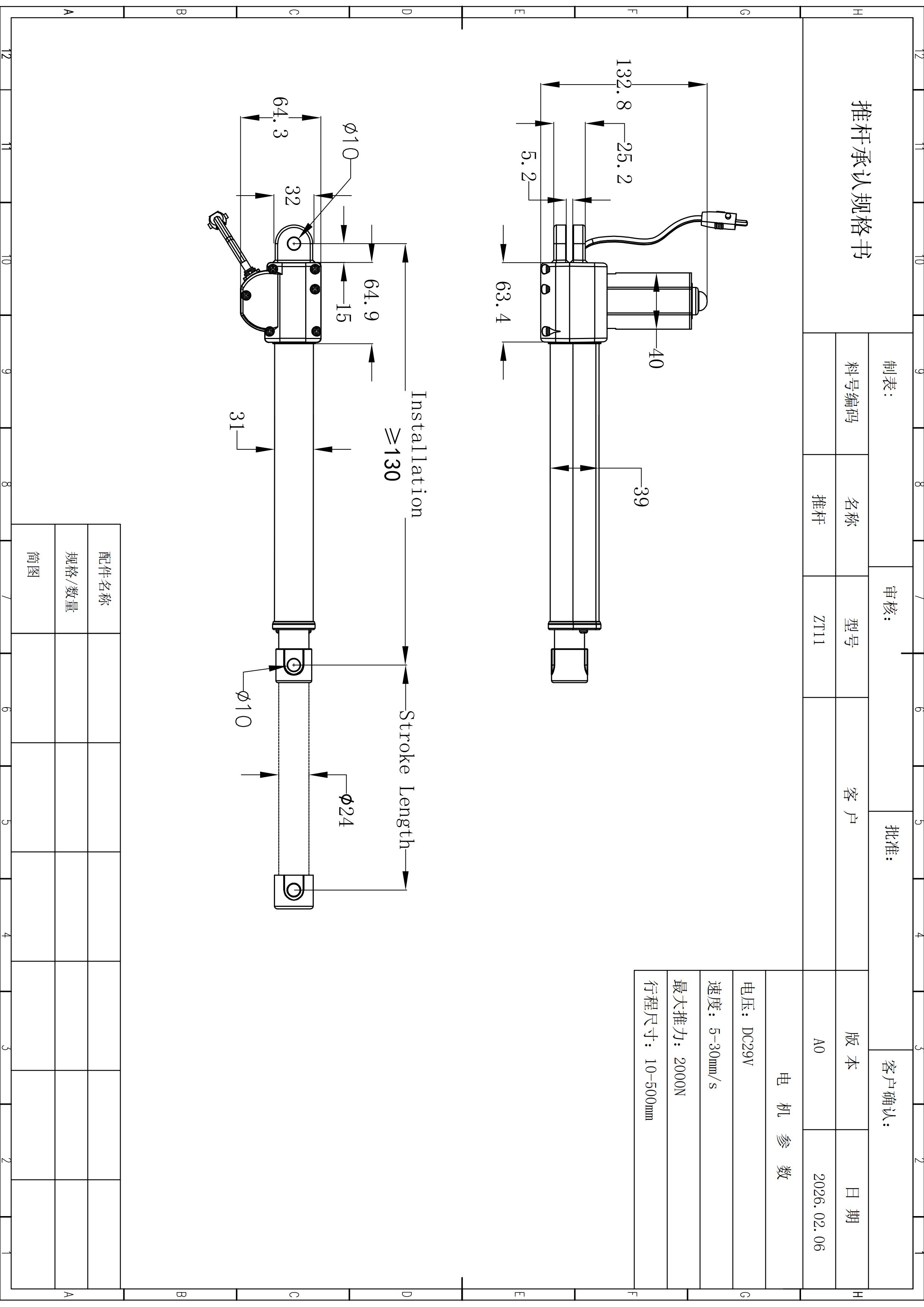
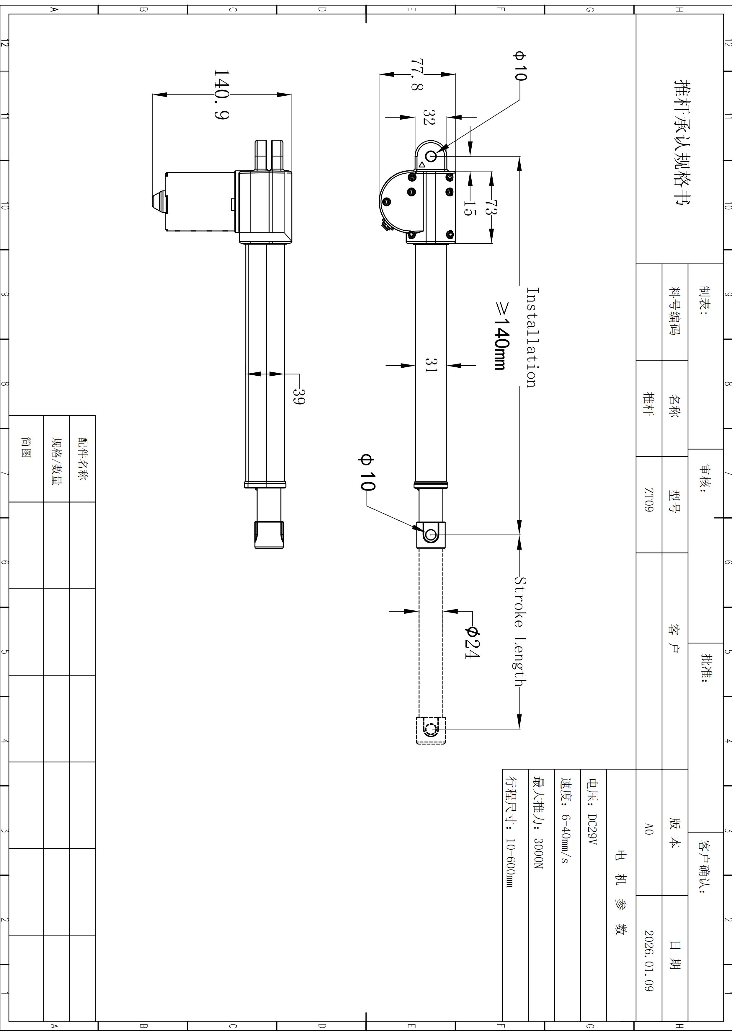
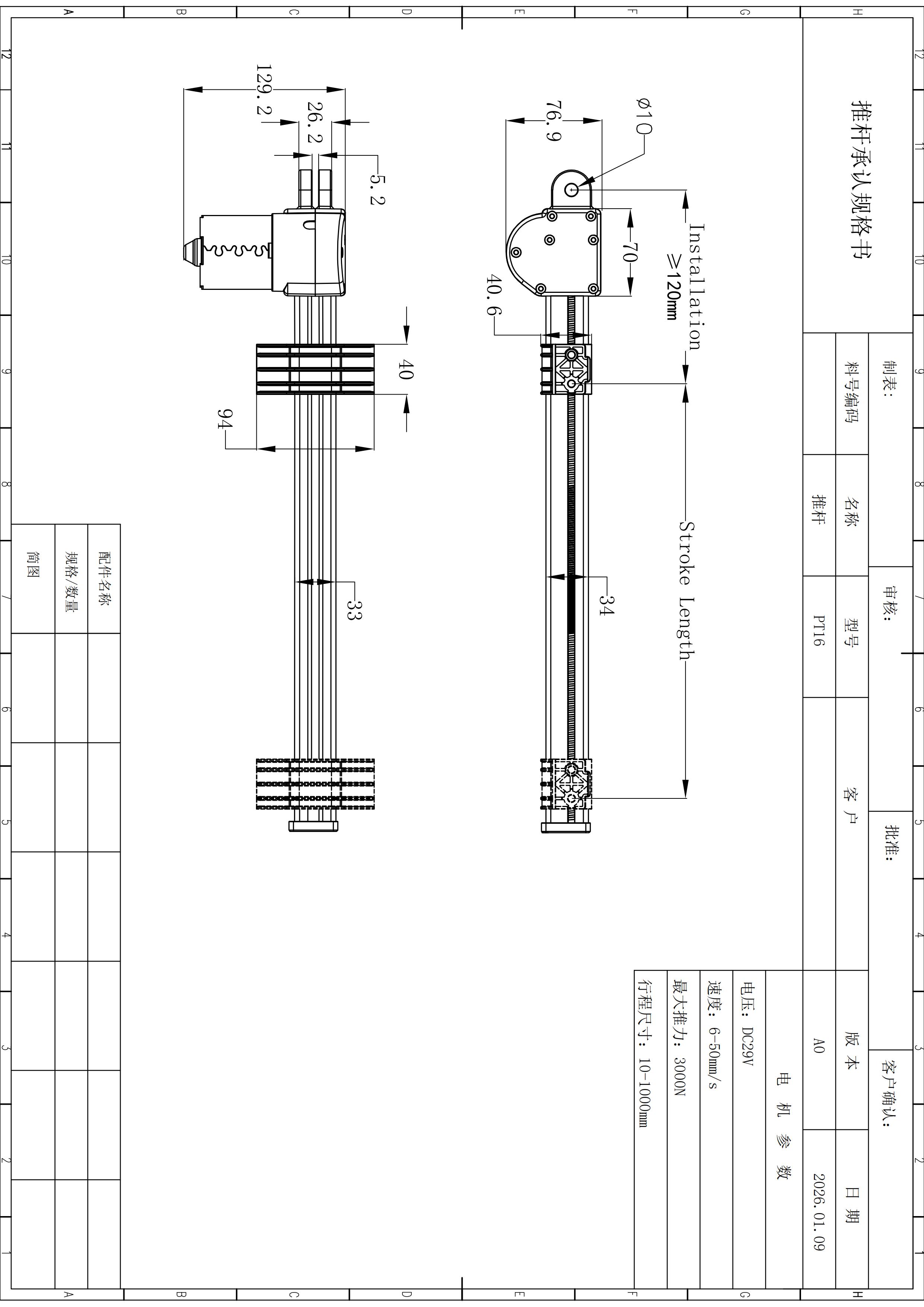
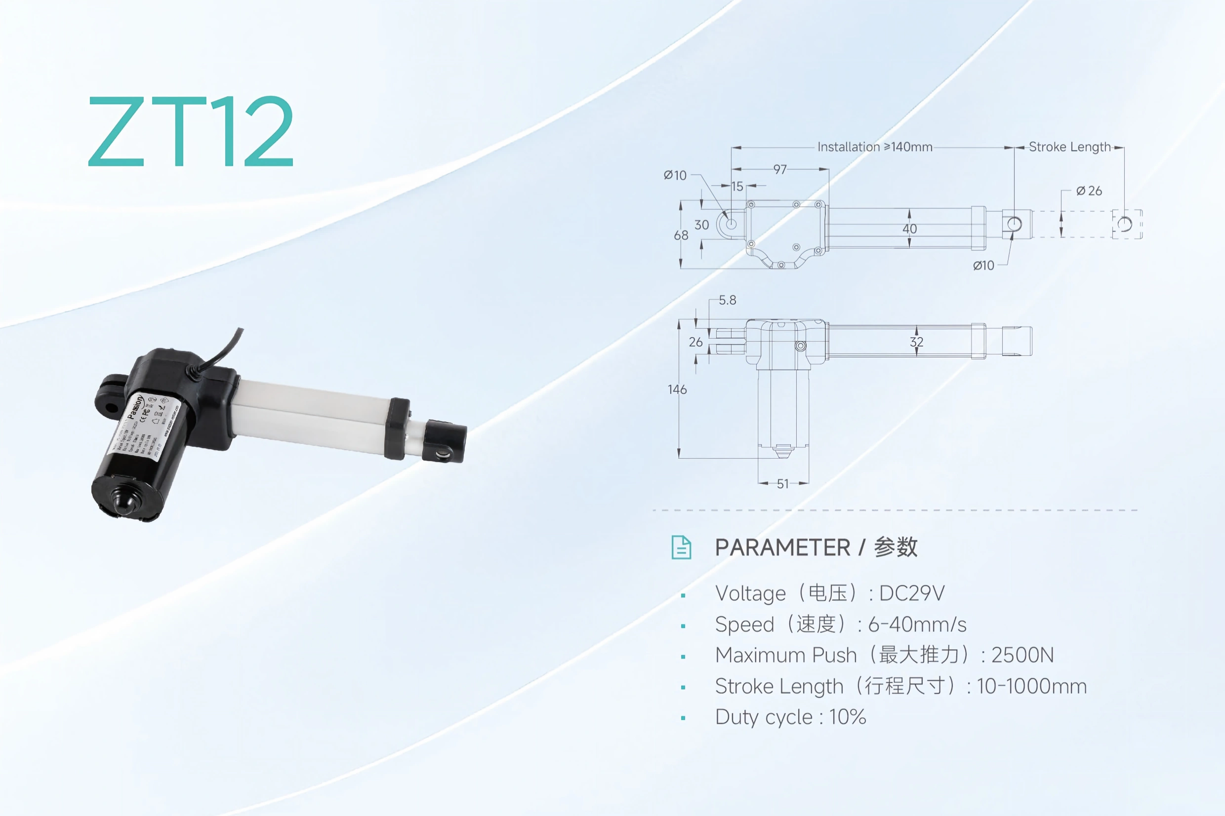
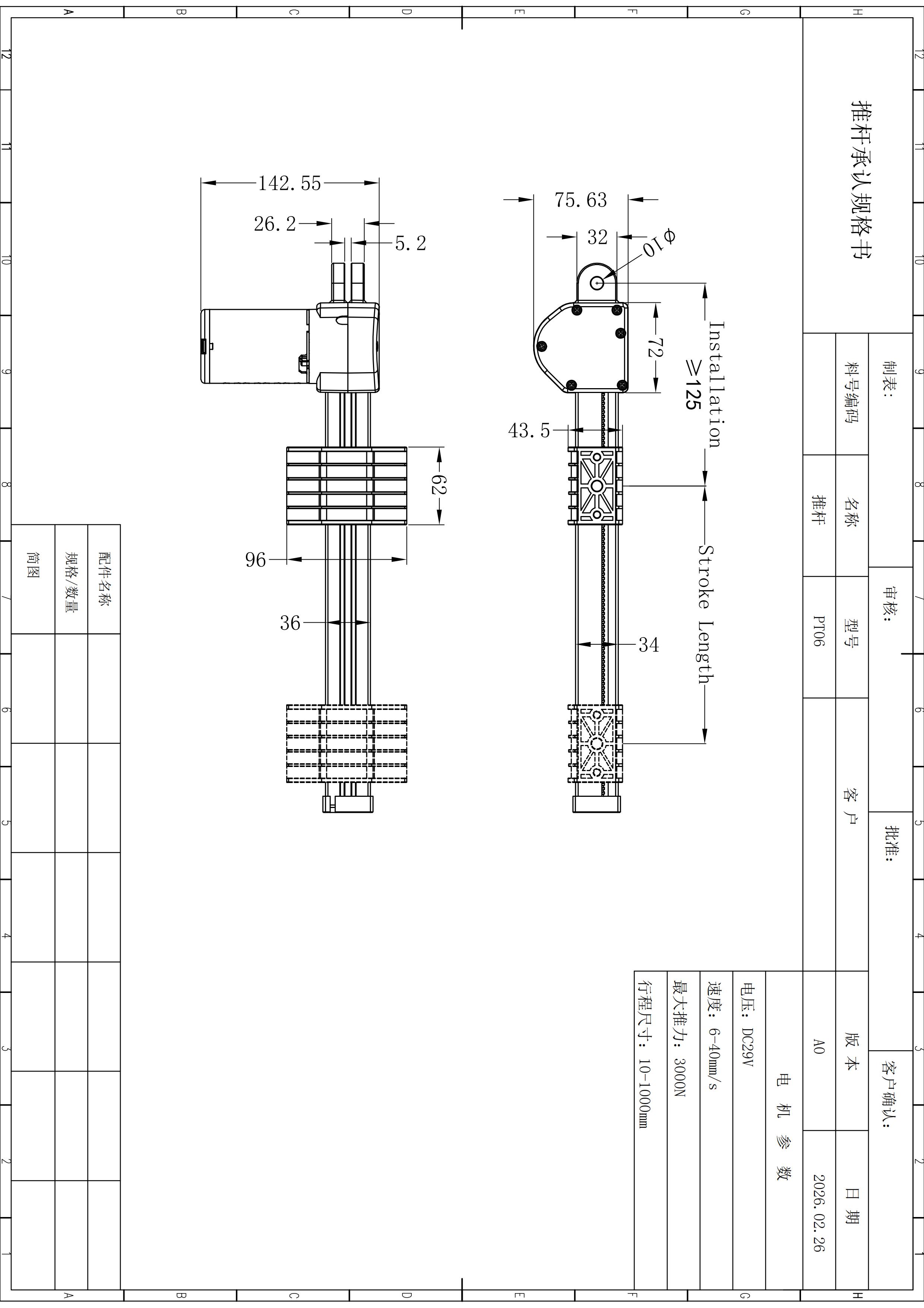
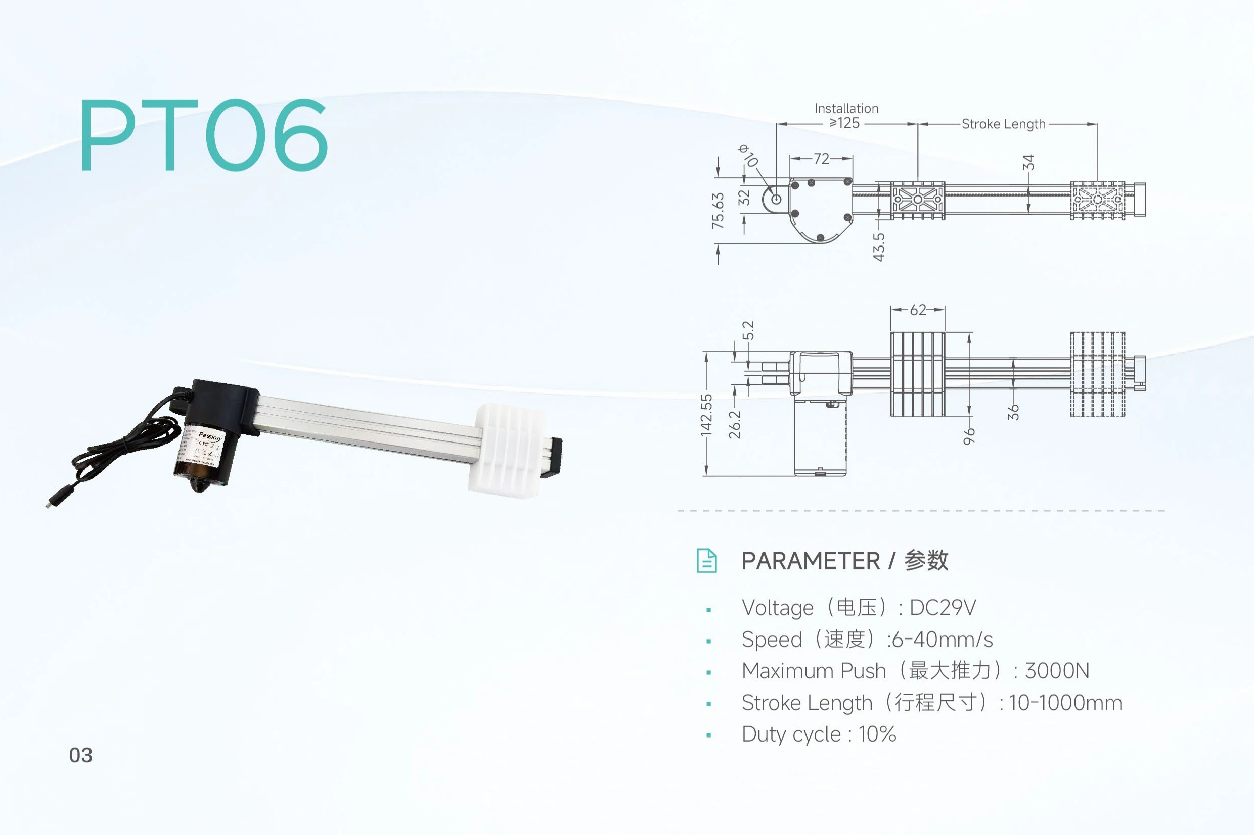
| Minimum installation dimension | ≥150 mm | Drawing-reference value; do not use it as a stroke-to-closed-length formula. |
| Cylinder outer diameter | Ø24 mm | Drawing-reference value. |
| Pin-hole diameter | Ø10 mm | Applies to listed mounting holes in the local drawing summary. |
| Motor housing height | 145 mm | Drawing-reference value. |
| Motor base width | 76.8 mm | Drawing-reference value. |
Configuration boundary
One operating point.
Not three maximums.
The current source confirms a 6,000 N maximum push, a speed range to 40 mm/s and stroke options to 600 mm. It does not publish a force-versus-speed pairing table or prove that every endpoint occurs together.
-
01
Define the actual working load.
Normal and peak load belong in the same review as travel speed.
-
02
Specify loaded speed, not free-travel expectation.
The published speed range alone does not establish performance at maximum push.
-
03
Review stroke, cycle and installation together.
Long travel and operating frequency can change the configuration decision.
Mechanical integration
Check the envelope before release.
Send the available retracted space, mounting constraints and preferred pin orientation. Final integration should use the current controlled drawing rather than dimensions inferred from page copy.
- Minimum installation dimension ≥150 mm
- Cylinder outer diameter Ø24 mm
- Mounting pin holes Ø10 mm
- Motor housing height 145 mm
- Motor base width 76.8 mm
Designing the electrical architecture at the same time? Review 29V power supply options.
Model review
What engineering actually needs.
A useful inquiry describes the mechanism and operating condition. Four input groups are enough to move from a headline model to a meaningful configuration review.
01
Motion
Load direction, normal and peak working load, required loaded speed, and stroke.
02
Mechanical
Retracted envelope, mounting limits, pin orientation, and surrounding mechanism constraints.
03
Duty & environment
Moves per cycle, cycles per hour, on/off pattern, temperature, dust, moisture, and exposure.
04
System
29V supply, connector and cable needs, controls, feedback, documentation, quantity, and timeline.
Selection posture
A strong candidate—when the project stays inside the evidence.
Use this as a screening framework, not an engineering release approval.
Good starting point
The requirement aligns with the published range.
- A 29V linear push drive suits the system architecture.
- Required push stays at or below the 6,000 N published maximum.
- Required speed and stroke sit inside the published ranges.
- The mechanism can accommodate the drawing-reference envelope.
Engineering review required
The decision depends on data the headline table does not establish.
- A specific loaded speed near maximum push is required.
- Pull force, IP level, lifetime or positioning accuracy is decision-critical.
- A particular feedback, synchronization or control interface is required.
- Model-specific compliance documents are needed for release.
ZT01 FAQ
Questions that matter before release.
Is ZT01 rated for 6,000 N?
Can ZT01 run at 40 mm/s while pushing 6,000 N?
Is the full 600 mm stroke available with every force and speed option?
What voltage does ZT01 use?
What should I send for a quote?
Engineering review / RFQ
Bring the operating point. We’ll review the configuration.
Working load + loaded speed + stroke + installation space + cycle + control requirements is enough to begin a useful ZT01 review.
Move from product screening to a defined engineering discussion.
Submit ZT01 ProjectFinal configuration remains subject to project review and controlled technical data.