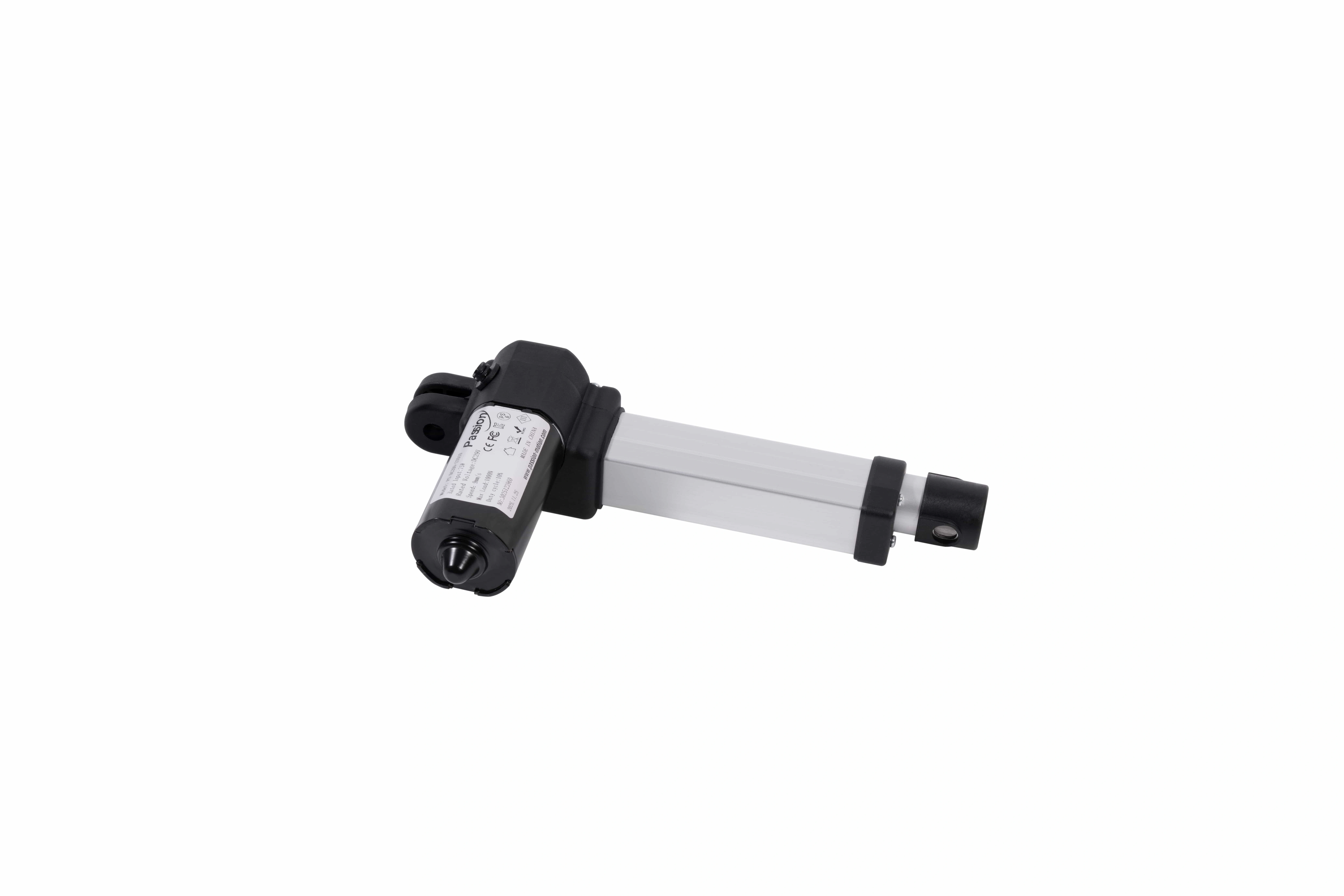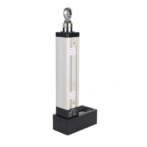

PT04 Linear Actuator: 1500N, 600mm Stroke
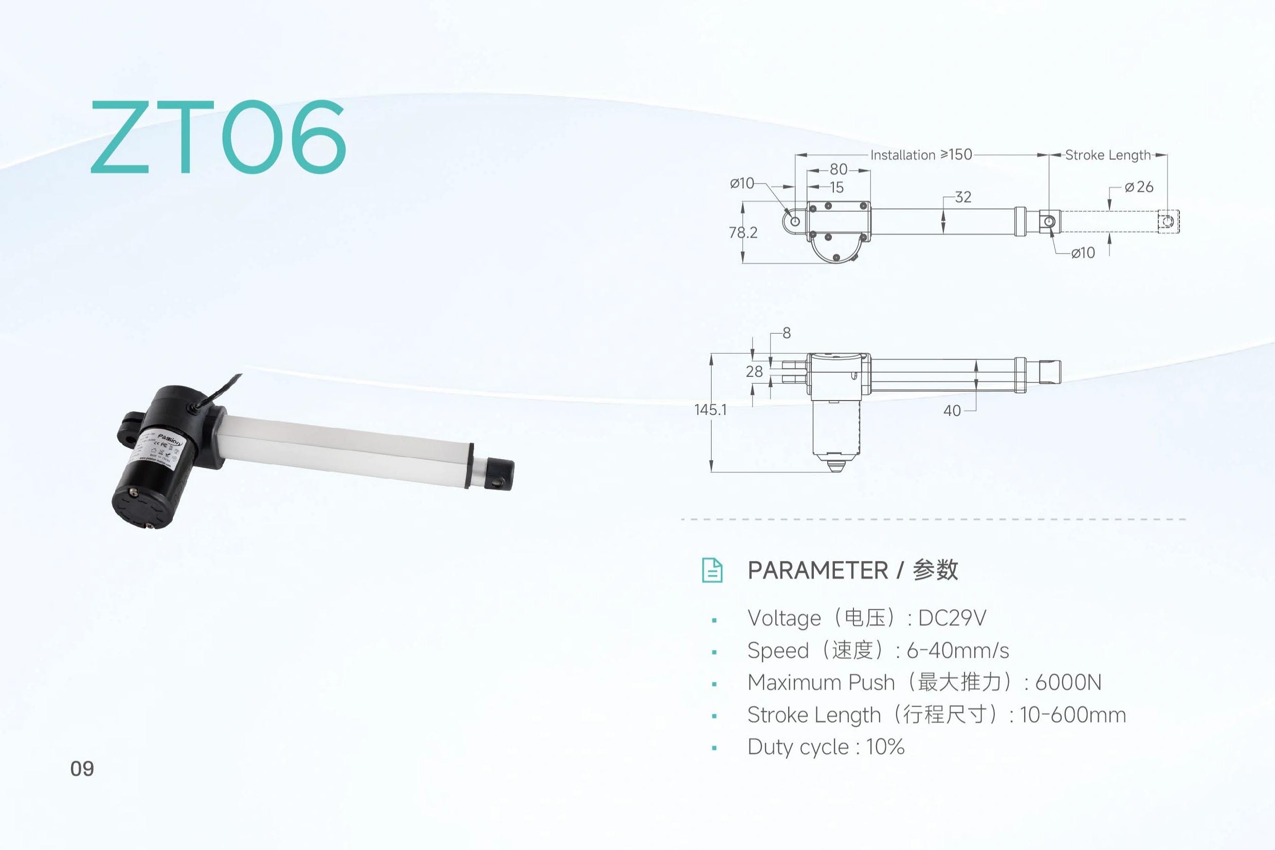
Review PT04 specifications including DC 29V, up to 1500N push force, 6–35 mm/s speed, 10–600 mm stroke, duty cycle and mounting dimensions.
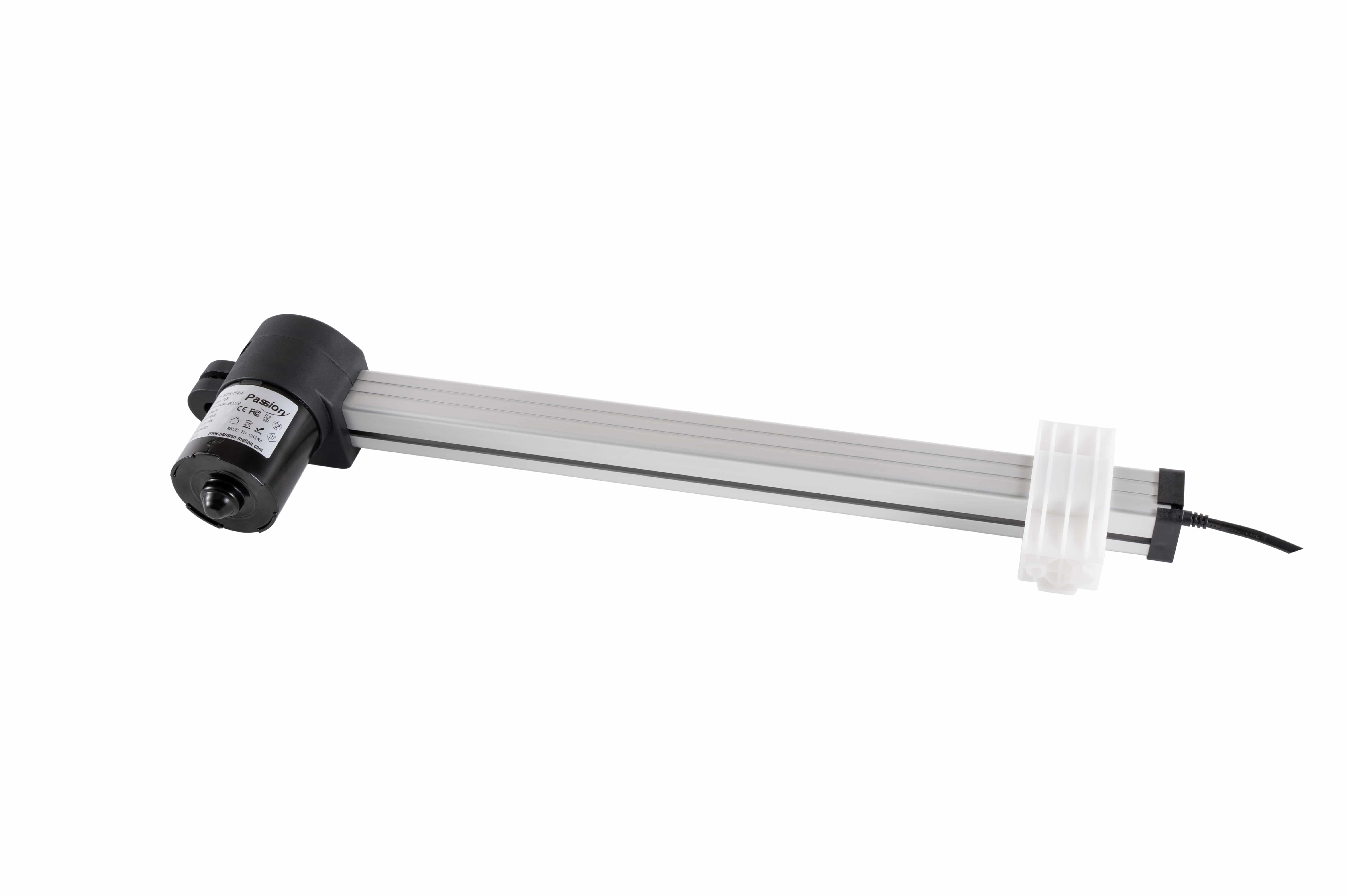
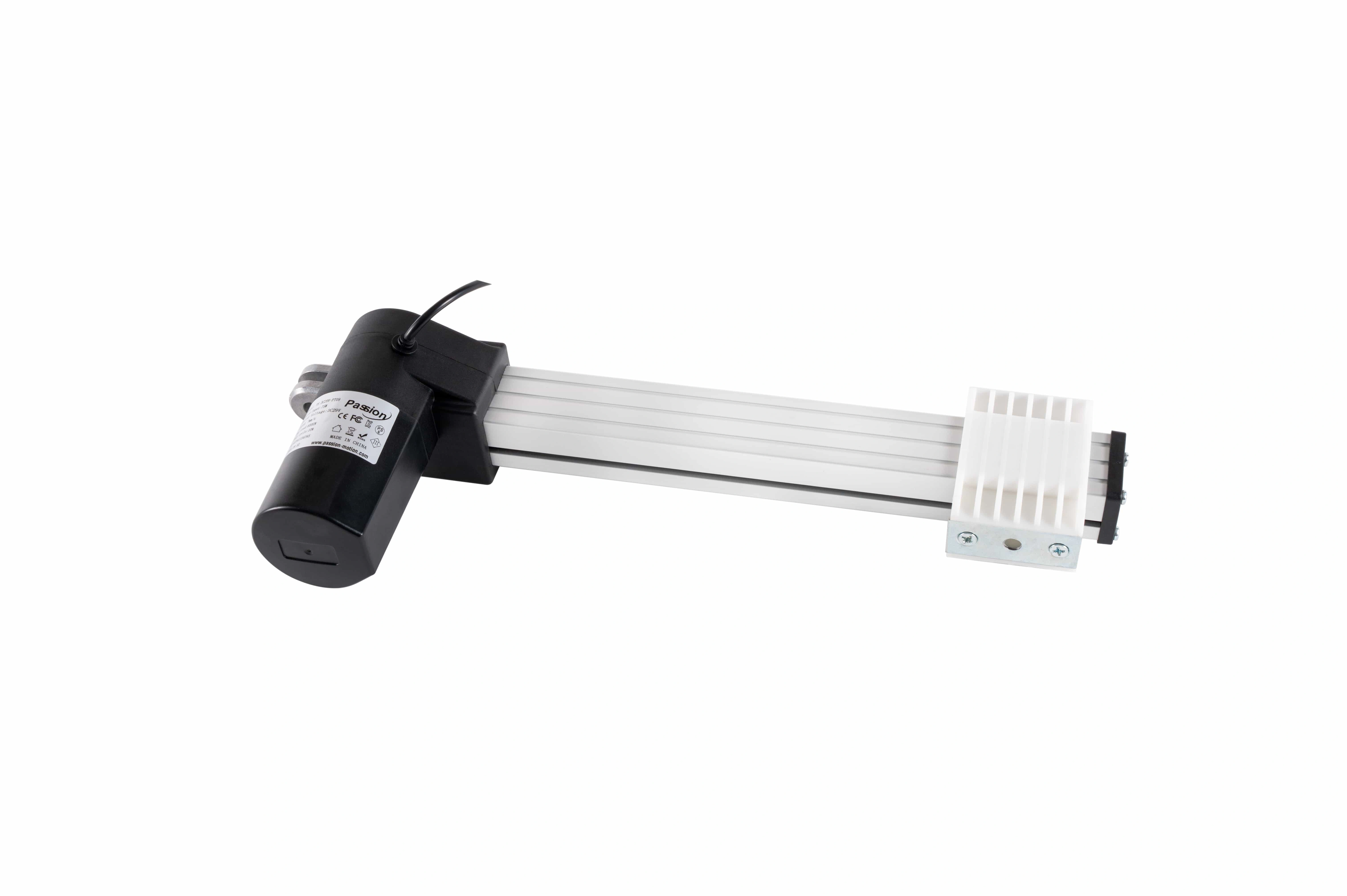
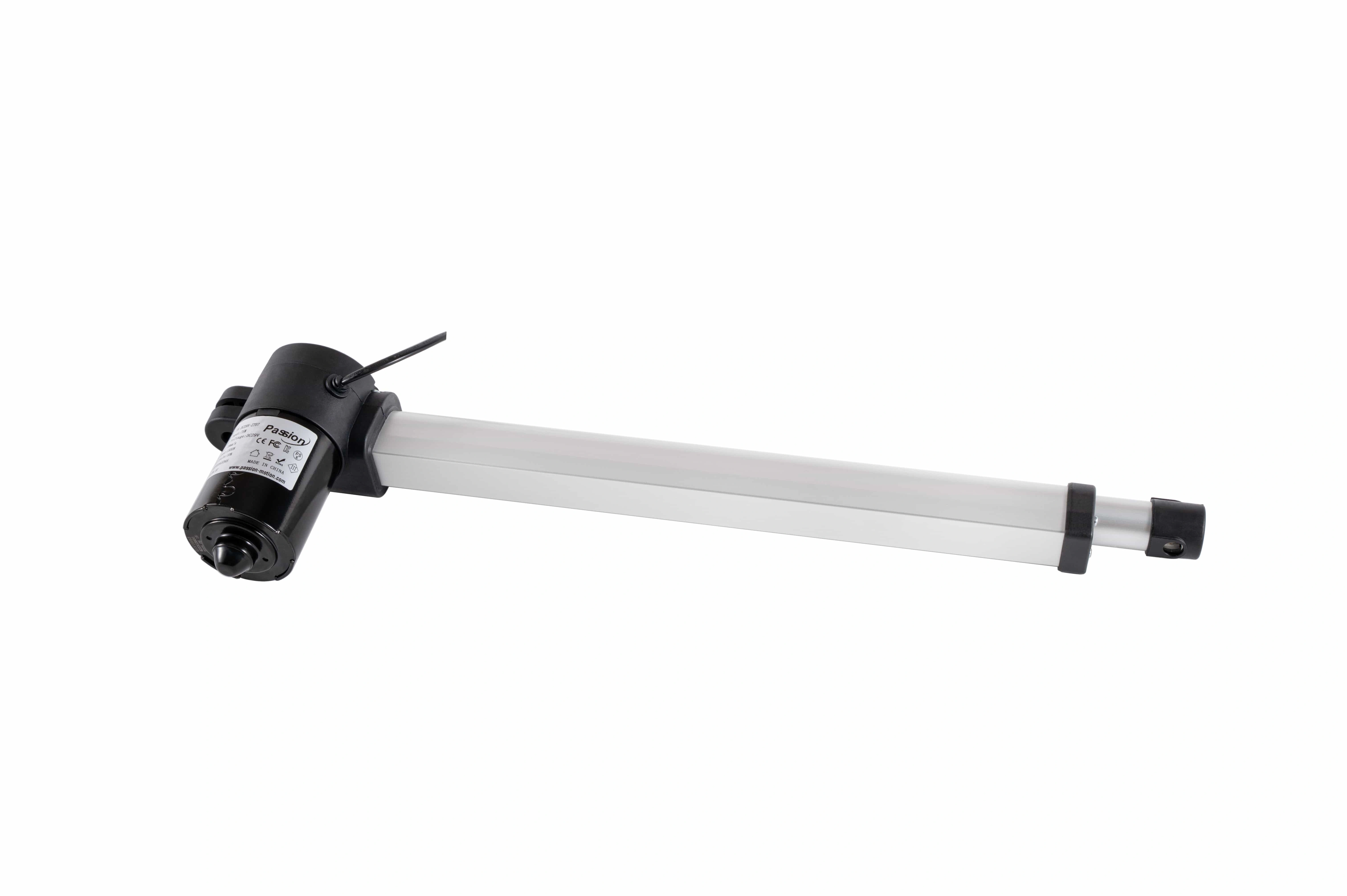
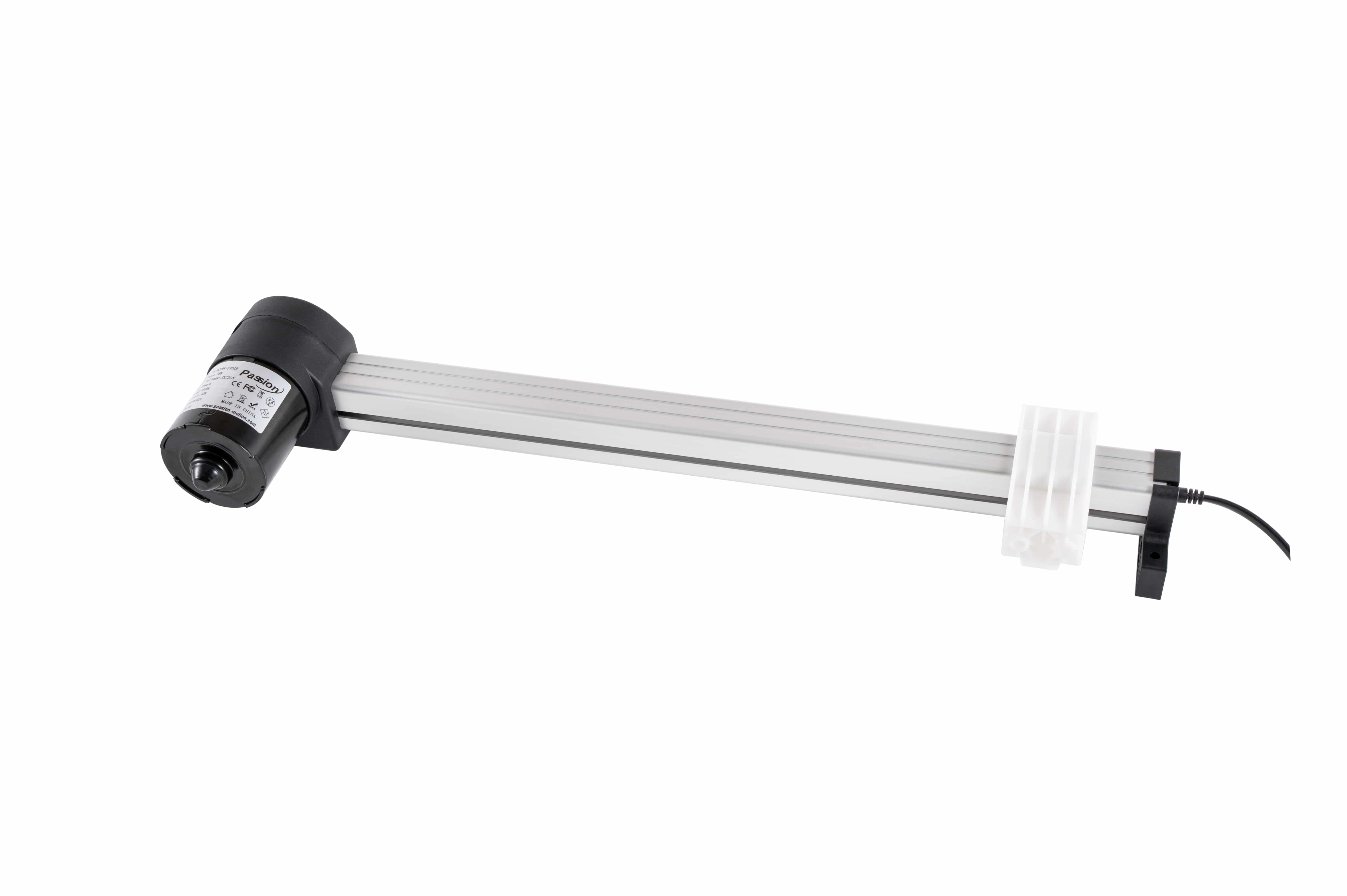
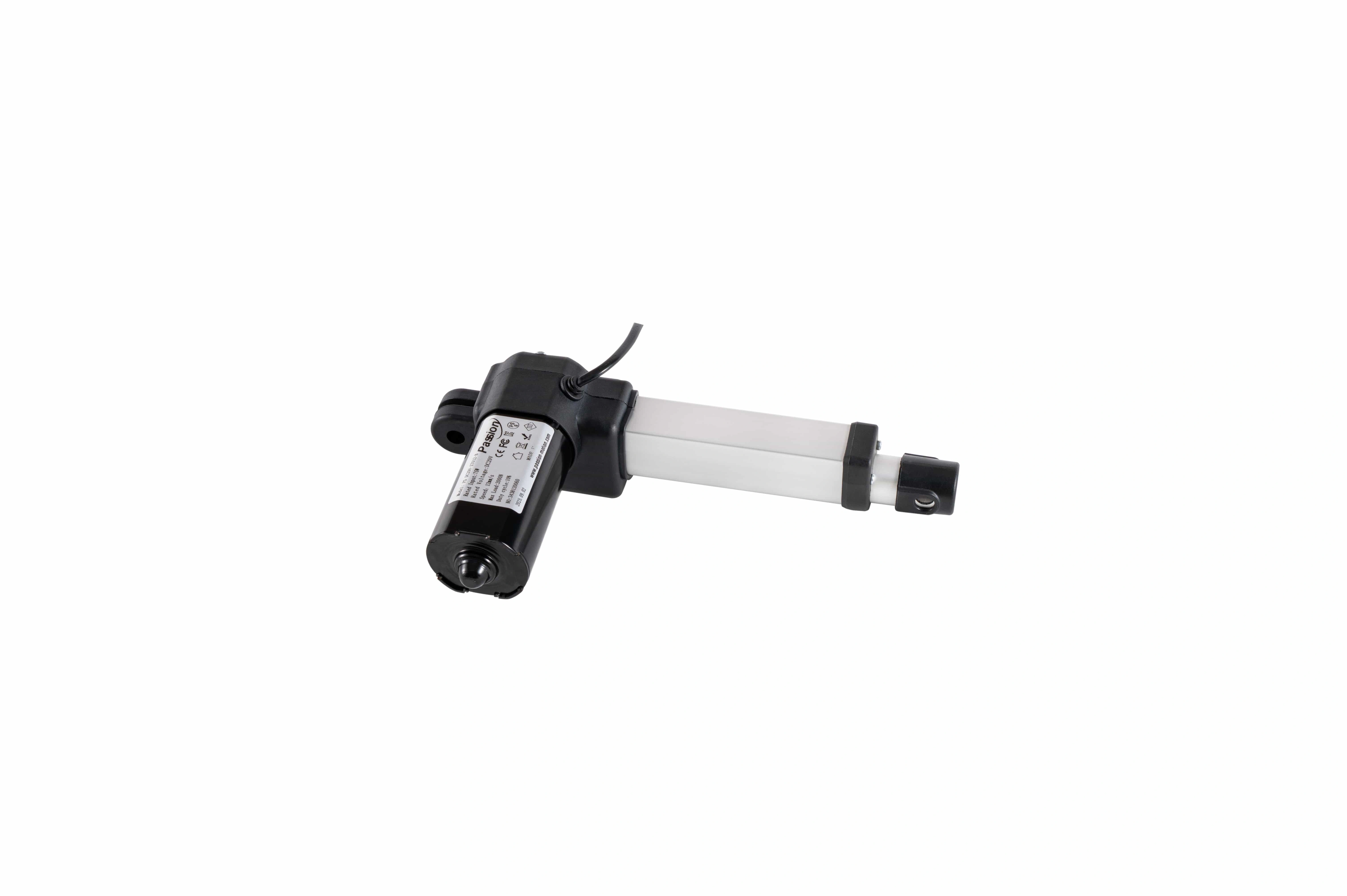
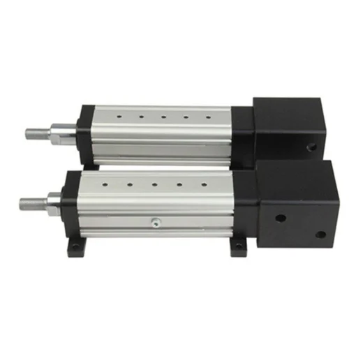
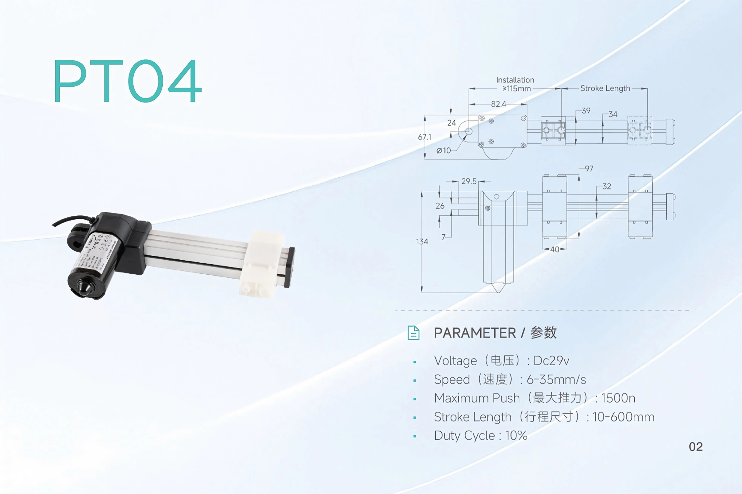 PT04 / flat-push layout
PT04 Linear Actuator
A low-profile DC 29V push unit for mechanisms that need a compact installation arrangement and configurable travel. Treat force, speed, stroke and duty as a published selection envelope—not one guaranteed operating point.
Change the engineering question before reading the table.
Force, speed and stroke are independent published limits. Use the selector to focus the decision you are checking; the page does not imply that all maxima occur together.
Start from the working load
The local record lists 1,500 N maximum push. Treat it as a ceiling for screening, then submit the real working load and mechanism geometry for configuration review.
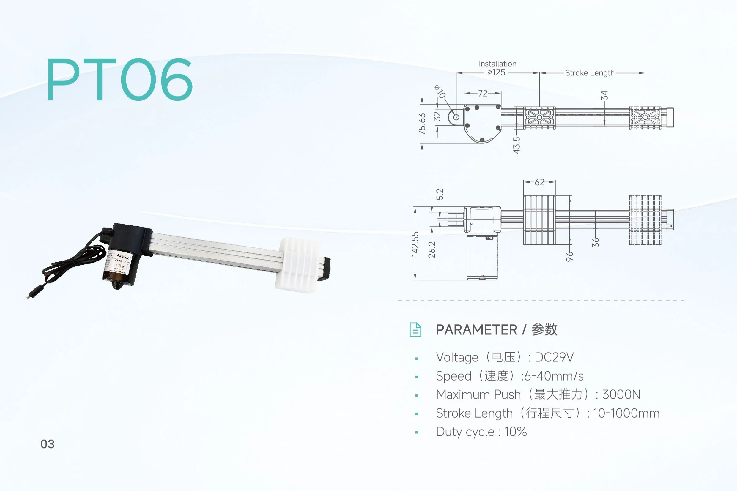
| Parameter | Published PT04 value | Selection note |
|---|---|---|
| Model | PT04 | Confirm exact model on the project request |
| Input voltage | DC 29V | Confirm the complete power architecture |
| Maximum push force | 1,500 N | Do not assume it coincides with maximum speed |
| Speed | 6–35 mm/s | Loaded-speed confirmation is required |
| Stroke | 10–600 mm | Select travel from the actual mechanism requirement |
| Duty cycle | 10% | Local record does not state the test basis |
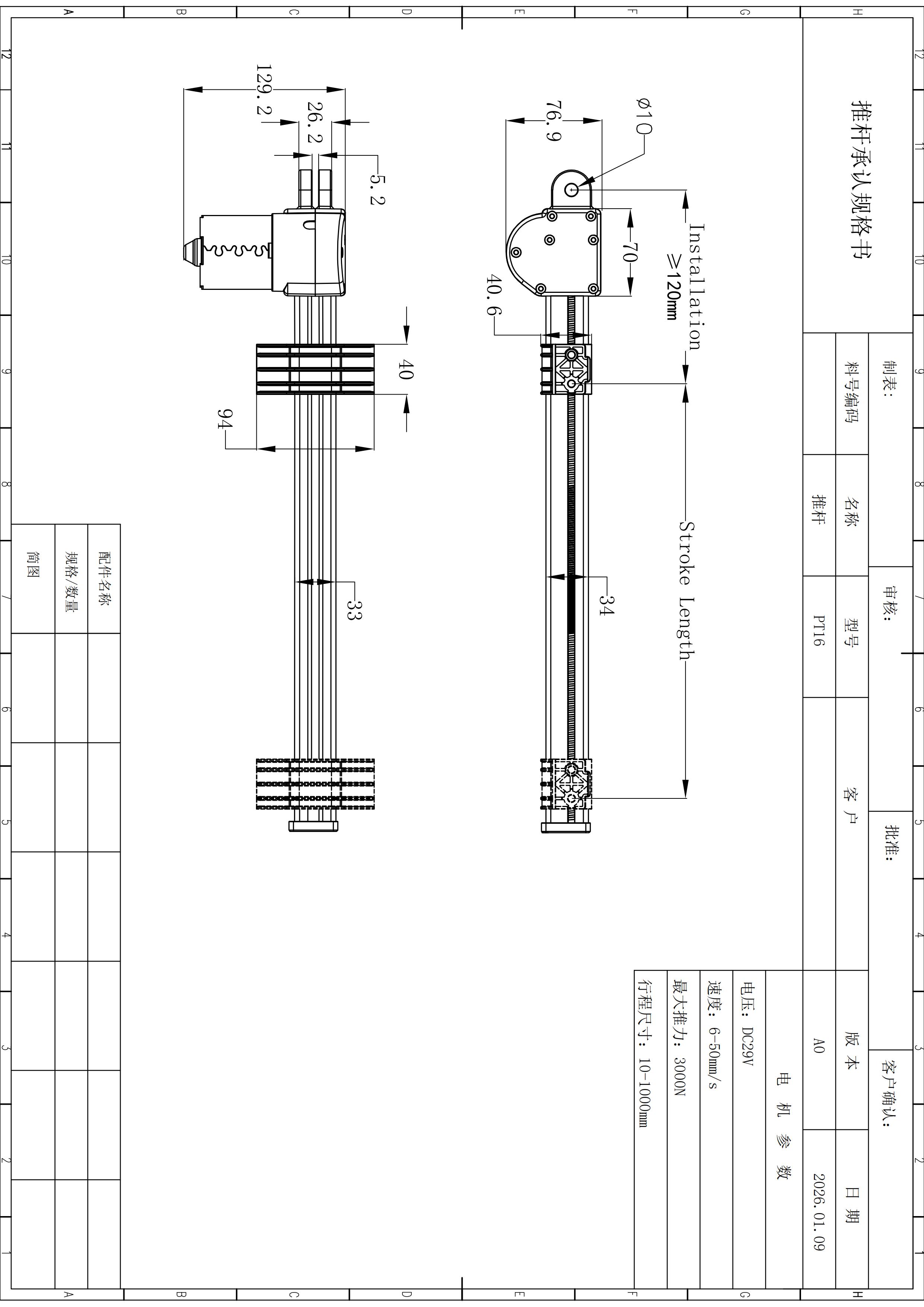
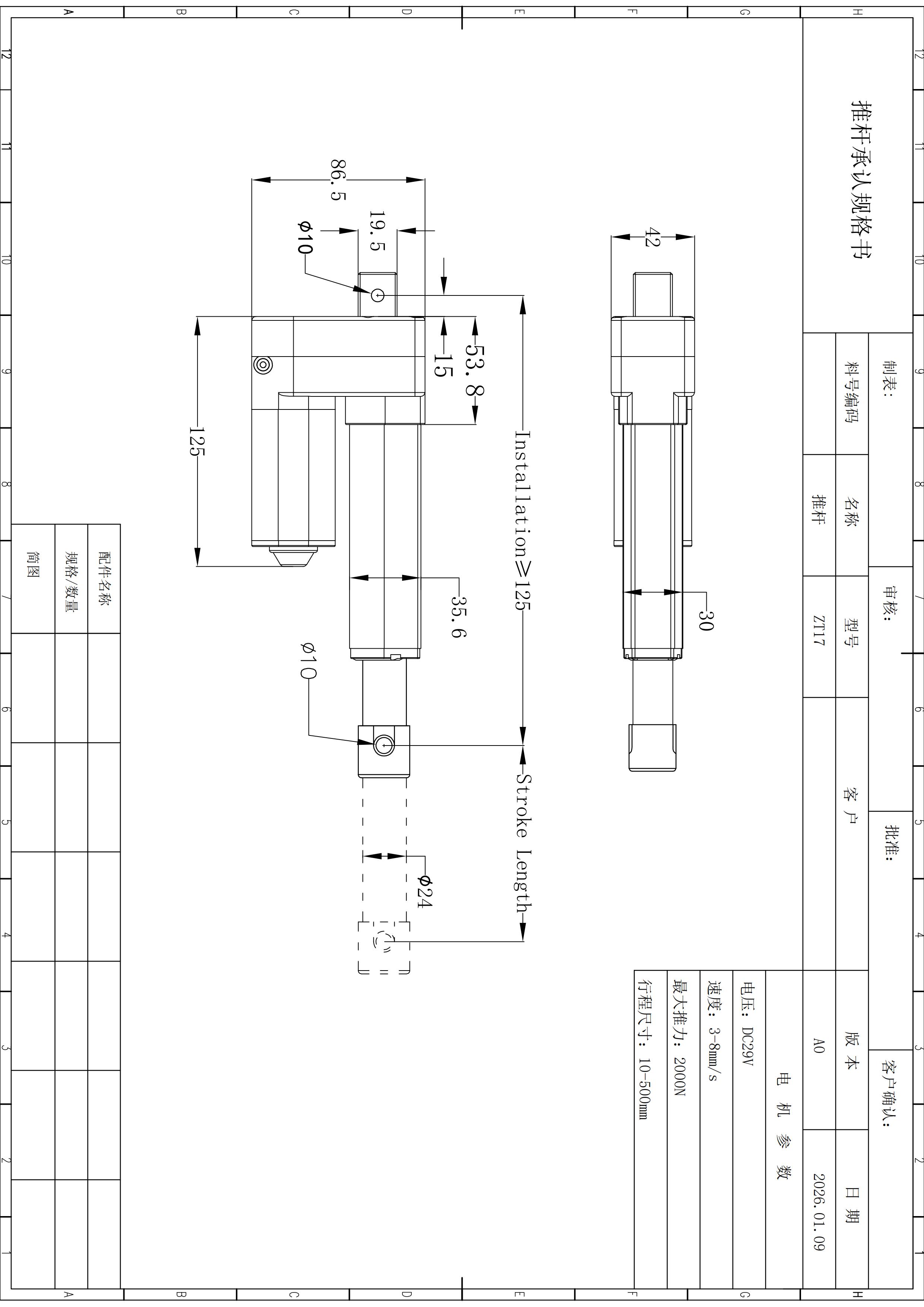
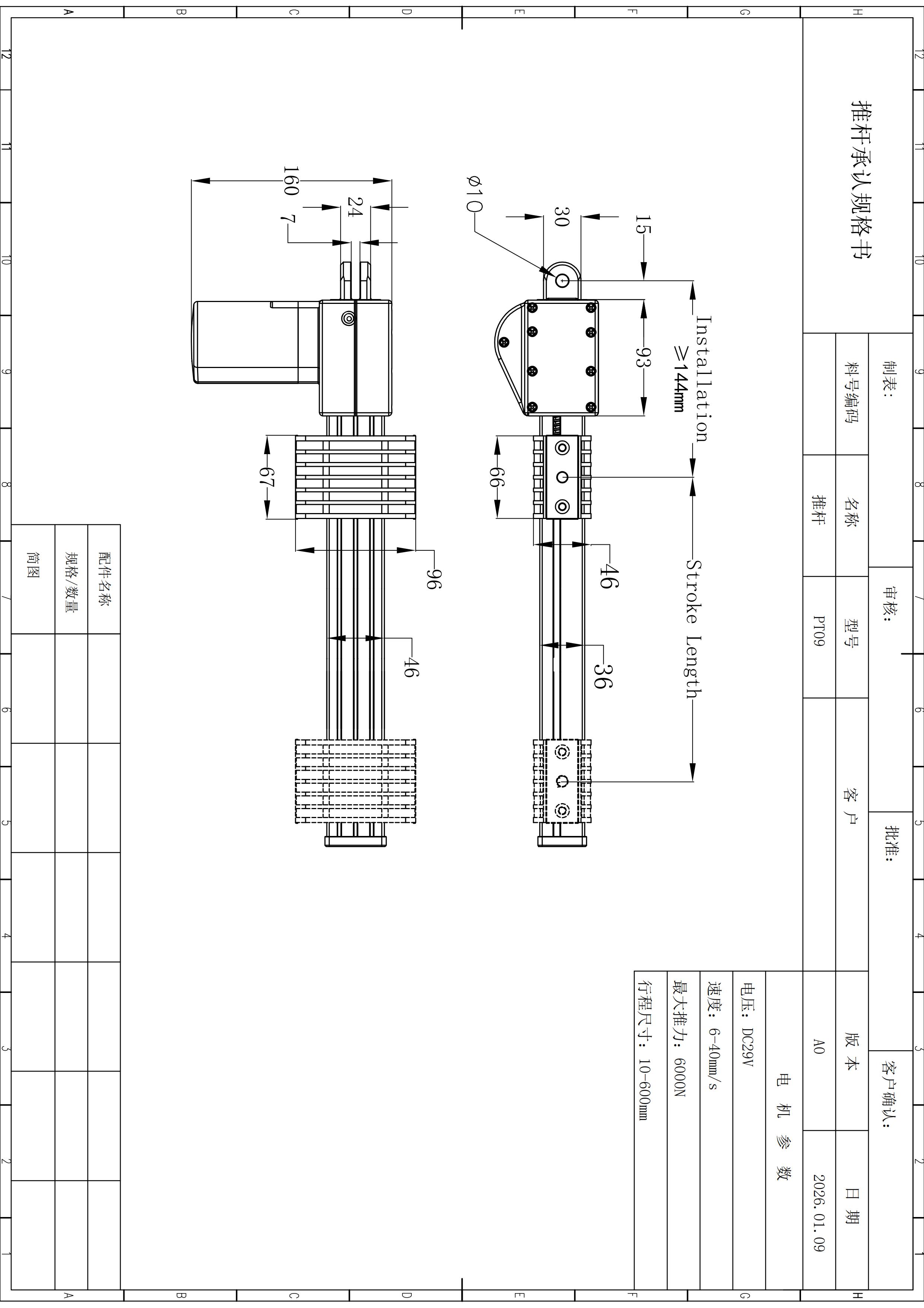
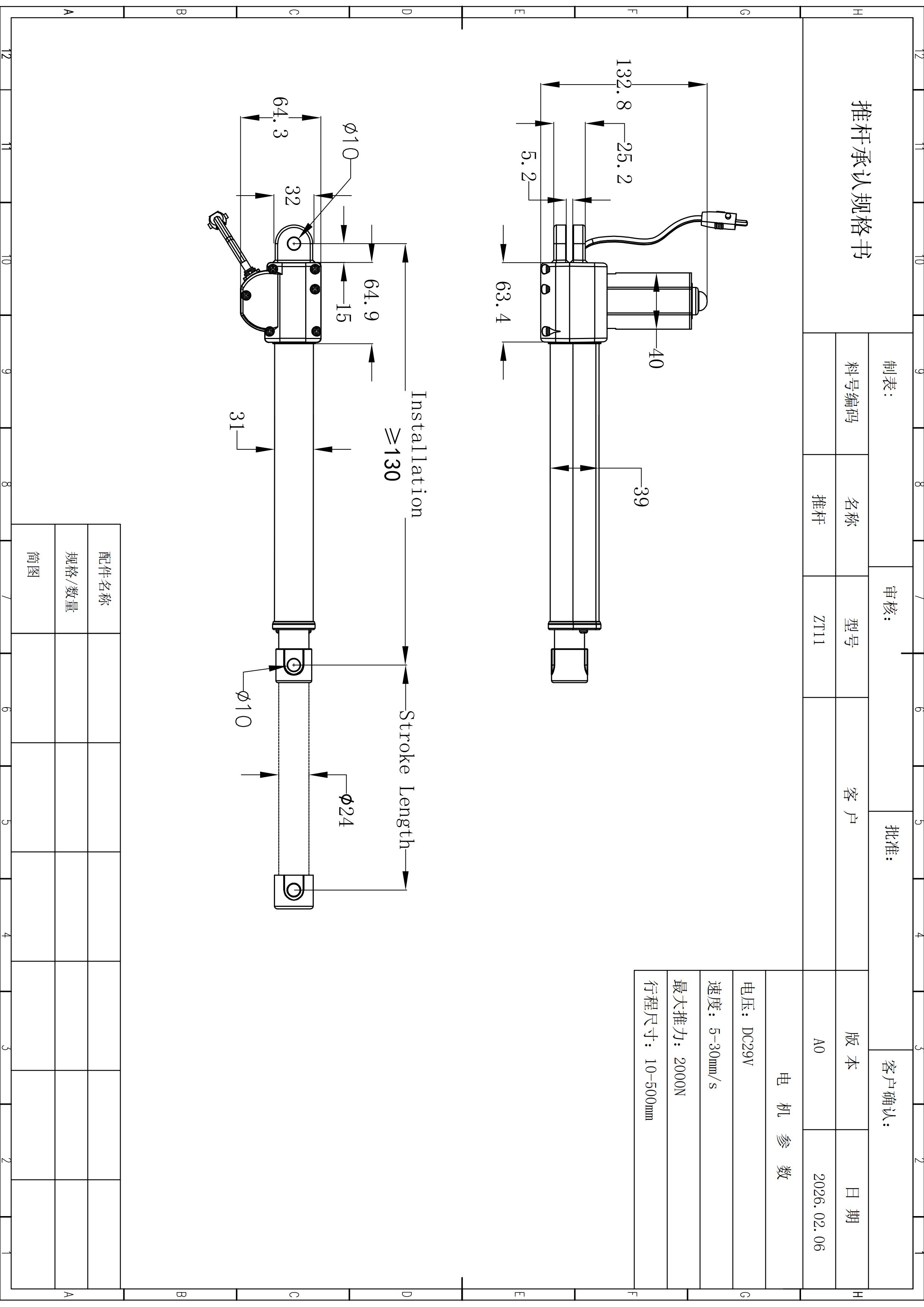
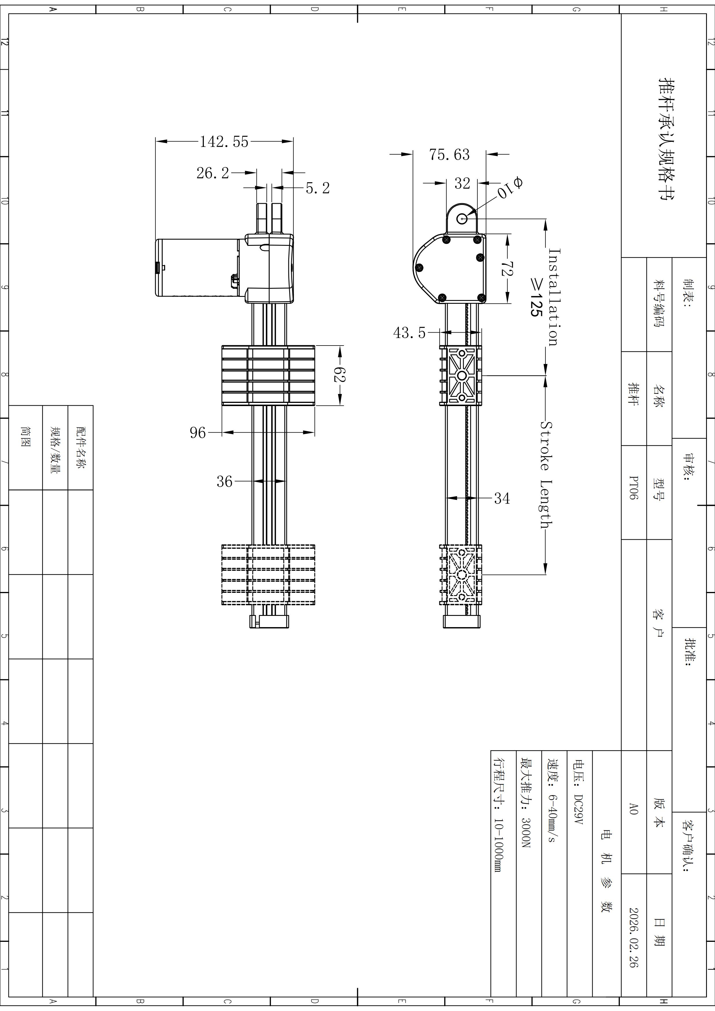
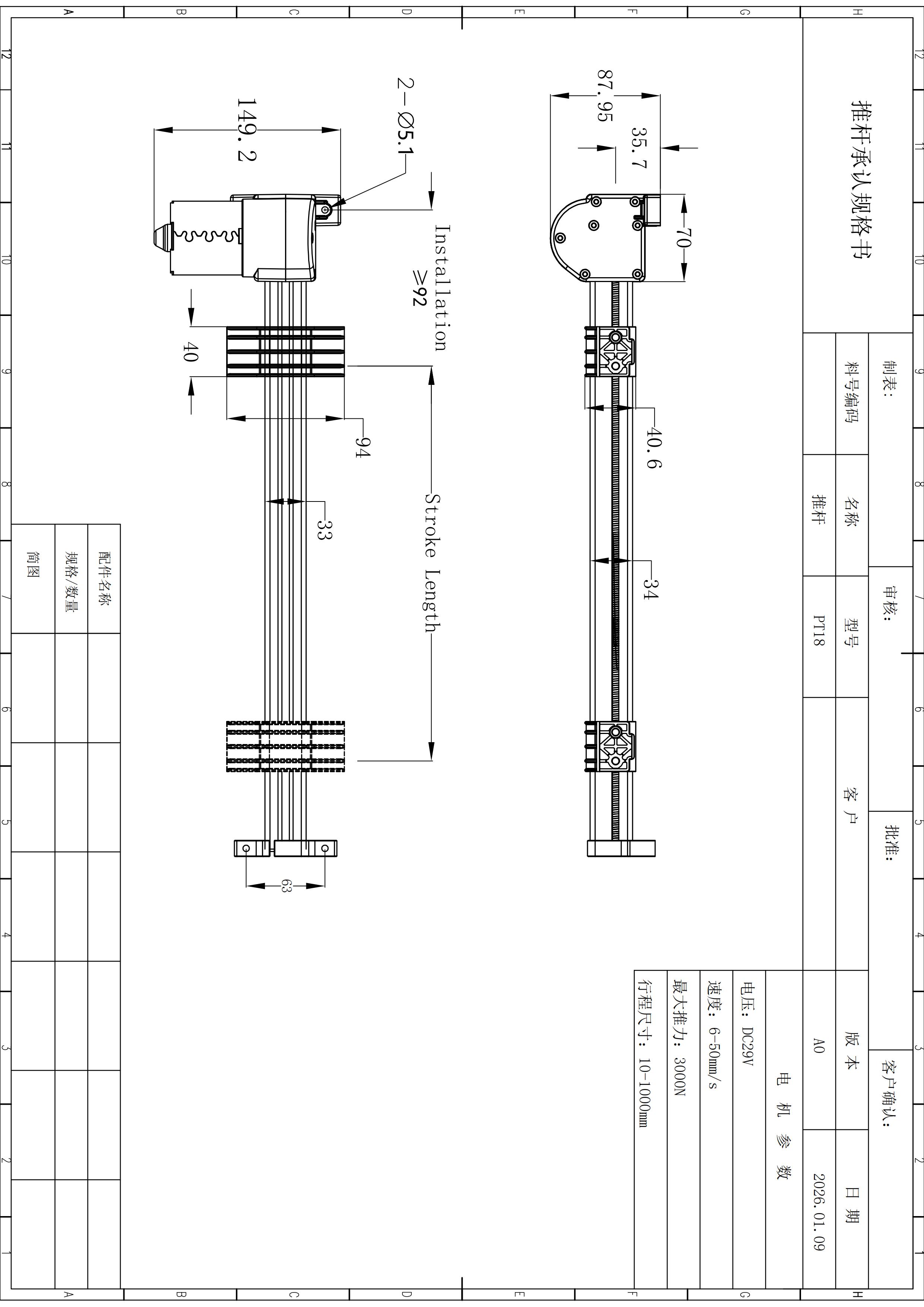
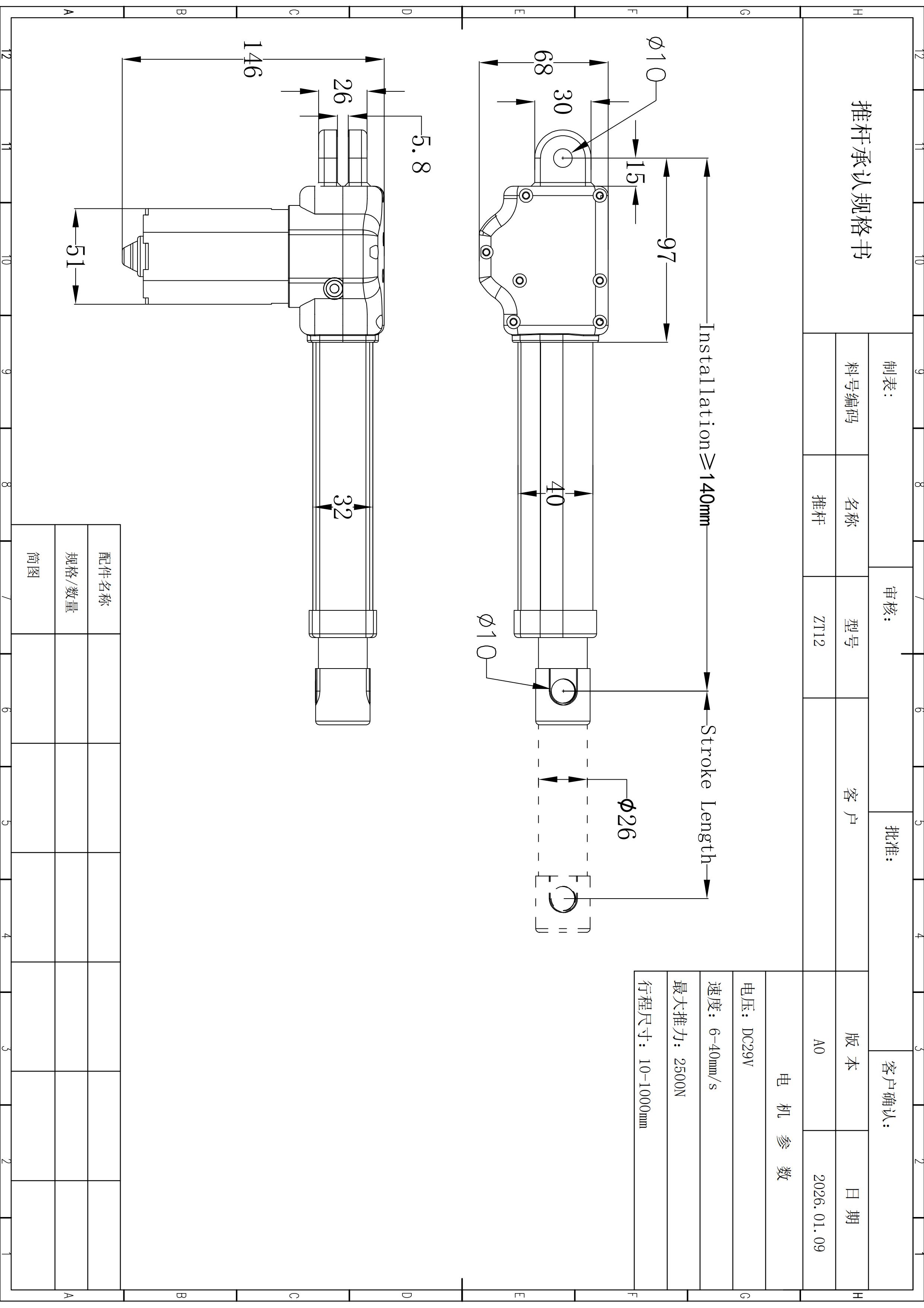
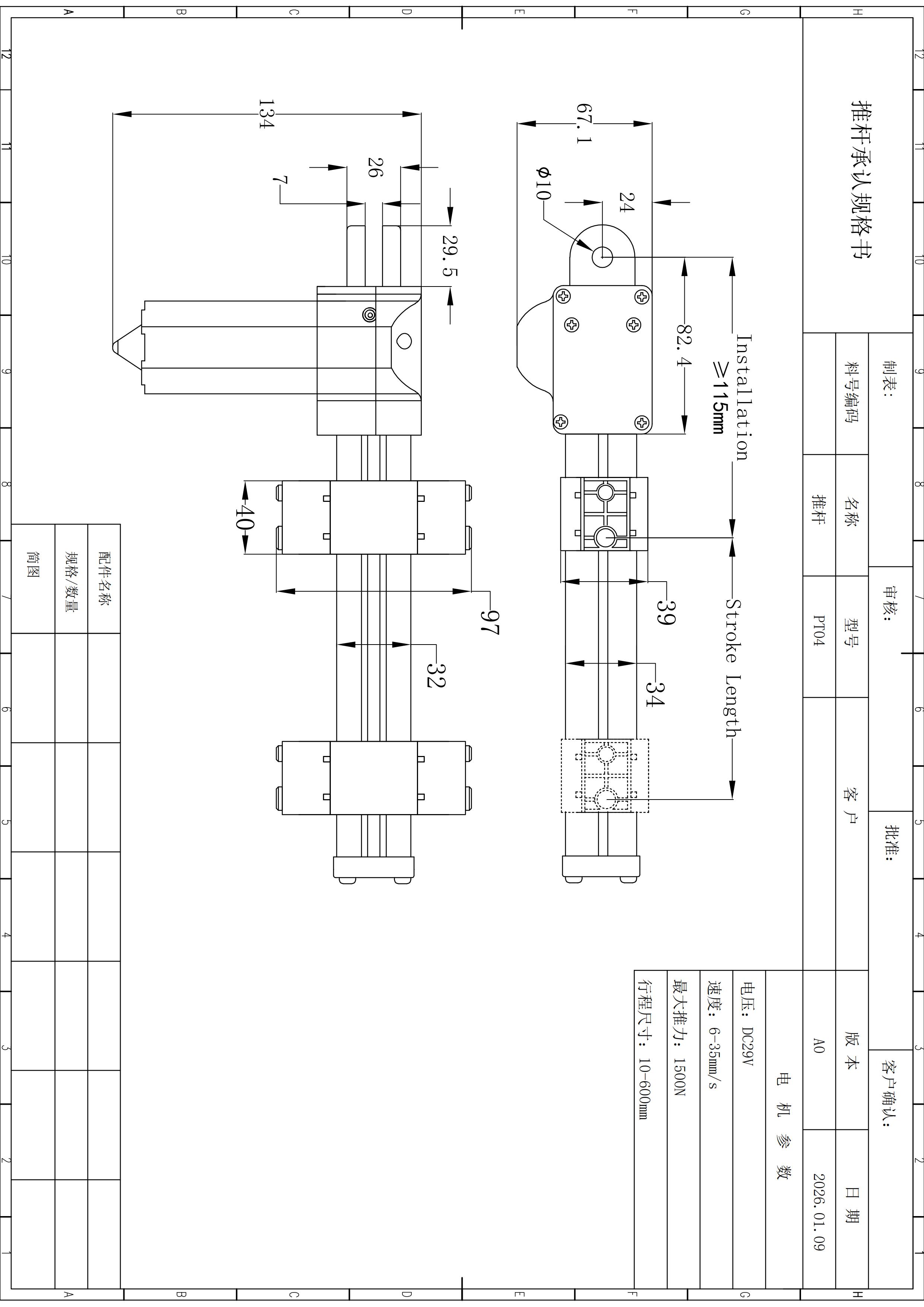
Check the compact envelope before machining surrounding structure.
The current dimensions are useful for early layout work, but they are not a released toleranced drawing.
Mechanical and electrical requirements should arrive together.
A configuration review becomes faster when the inquiry carries the operating point, geometry, controls and release evidence in one package.
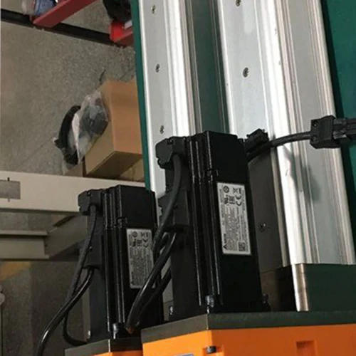
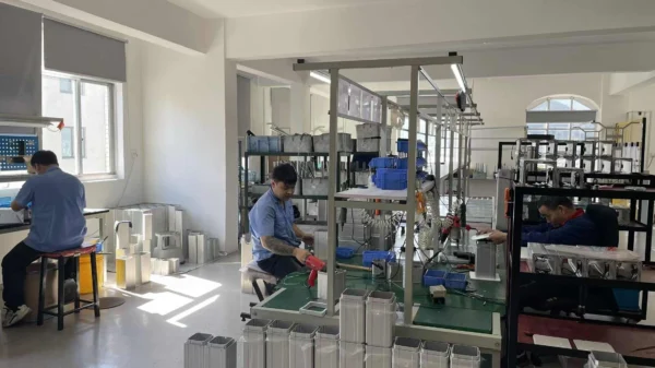
Inspect the production environment without turning imagery into unsupported claims.
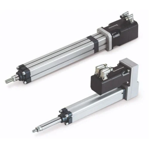
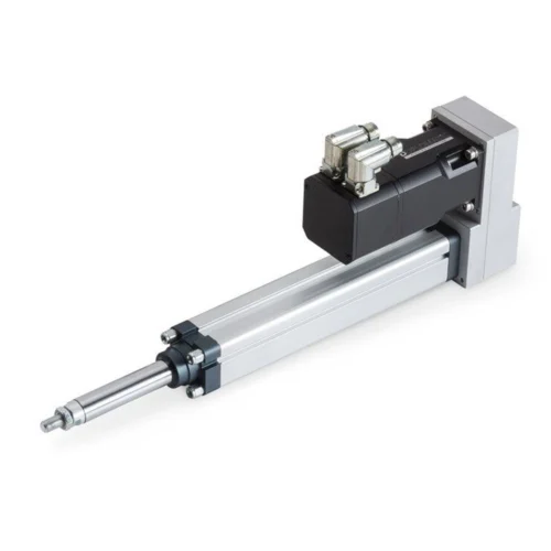
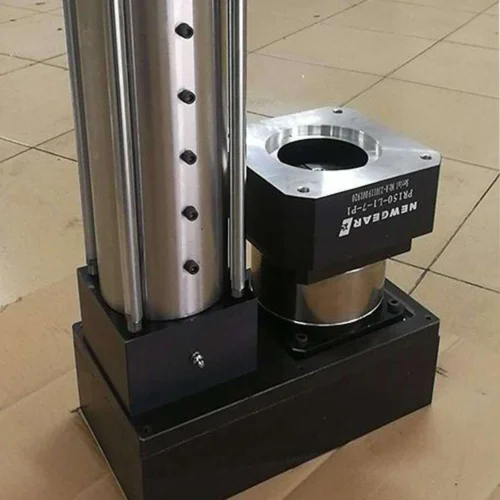
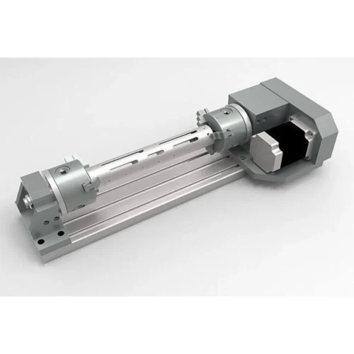
This first-party factory image is included as manufacturing context. It shows a ServoCylMotion assembly environment; it does not by itself prove that the photographed station is a PT04-specific process step or establish a quality/certification claim.
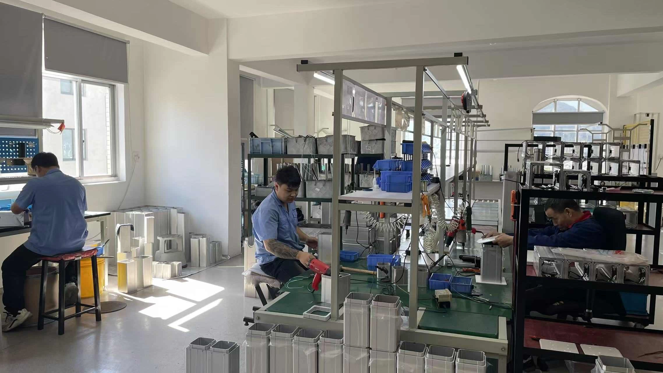 Assembly environment / first-party factory image
PT04 makes sense when the packaging problem is as important as the motion number.
PT04 is a candidate when the mechanism can use DC 29V, needs push force within the 1,500 N published maximum, requires 10–600 mm stroke and benefits from the compact flat-push arrangement.
Keep the published limits separate from verified operating points.
The model page supports early screening. Configuration-level data still governs release.
What is the maximum push force of PT04?
The local PT04 record lists 1,500 N maximum push. This does not prove every listed speed or stroke is available at that load.
What speed range is listed?
6–35 mm/s. Provide the working load if the design depends on a specific loaded speed.
What stroke range is available?
10–600 mm. Check the selected stroke against installation space and full-travel clearance.
What voltage does PT04 use?
PT04 is listed as DC 29V. The complete power and switching arrangement still requires review.
What does the 10% duty cycle mean?
The local record states 10% but does not provide the test basis or exact run/rest timing. Request clarification when cycle timing is critical.
Can 1,500 N and 35 mm/s be assumed at the same time?
No. This page does not contain a force-speed curve proving that operating point.
Are the listed dimensions ready for machining brackets?
No. They are preliminary references. Confirm the current released drawing before fixing tolerances or machining geometry.
Is a specific feedback or controller interface included?
The evidence package used for this page does not define one. State the required interface in the inquiry.
Review the mechanism—not only the headline values.
Send working load, loaded speed, stroke, installation space, cycle, environment, control and feedback needs, quantity and required documents.
Request PT04 review →