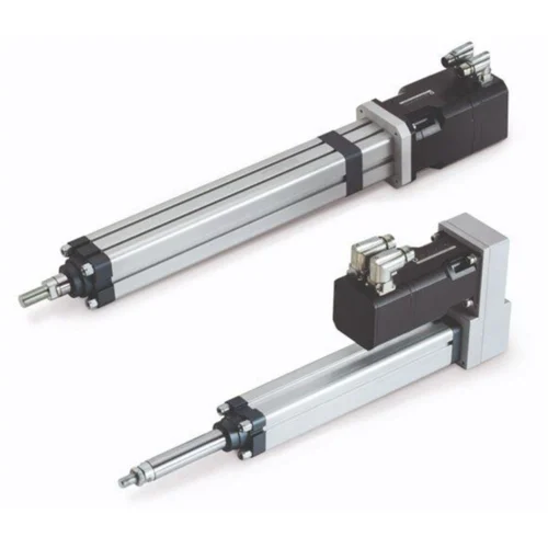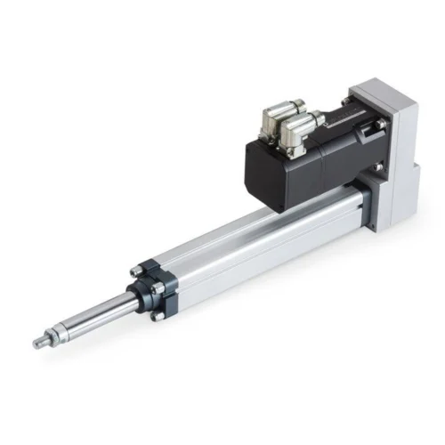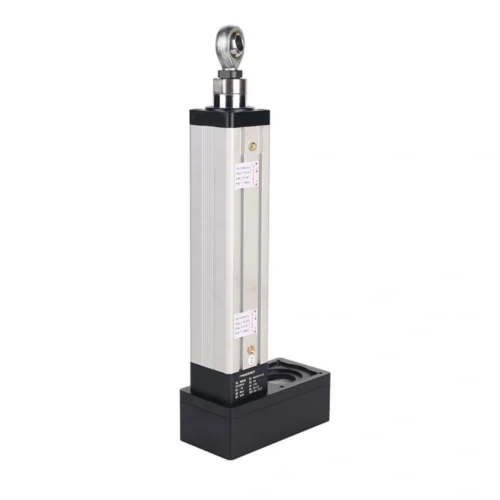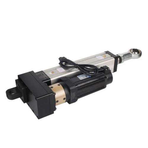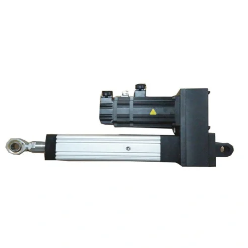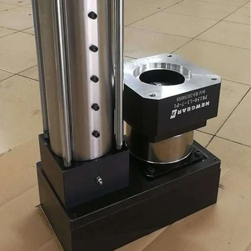
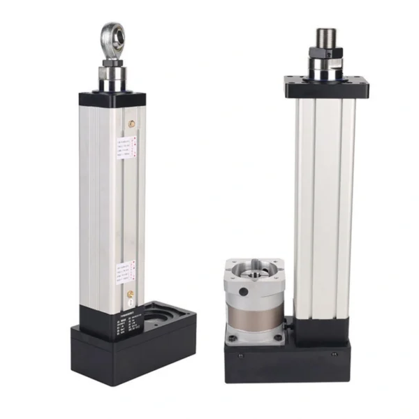

DG134 80 kN Servo Electric Cylinder
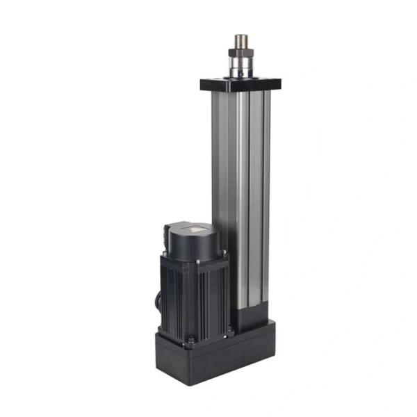
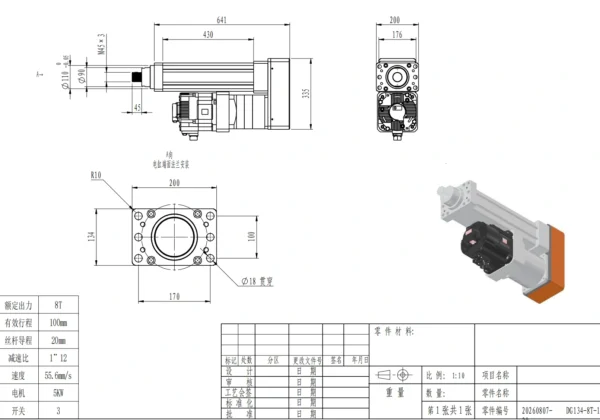
Review DG134-8T-100-20 specifications: 80 kN thrust, 100 mm stroke, 55.6 mm/s, 20 mm lead, 1:12 reduction, 5 kW servo motor and front-flange geometry.
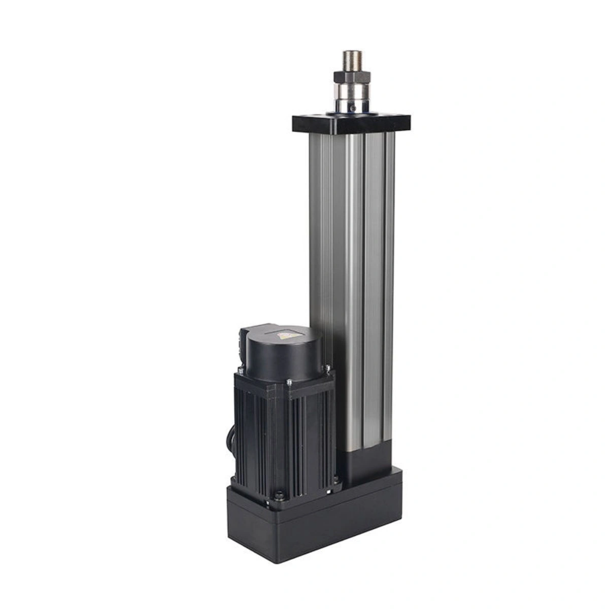
High force in a compact 100 mm motion envelope.
DG134-8T-100-20The documented DG134 configuration combines 80 kN rated thrust , 100 mm stroke and a published 55.6 mm/s speed with a 20 mm lead, 1:12 reduction and 5 kW servo motor. Treat these as configuration data for engineering review, not proof of every possible force-speed-duty combination.
Start from the real load path.
Confirm working force, direction, peak load, holding requirement and side-load control before releasing the mechanism.
Keep the complete DG134 configuration visible while you review the operating point.
These values describe the local DG134-8T-100-20 record. Final release should reconcile load, speed, stroke, duty, mounting, control, environment and current project drawings.
| Parameter | DG134-8T-100-20 value / engineering note |
|---|---|
| Rated thrust | 80 kN / 8T |
| Stroke | 100 mm |
| Published speed | 55.6 mm/s — confirm required speed under actual working load. |
| Screw lead | 20 mm |
| Reduction ratio | 1:12 |
| Servo motor | 5 kW |
| Position switches | 3 switches |
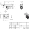
| Retracted overall length | 641 mm |
| Body length | 430 mm |
| Overall height | 335 mm |
| Rear width / pitch | 200 mm / 176 mm |
| Piston rod | Ø90 mm |
| Rod-end thread | M45 × 3 |
| Rod-end extension | 45 mm |
| Front pilot | Ø110 mm, tolerance 0 / −0.05 |
| Mounting type | Type A, front flange |
| Flange envelope | 200 × 134 mm |
| Corner radius | R10 |
| Hole spacing | 170 × 100 mm |
| Mounting holes | 4 × Ø18 mm |
The 80 kN number matters only if the surrounding structure can carry the load cleanly.
Reserve the retracted and extended envelope, confirm front-flange alignment, keep external guides responsible for side loads, and check all high-load interfaces against the current project drawing.
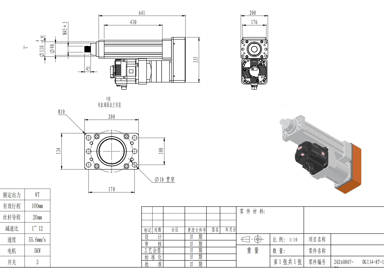
Control side load and alignment outside the cylinder.
The cylinder should be treated as an axial-force device. External guides, bearings or machine structure should control lateral forces, rotation and moment loads. Misalignment at 80 kN can quickly dominate bearing, screw and mounting life.
Check flange flatness, bolt pattern, pilot engagement, rod-end geometry, full-stroke clearance, cable routing, switch access, service access and hard-stop strategy before release.
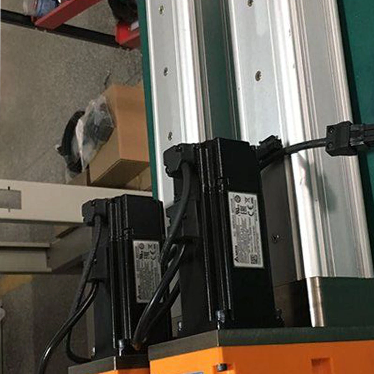
The mechanical ratio is known. The real duty point still needs engineering review.
Use the 20 mm lead, 1:12 reduction, 5 kW motor and 3-switch arrangement as integration inputs. Confirm the required controller, feedback strategy, power architecture, loaded speed and cycle profile for the project.
Do not infer continuous-duty capability, peak acceleration, holding behavior, servo tuning, force-speed curves or lifetime from the headline values alone. Those items depend on the selected operating point and system architecture.
Send the operating point and interfaces, not just “DG134”.
A complete RFQ reduces the risk of selecting around one headline number while missing the duty, mounting or control requirement.
| Input | What to provide |
|---|---|
| Force | Working load, peak load, direction, holding requirement and safety factor. |
| Travel | Required stroke plus retracted and extended mechanical envelope. |
| Loaded speed | Required speed at the actual working force. |
| Cycle | Extension/retraction time, dwell, cycles per hour and expected operating hours. |
| Mounting | Front-flange interface, alignment scheme, rod-end connection and external guidance. |
| Drive & controls | Controller, feedback, limit strategy, synchronization, communications and fault behavior. |
| Environment | Temperature, dust, moisture, contamination, washdown/corrosion needs where relevant. |
| Documentation | Required drawings, inspection/test records, acceptance criteria and project approvals. |
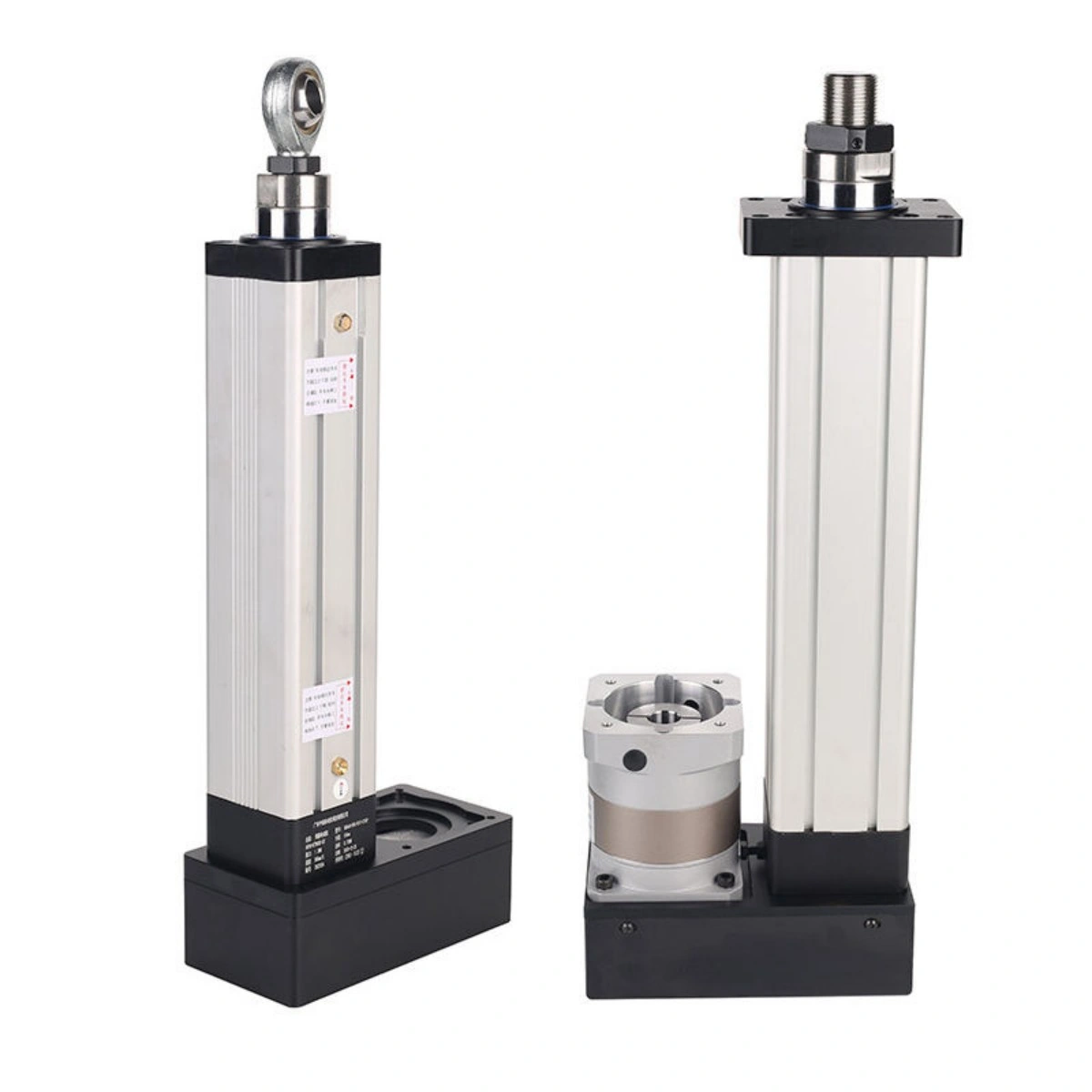
Best suited where axial force and controlled short travel matter more than a tiny package.
Potential fits include pressing, clamping, lifting/tilting, heavy fixture positioning, machine adjustment, industrial test equipment and custom automation where a servo-driven 80 kN / 100 mm motion envelope matches the real mechanism.
Application labels do not establish suitability. The actual load path, alignment, speed, duty, environment and control architecture still govern selection.
Freeze the operating point before the quotation becomes a release decision.
Confirm force, 100 mm travel, required loaded speed, cycle, 5 kW servo architecture, front-flange and rod-end interfaces, external guidance, switch/control logic, environment, quantity, drawings and acceptance evidence.
Use the documented values as boundaries, then verify the selected operating point.
DG134-8T-100-20 is a high-force 100 mm-stroke servo electric cylinder configuration with front-flange mounting.
What is the DG134 rated thrust?
The documented rated thrust is 80 kN / 8T.
What stroke and speed are documented?
The local configuration record lists 100 mm stroke and 55.6 mm/s published speed. Confirm the required speed under the actual load and cycle before release.
What drive configuration is listed?
The documented configuration uses a 20 mm lead, 1:12 reduction ratio and 5 kW servo motor.
How is DG134 mounted?
The recorded mounting type is Type A front flange, with a 200 × 134 mm flange envelope, 170 × 100 mm hole spacing, four Ø18 mm holes and a Ø110 pilot.
Can the cylinder carry side loads?
Design the machine so external guidance manages lateral forces and moments. High axial force does not make side loading harmless.
What should I include in a DG134 RFQ?
Send working and peak force, travel, required loaded speed, cycle, mounting geometry, guidance, drive/control needs, environment, quantity and required drawings or validation evidence.