
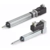
DG75 Servo Actuator | 7 kN, 100 mm, 100 mm/s
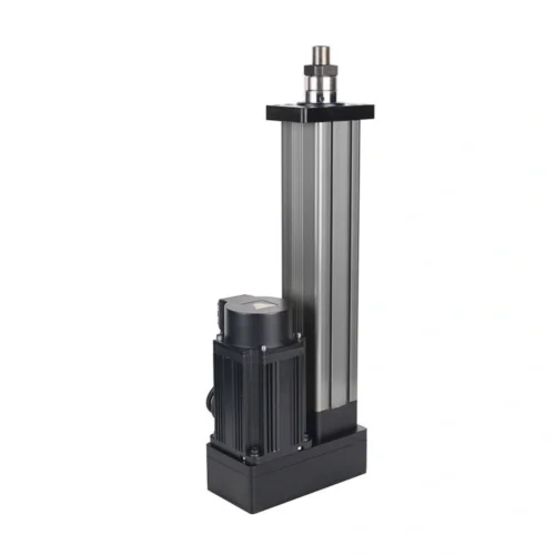
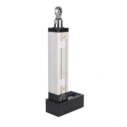
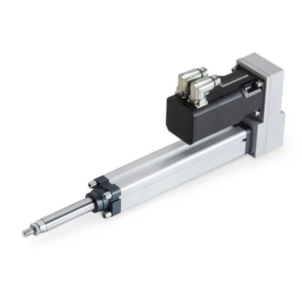
DG75-0.7T-100-5 with verified 7 kN rated thrust, 100 mm stroke, 100 mm/s speed, 5 mm lead, 1:2 reduction and 0.75 kW servo drive.
7 kN in a compact parallel-drive package.
DG75-0.7T-100-5DG75-0.7T-100-5 is documented for 7,000 N rated thrust , 100 mm stroke and 100 mm/s rated linear speed , with a 5 mm screw lead, 1:2 timing-belt reduction, 0.75 kW / 220 V AC servo motor and high-precision ball screw.
A 7 kN-at-100 mm/s continuous operating point is not established by the headline values alone. Cycle, dwell, acceleration, load direction and thermal conditions still need review.
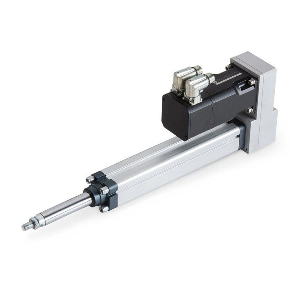
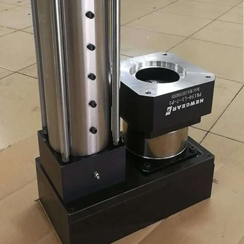
Follow the fold-back power path from servo input to linear output.
The interaction changes the engineering focus state and explanatory copy. It does not calculate torque, speed, duty or force capability beyond the documented configuration.
0.75 kW / 220 V AC servo input
The local record defines the motor power and supply class for this configuration. Controller model, feedback protocol, braking and command architecture remain project-integration items.
Keep the fixed motion and drivetrain data visible in one desktop table.
All values below belong to DG75-0.7T-100-5. They should not be extended into unsupported series-wide claims.
| Item | Documented value | Engineering note |
|---|---|---|
| Rated thrust / load | 7,000 N | Exact local product-record value. |
| Stroke | 100 mm | Exact configuration value. |
| Rated linear speed | 100 mm/s | Exact configuration value. |
| Screw lead | 5 mm | Exact configuration value. |
| Reduction ratio | 1:2 | Timing-belt drive. |
| Motor | 0.75 kW / 220 V AC servo | Exact configuration value. |
| Transmission | High-precision ball screw | Exact configuration value. |
| Position switches | 3 limit / proximity magnetic switches | Local record lists three switches. |
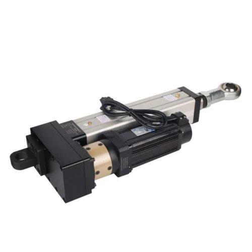
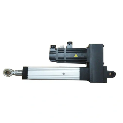
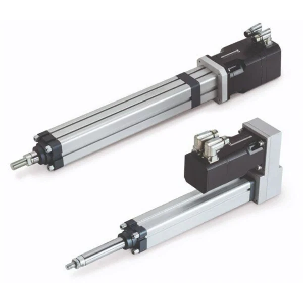
| Structure | Parallel fold-back motor mounting | Reduces axial package length. |
The fold-back motor helps axial packaging, but the whole interface still needs clearance.
Before bracket release, confirm drawing revision, alignment, rod-end connection, flange orientation, external guidance, fastener engagement and the full load path.
Strong fixed data does not remove the need for project-level operating confirmation.
The local record does not provide a force-speed curve, acceleration profile, duty-cycle test condition, thermal derating curve or continuous-cycle limit.
Known architecture
Confirm before release
Use the fold-back package as a starting point, then release the real operating point.
DG75 is worth evaluating when the project needs approximately a 7 kN thrust class, 100 mm travel, 100 mm/s rated motion and the documented package fits the machine.
Close the control, cycle and environment unknowns before release.
Send the real load, required loaded speed, cycle pattern, installation envelope, mounting preference, control requirements, environment, required documents, quantity and schedule for exact DG75 configuration review.
Configuration data first; system integration assumptions second.
The fold-back architecture is useful packaging information, but the current project record still requires controlled confirmation for operating and integration conditions.
Are 7 kN, 100 mm, and 100 mm/s documented for the same configuration?
Yes. The local product record assigns all three values to DG75-0.7T-100-5. The final force-at-speed requirement should still be checked against the actual load and cycle profile.
What motor and transmission are documented?
The configuration lists a 0.75 kW / 220 V AC servo motor, a high-precision ball screw, 5 mm lead, and 1:2 timing-belt reduction.
What is the retracted length?
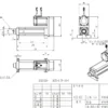
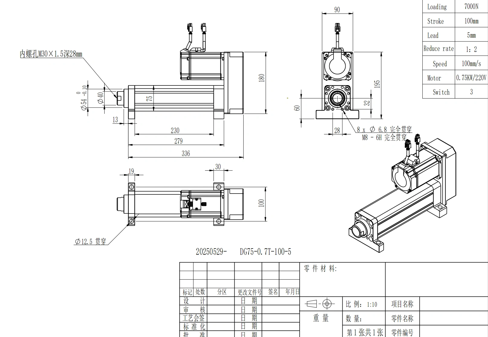
The documented overall retracted length is 336 mm. The record also contains 279 mm and 230 mm housing-related labels, which are preserved separately rather than converted into an inferred formula.
What mounting interfaces are listed?
The record includes foot mounting and front-flange options, a Ø40 mm rod, M30 × 1.5 rod-end thread, Ø54 mm front pilot, 8 × Ø6.8 mm front holes, M8-6H threaded holes, and 4 × Ø12.5 mm base holes.
Are positioning accuracy, repeatability, ingress rating, and duty cycle specified?
No numerical model-level values for those items are included in the current local record. Confirm them against controlled project documentation when they are acceptance requirements.
What should I send before release?
Send the real load, required loaded speed, cycle pattern, installation envelope, mounting preference, control requirements, environment, required documents, quantity and schedule through the contact page.