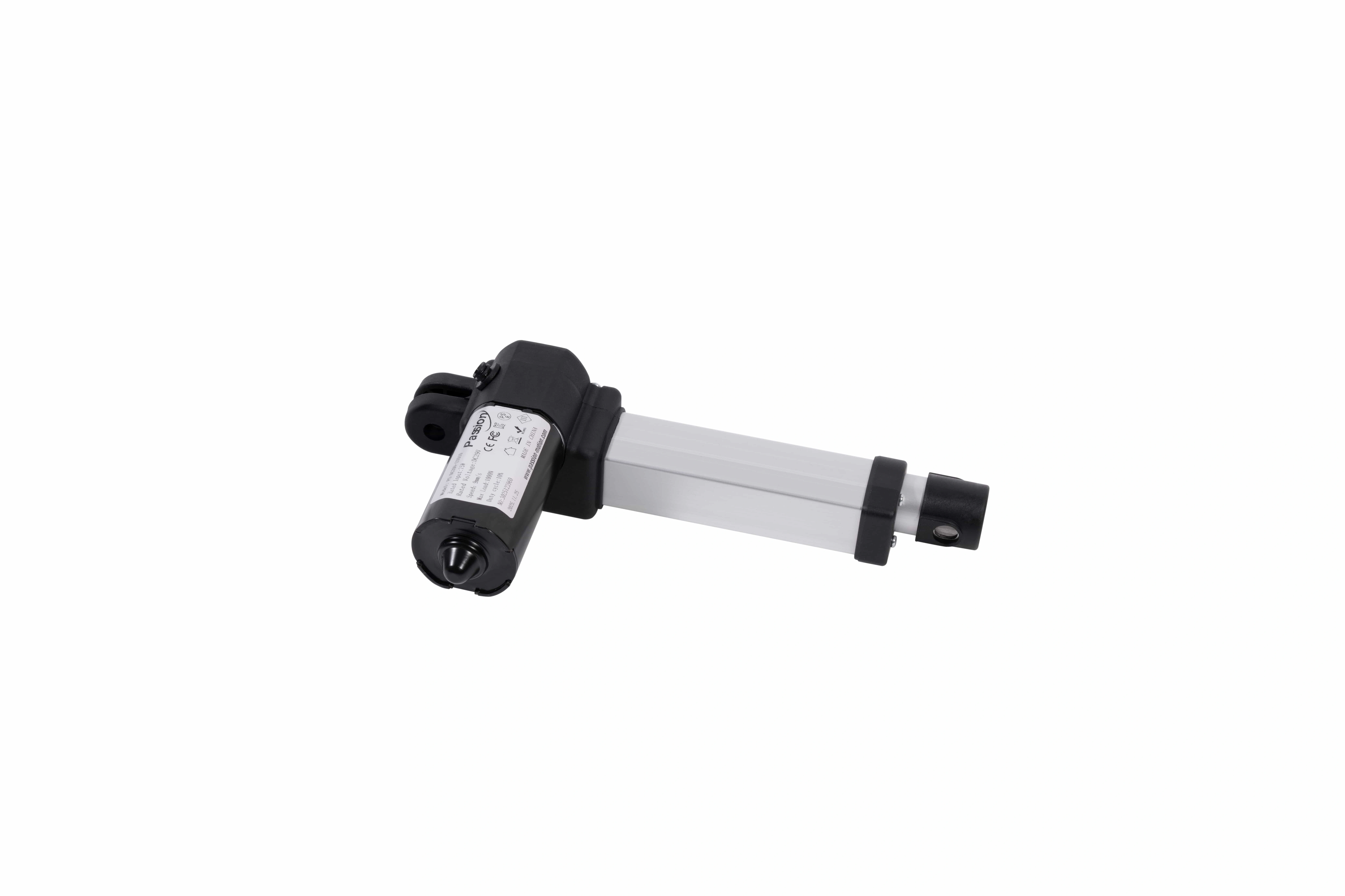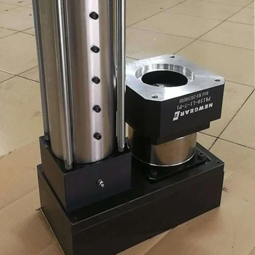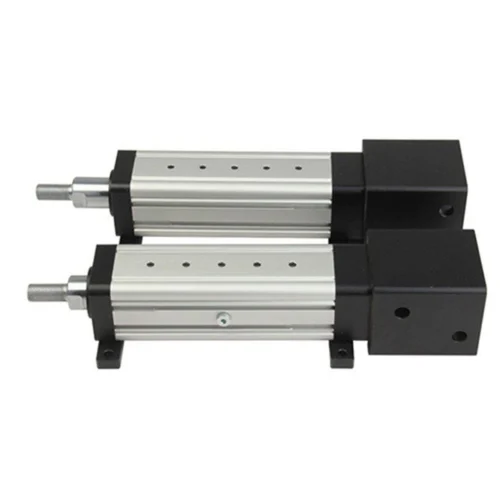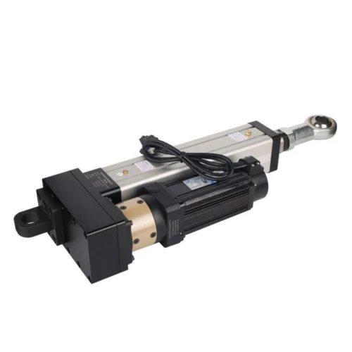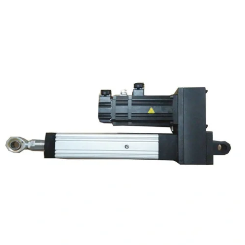

DG52 Actuator | 50 kg, 190 mm, 125 mm/s
DG52-50KG-190-5 with verified 50 kg rated output, 190 mm stroke, 125 mm/s speed, 0.4 kW motor, key dimensions, and project selection notes.
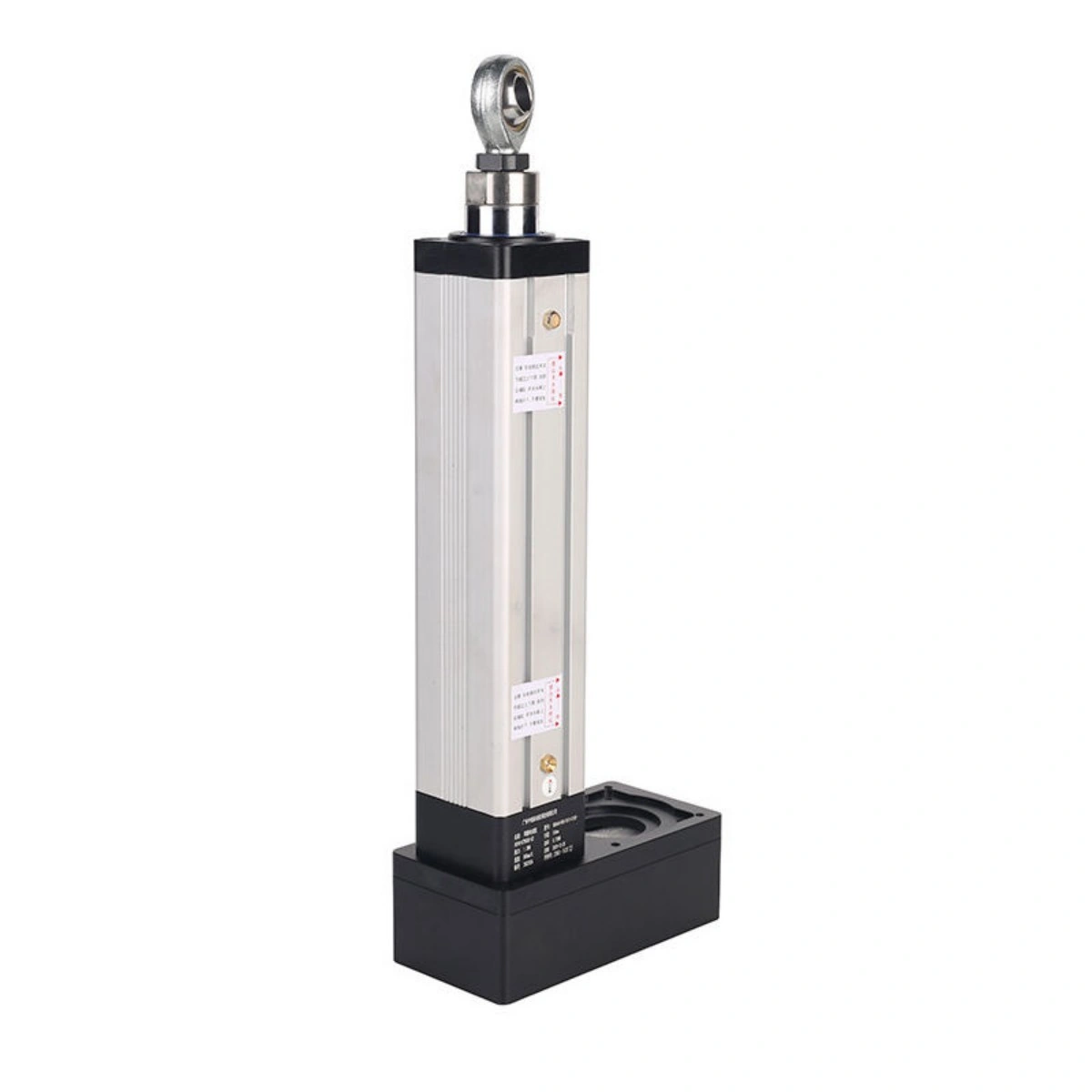
190 mm of travel with a documented 125 mm/s motion rate.
DG52-50KG-190-5DG52-50KG-190-5 is documented for a 50 kg rated output , 190 mm effective stroke and 125 mm/s travel speed , with a 5 mm screw lead, 1:1 reduction, 0.4 kW motor and three switches.
About 490 N is a transparent conversion from 50 kgf under standard gravity, not a separately published test rating. Loaded-speed, duty and thermal conditions still require project review.
See the 190 mm stroke without pretending it is a complete operating envelope.
The state control below changes the illustrated rod position only. It helps packaging review; it does not calculate force-at-speed, thermal behavior, acceleration or cycle capability.
Start from the retracted package.
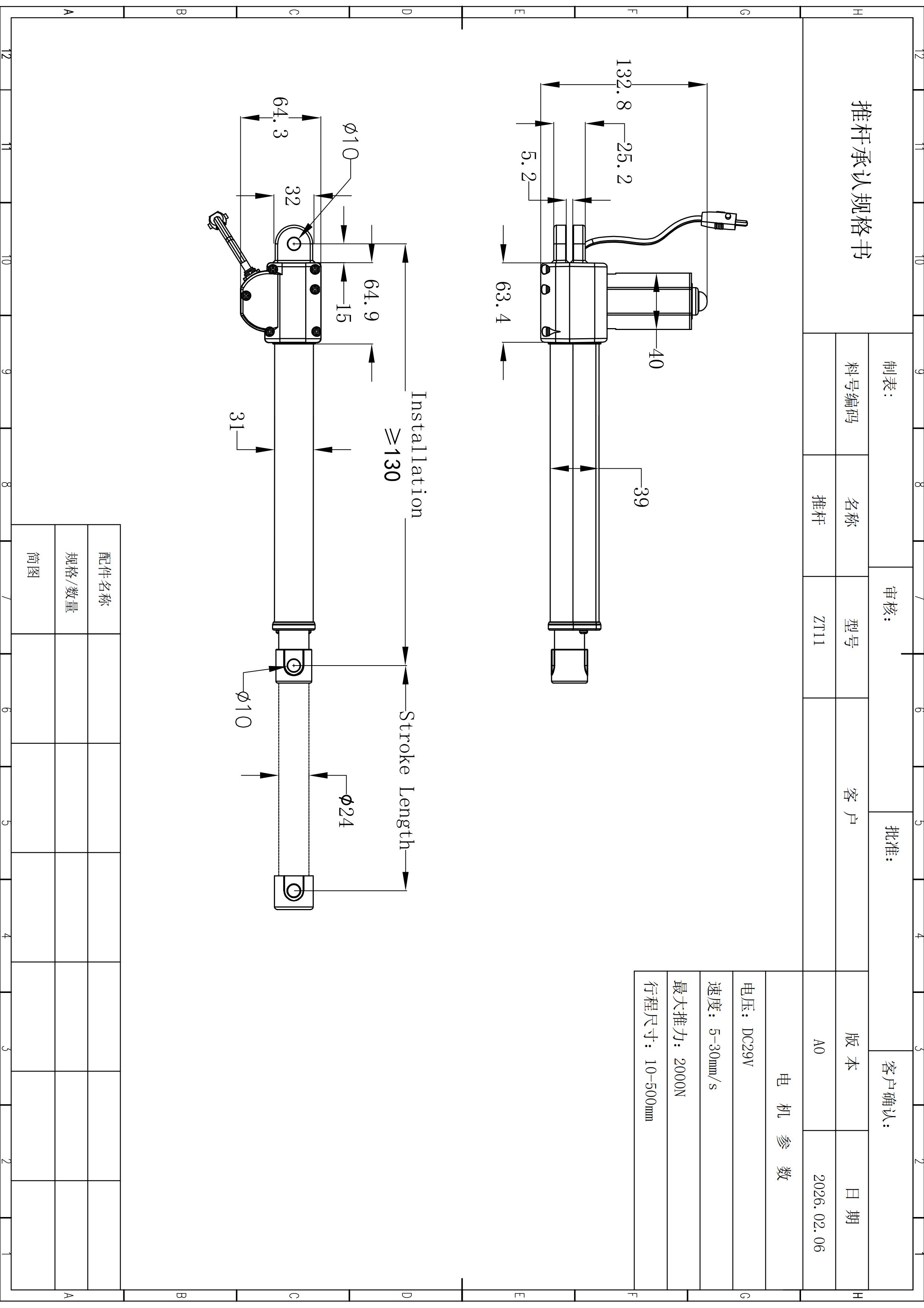
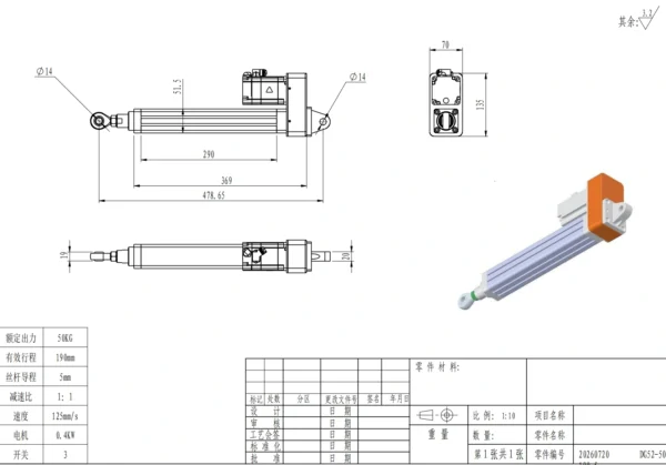
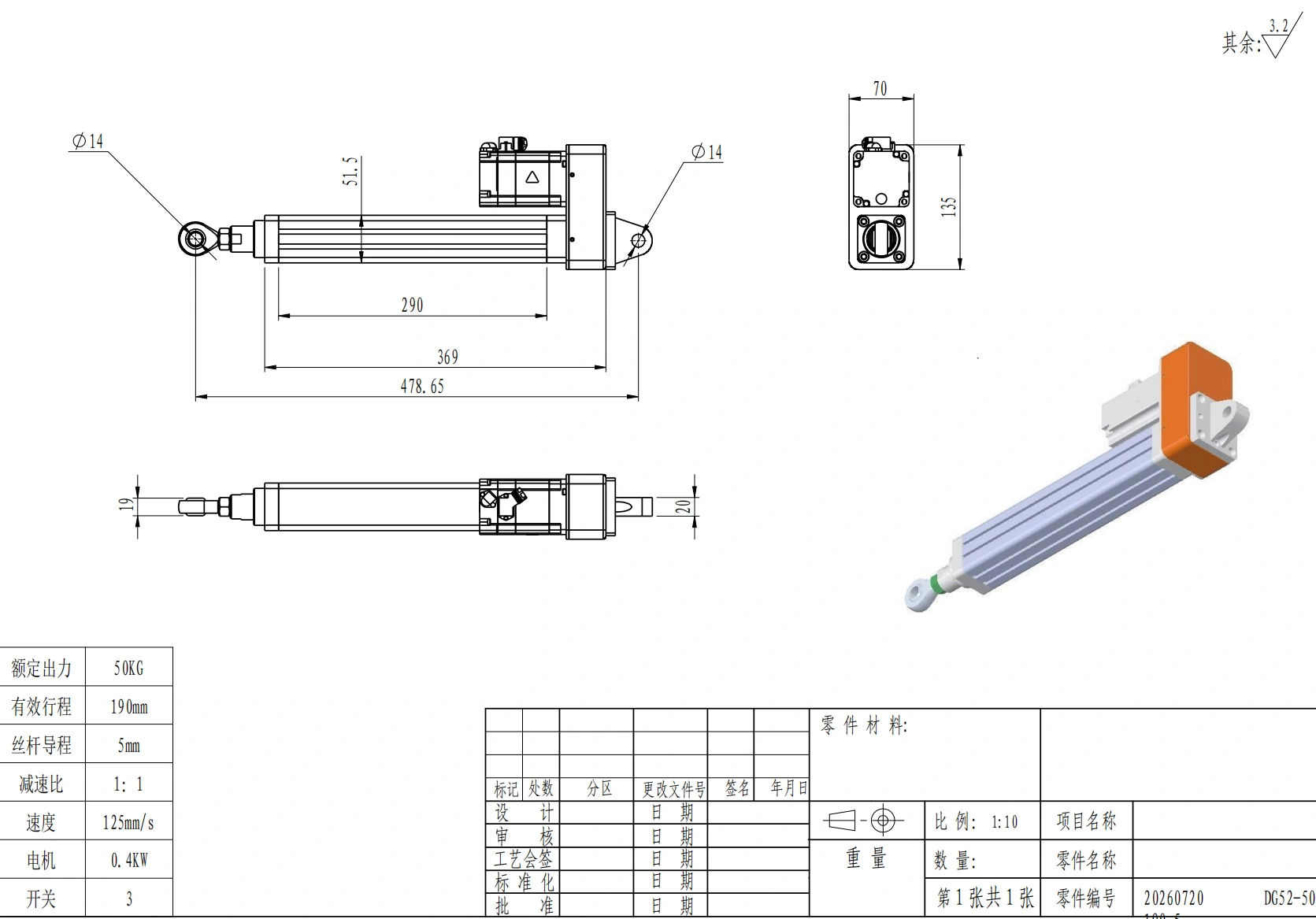
The drawing lists a 478.65 mm retracted center distance. Reserve bracket geometry, articulation and service clearance before adding working travel.
Keep the drawing facts separate from the conditions that still need release.
The page is configuration-specific. Missing operating conditions are intentionally left as review items rather than being filled with generic actuator assumptions.
Documented configuration
Confirm for the project
Review the fixed DG52 values in one flat desktop table.
These values describe DG52-50KG-190-5. They are not a series-wide envelope.
| Item | DG52-50KG-190-5 value | Engineering note |
|---|---|---|
| Rated output | 50 kg | Value shown on the drawing. |
| Approx. force equivalent | 490 N | Conversion from 50 kgf under standard gravity; not a separately printed rating. |
| Effective stroke | 190 mm | Exact drawing value. |
| Travel speed | 125 mm/s | Exact drawing value; loaded-speed conditions are not stated. |
| Screw lead | 5 mm | Exact drawing value. |
| Reduction ratio | 1:1 | Exact drawing value. |
| Motor power | 0.4 kW | Exact drawing value. |
| Switch count | 3 | Switch type and logic are not stated. |
Bracket release starts with the controlled drawing, not a guessed dimension chain.
The 290 mm and 369 mm figures remain separate drawing labels and are not combined into an inferred formula.
DG52 is useful when the geometry fits and the real operating point can be validated.
Do not select from the model code alone when side load, aggressive cycle demand, tight positioning, a defined force-at-speed point or a specific feedback protocol controls the project.
Separate a dimensional match from a verified operating-point match.
Send the working load, loaded speed, travel requirement, installation envelope, cycle pattern, mounting details, control needs, environment, documents required, quantity and target schedule for exact DG52 configuration review.
Drawing-backed facts, without unsupported performance assumptions.
Use the current controlled project documentation whenever a dimension, tolerance, environmental limit or operating condition becomes an acceptance criterion.
Is 490 N an original drawing value?
No. The drawing lists 50 kg rated output. About 490 N is the force equivalent of 50 kgf under standard gravity and is included only as a conversion.
Does 125 mm/s mean that speed is guaranteed at a 50 kg working load?
The drawing lists both values for this configuration but provides no load-speed curve or test conditions. A specified force-at-speed point should be confirmed for the project.
What stroke is documented?
The effective stroke is 190 mm.
What are the main mounting dimensions?
The drawing shows a 478.65 mm retracted center distance, 70 mm body width, 135 mm overall height, and Ø14 mm front and rear pin holes. It also contains 290 mm and 369 mm body-related labels.
Are position accuracy, repeatability, protection level, or cycle limit verified here?
No target values for those items appear in the available drawing record. Confirm them against controlled project documentation when they are part of acceptance criteria.
What should I send before release?
Send the working load, loaded speed, travel requirement, installation envelope, cycle pattern, mounting details, control needs, environment, documents required, and quantity through the contact page.