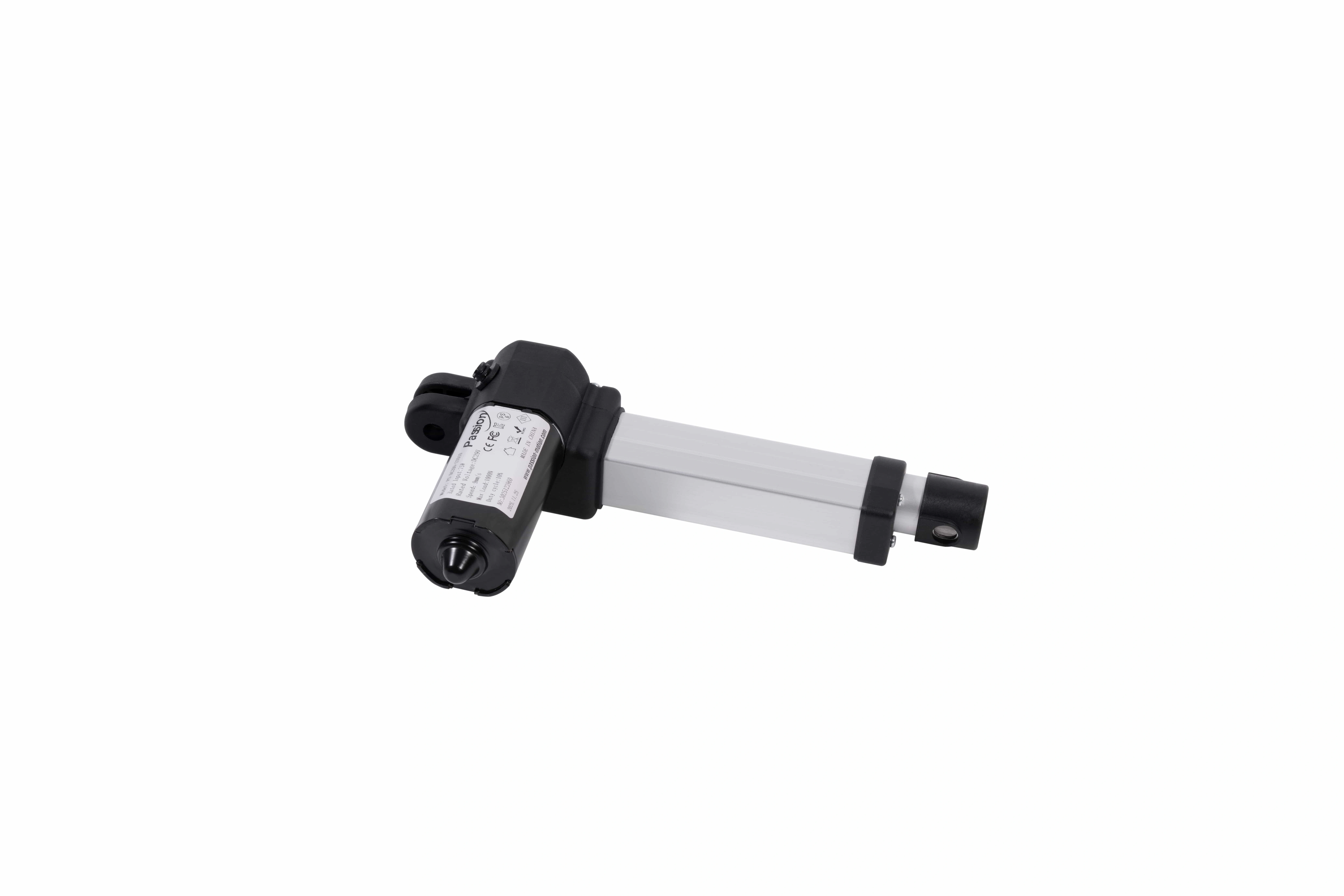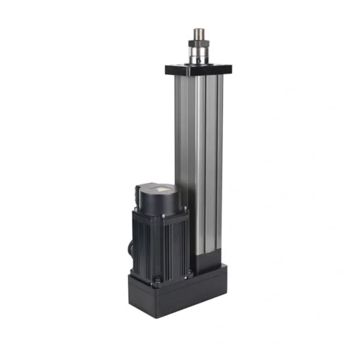

ZT20 Linear Actuator: 2000N, 4–20mm/s Speed
Check ZT20 specifications including DC 29V, up to 2,000N thrust, 4–20mm/s speed, 10–500mm stroke and compact mounting dimensions.
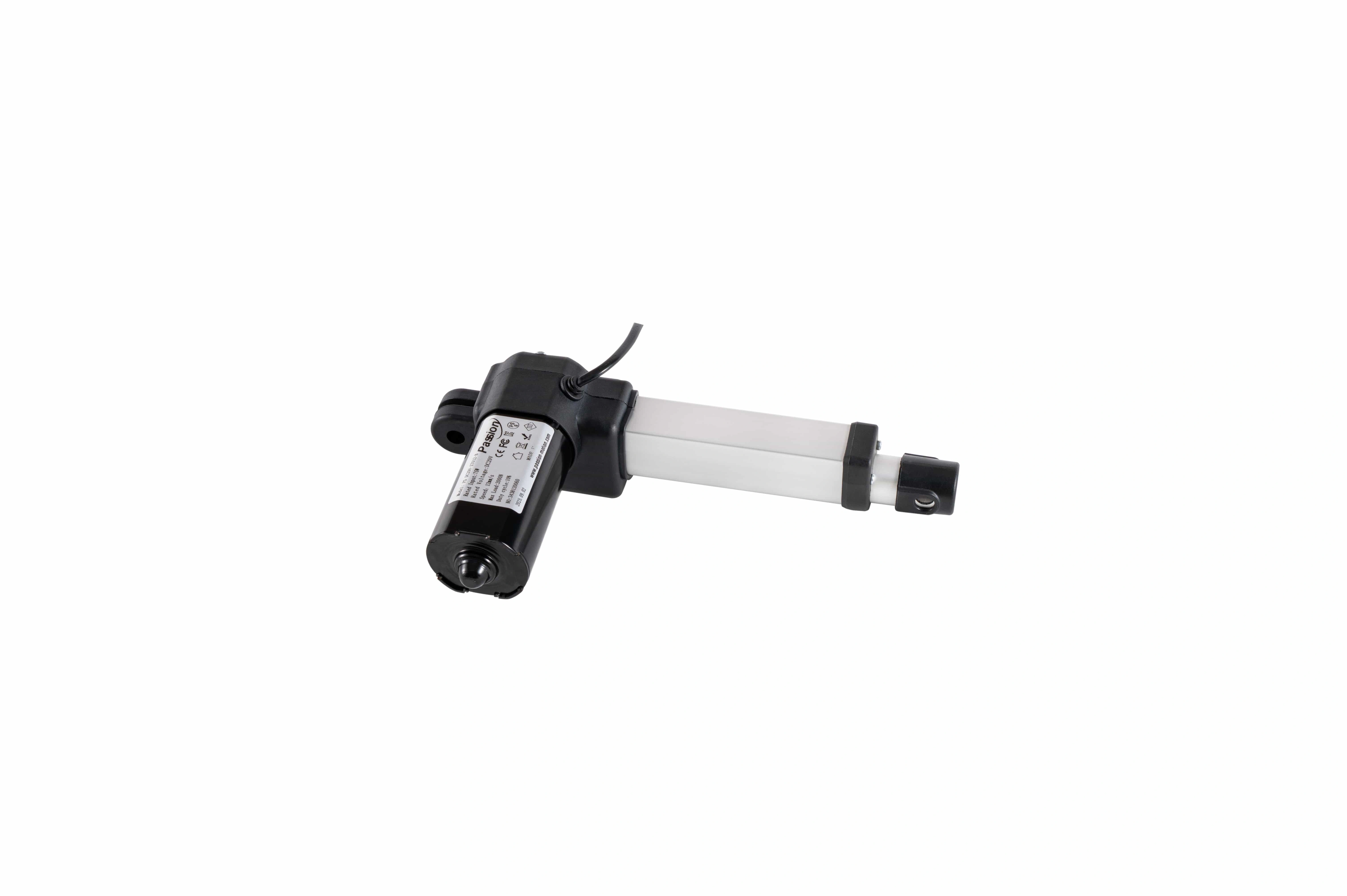
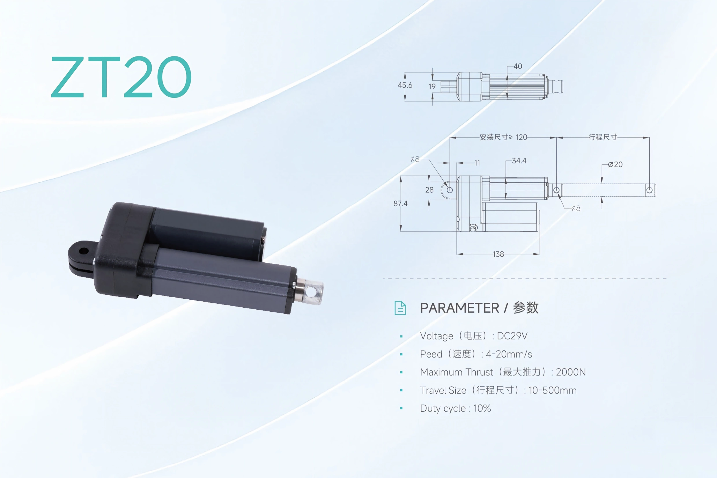
ZT20 Linear Actuator
Compact DC 29 V motion for applications requiring up to 2,000 N , a published 4–20 mm/s speed range and 10–500 mm stroke. Treat those figures as a configurable envelope rather than one guaranteed maximum combination.
Start with the real push / pull load.
The maximum thrust is a boundary, not proof of the highest speed and longest stroke at the same operating point.
Keep every published value visible, then focus the row that matters to the current decision.
Force, speed, stroke and duty cycle must be reviewed together. The interactive console above only changes review emphasis; it does not calculate an unverified combined performance point.
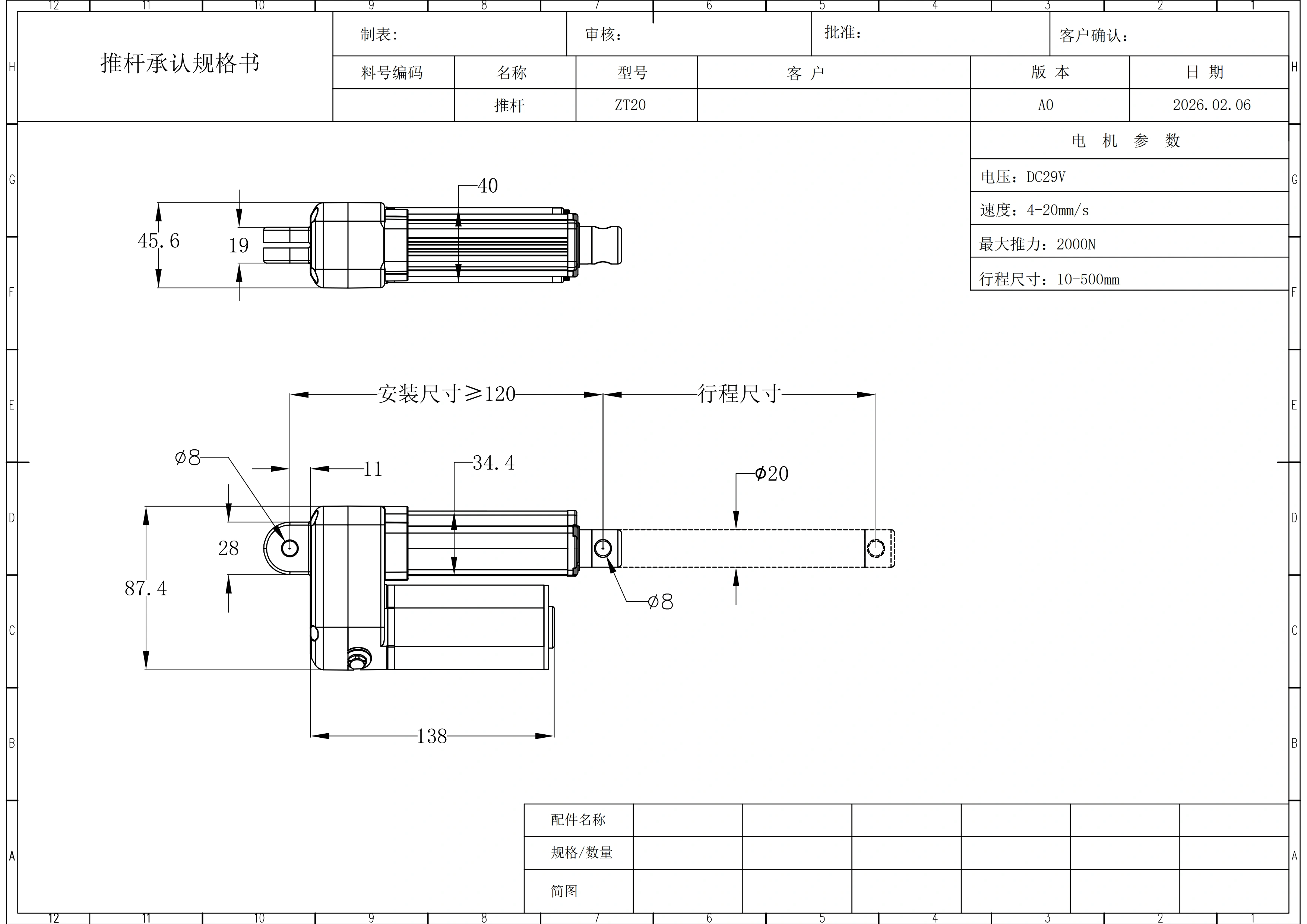
| Parameter | Published ZT20 value / engineering note |
|---|---|
| Maximum thrust | 2,000 N — maximum boundary; confirm the required loaded operating point. |
| Published speed range | 4–20 mm/s — do not assume 20 mm/s is available at every load and stroke. |
| Stroke range | 10–500 mm — selected travel must be checked against closed / extended clearance. |
| Duty cycle | 10% — plan run time and rest time around the real cycle pattern. |
| Rated voltage | DC 29 V |
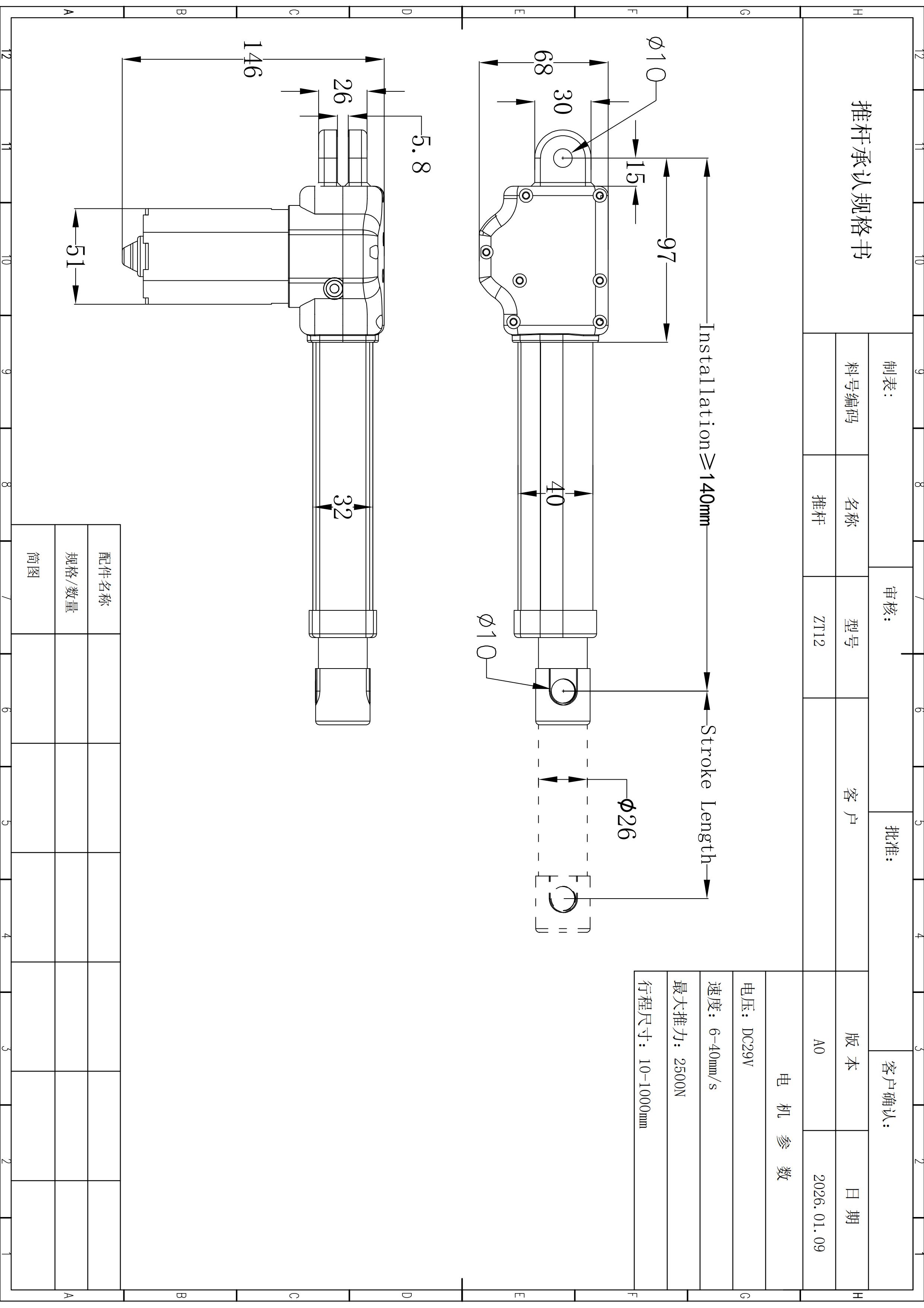
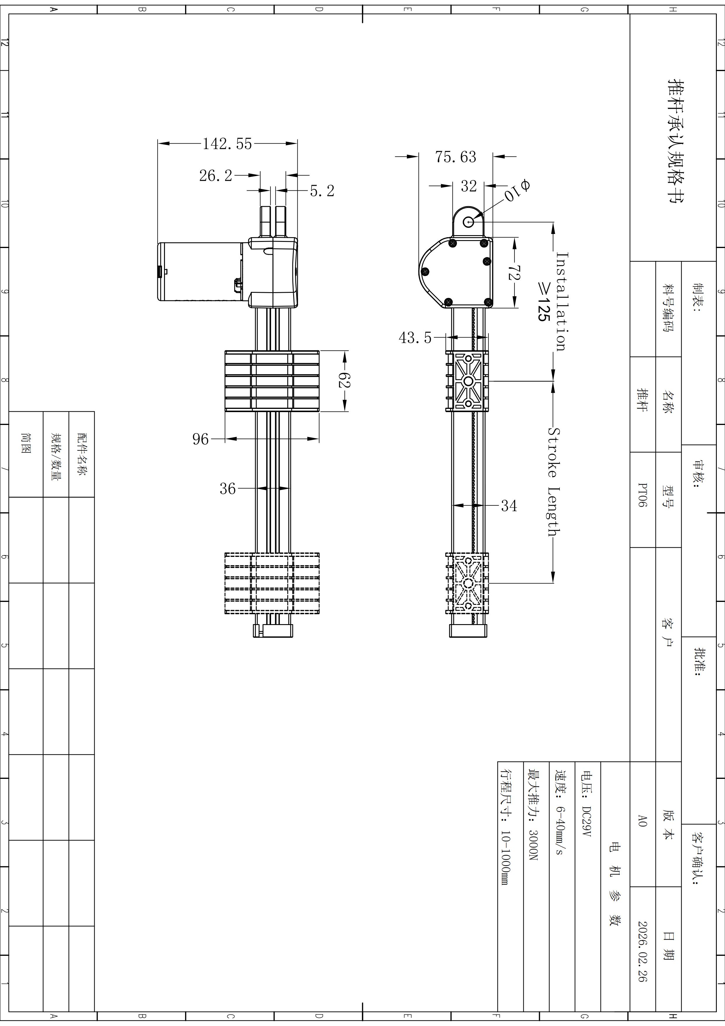
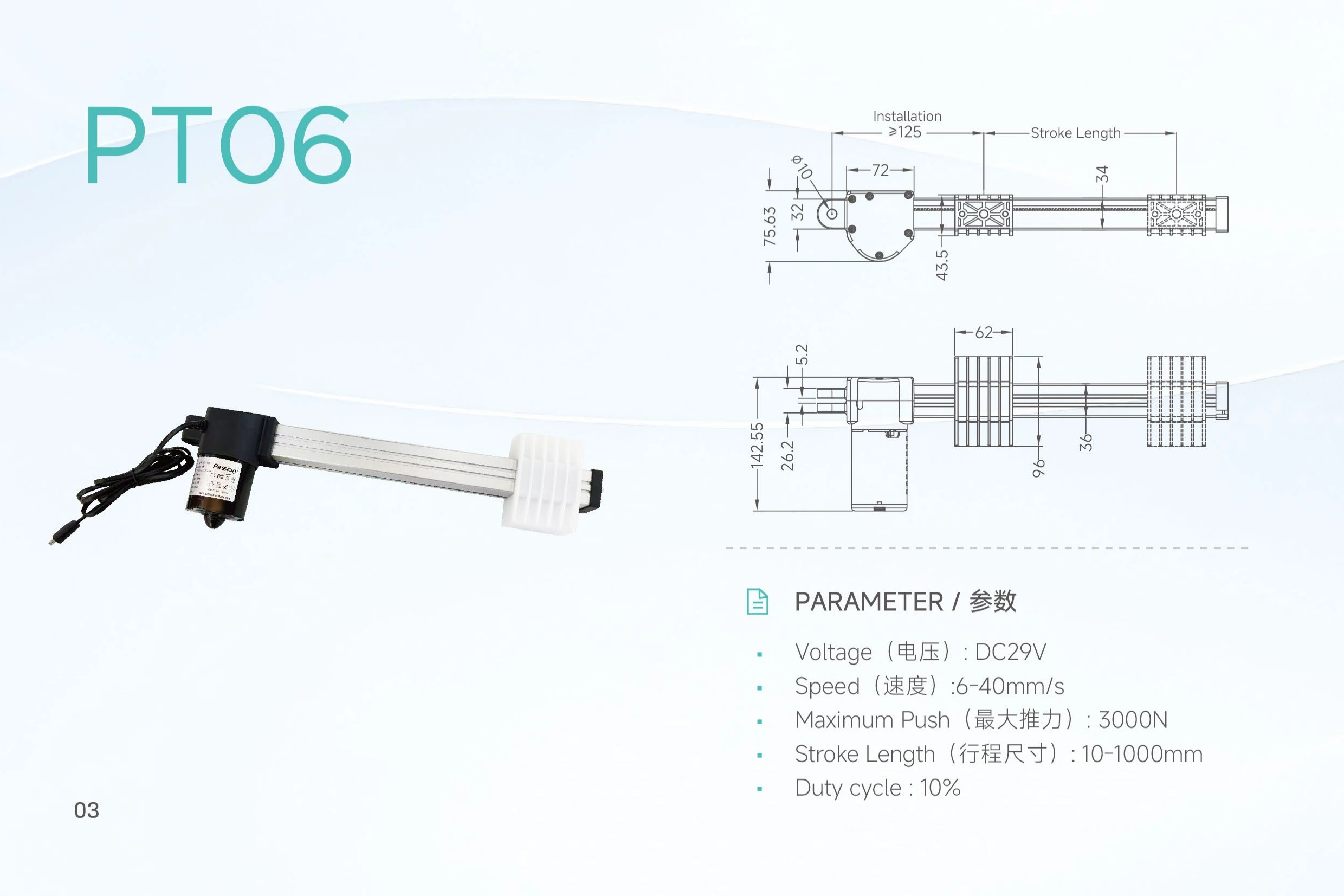
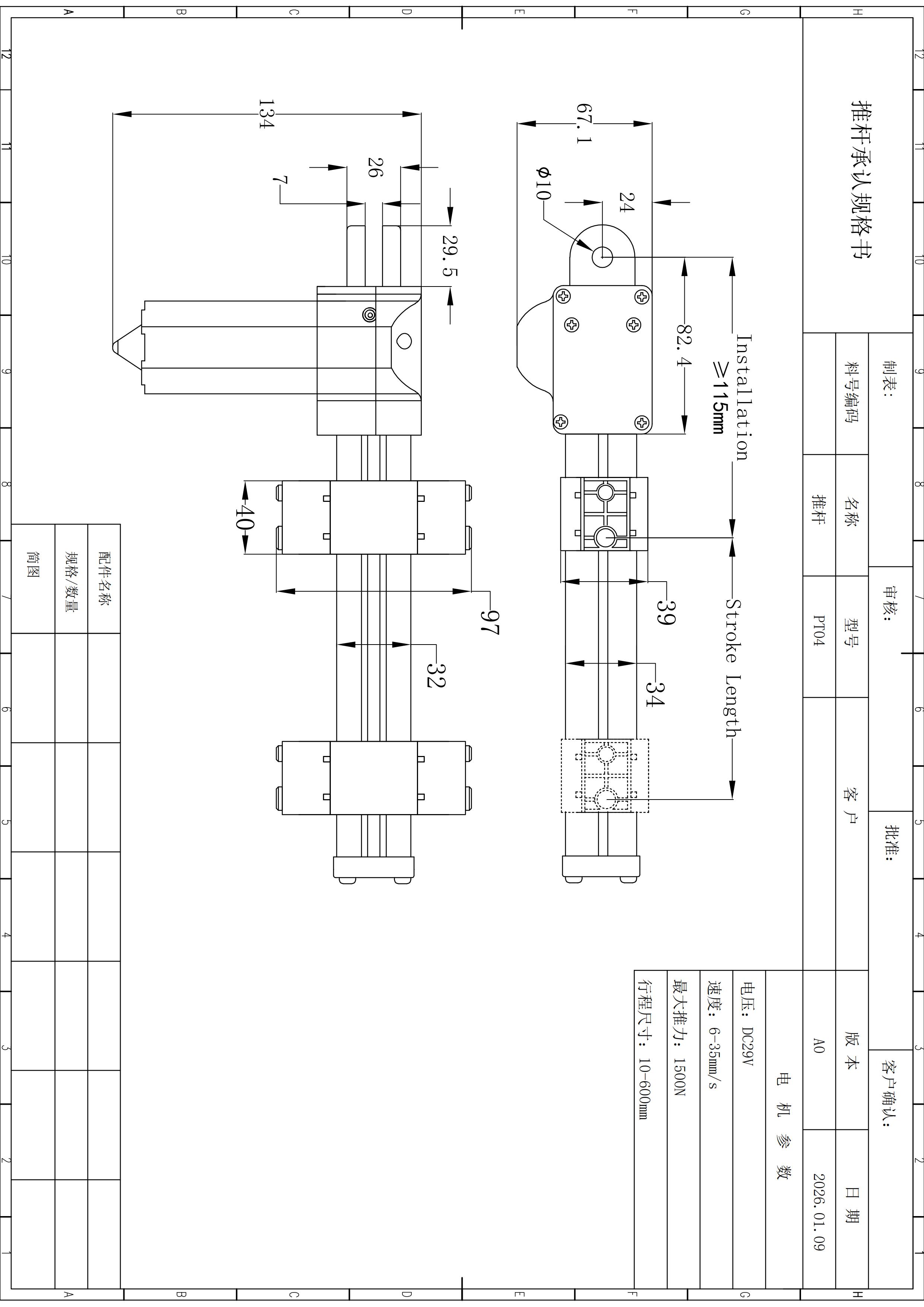
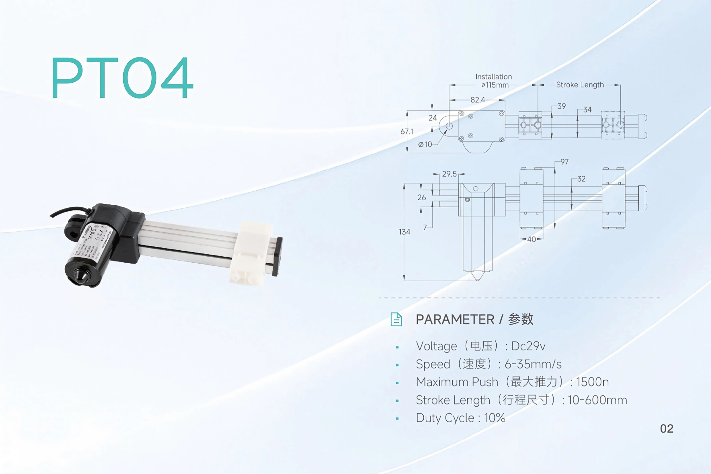
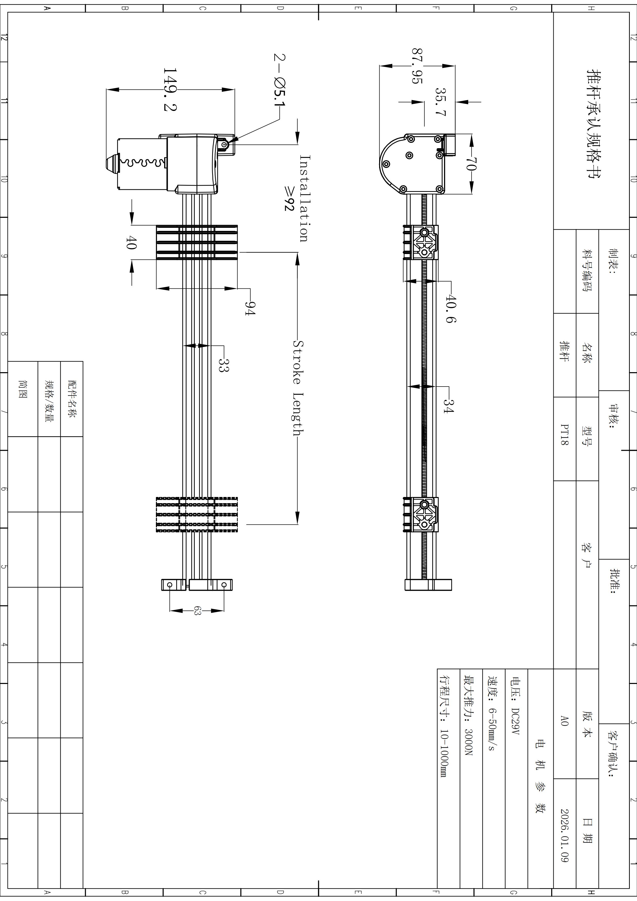
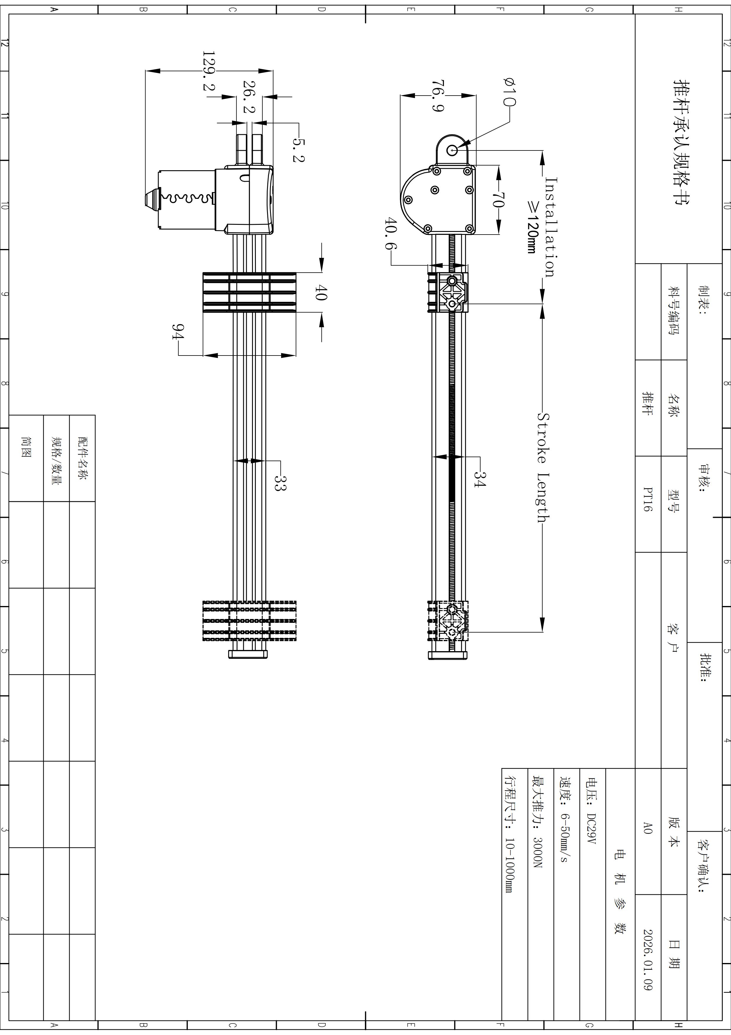
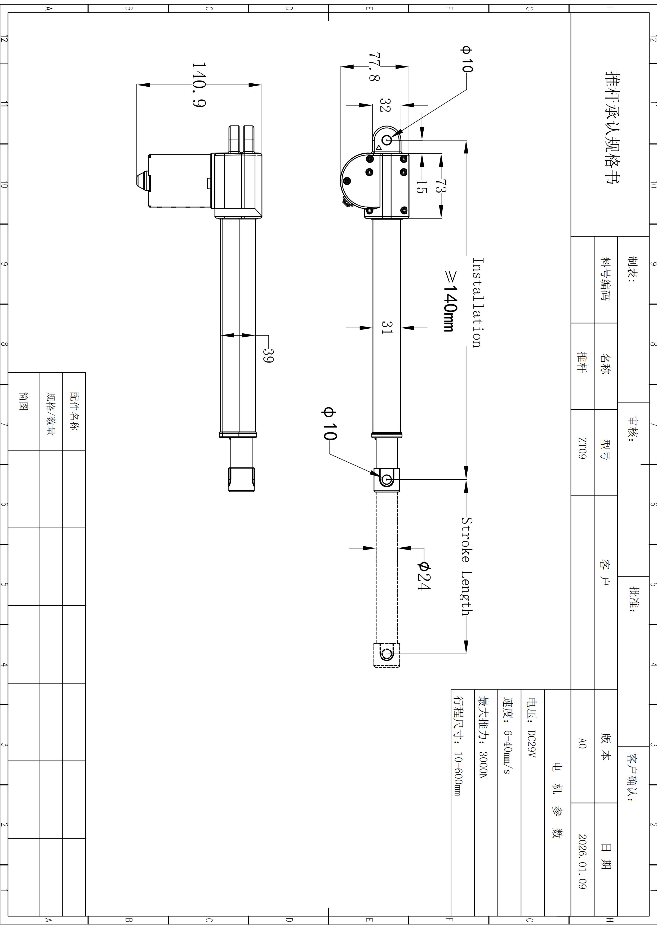
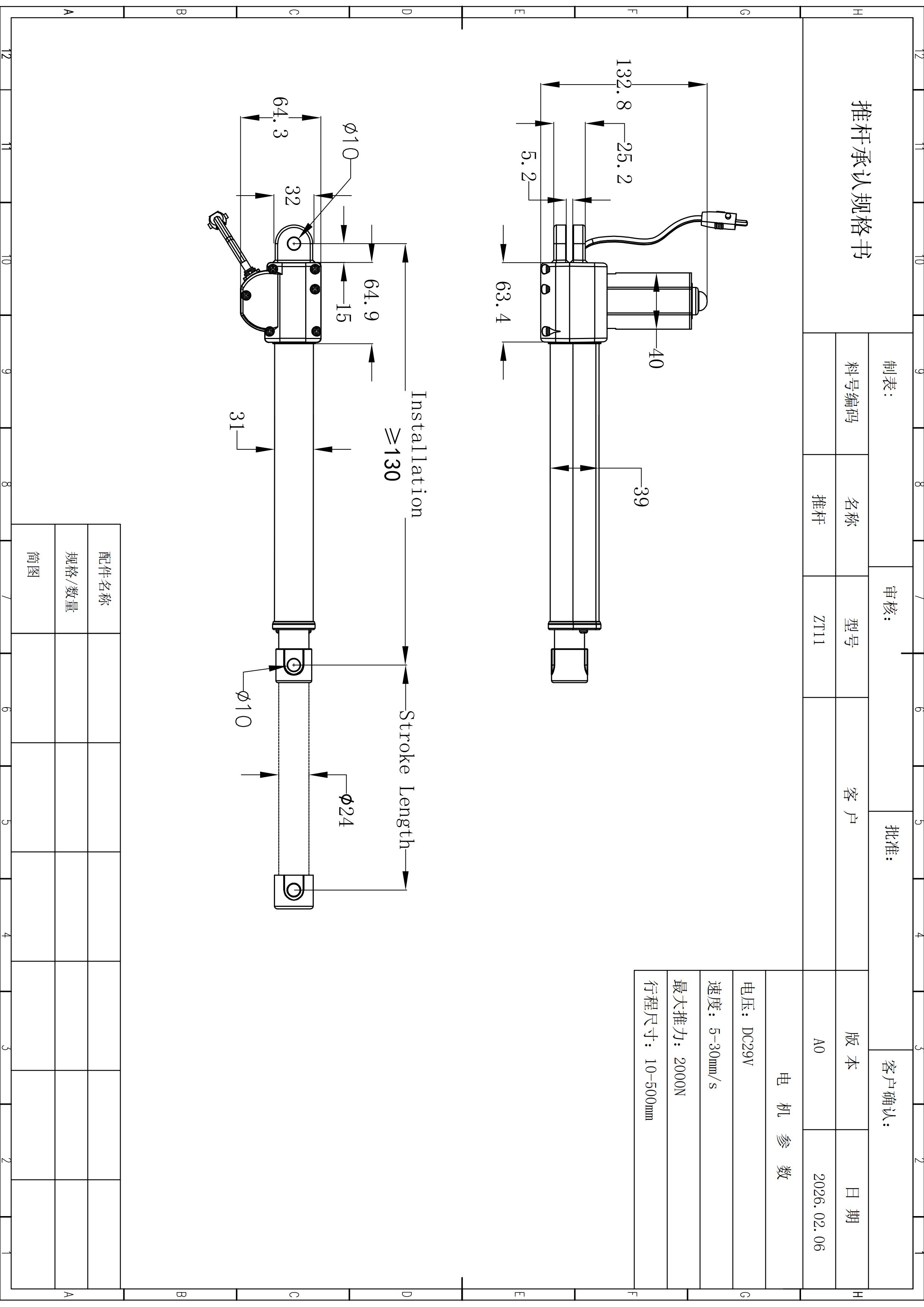
| Minimum installation size | ≥120 mm |
| Total base length | 138 mm |
| Rod diameter | Ø20 mm |
| Mounting-hole diameter | Ø8 mm |
| Additional width / thickness references | 45.6 mm, 40 mm, 34.4 mm |
| Additional height / offset references | 87.4 mm, 28 mm, 19 mm, 11 mm |
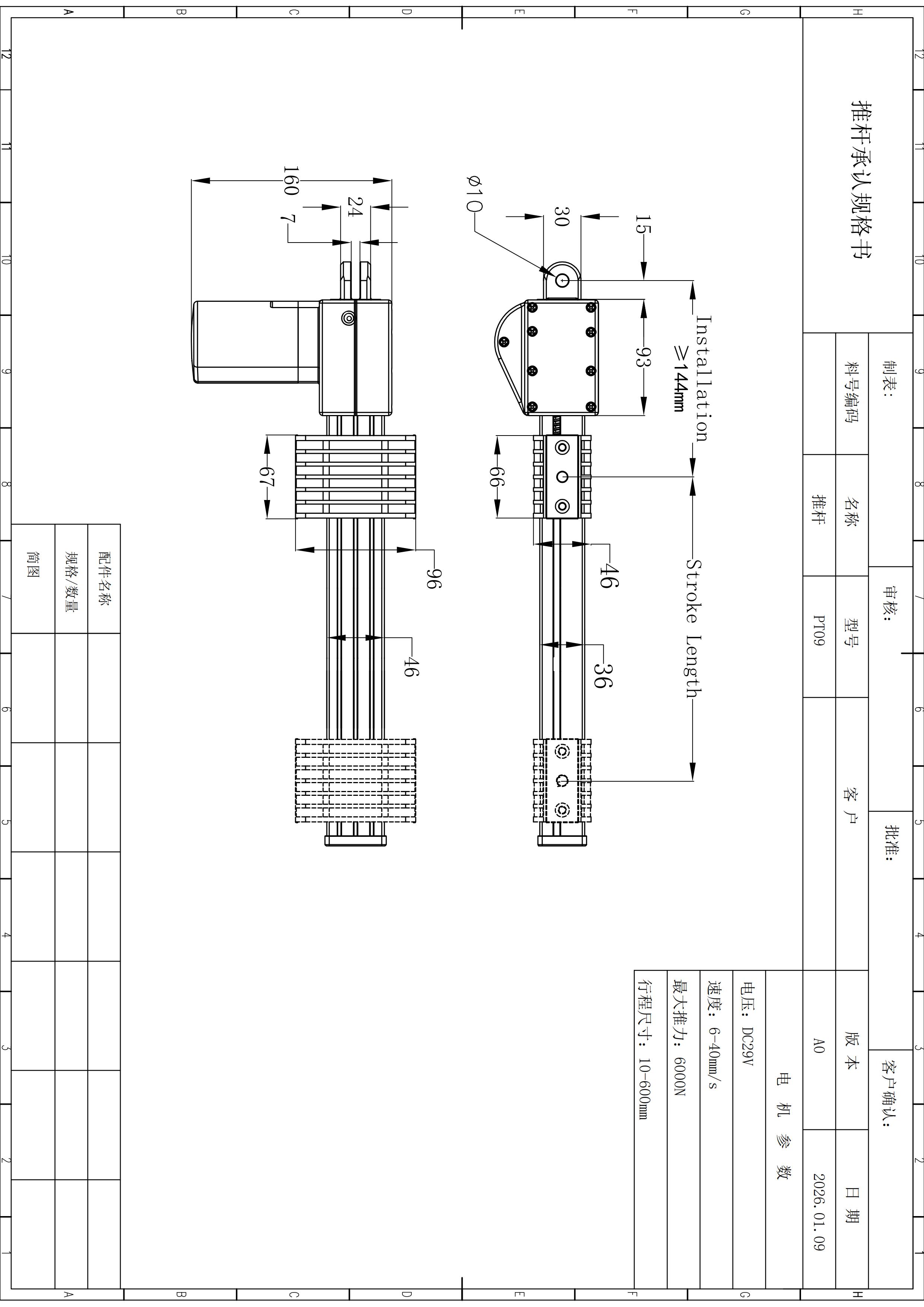
Use the dimensional references to reserve space before the surrounding mechanism is frozen.
Check retracted and extended clearance, pin-to-pin geometry, pivot angle, bracket alignment, cable routing, collision zones and side-load risk. Final manufacturing dimensions remain subject to the current project drawing.
A compact actuator still needs a complete operating pattern.
Record extension time, retraction time, pause time, cycles per hour, load in both directions and ambient conditions. ZT20’s 10% duty figure should not be read as unrestricted continuous motion.
Typical fit can include compact equipment adjustment, access panels or hatches, furniture positioning, light industrial mechanism adjustment, lifting or tilting assemblies, machine guards, mobile equipment subassemblies and custom automation modules. Suitability depends on the actual load path and configuration rather than the application label alone.
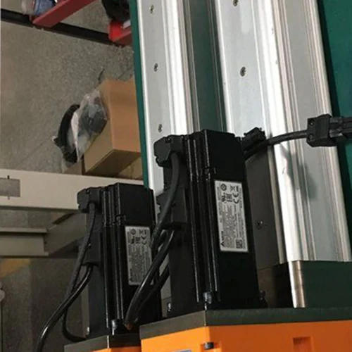
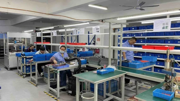
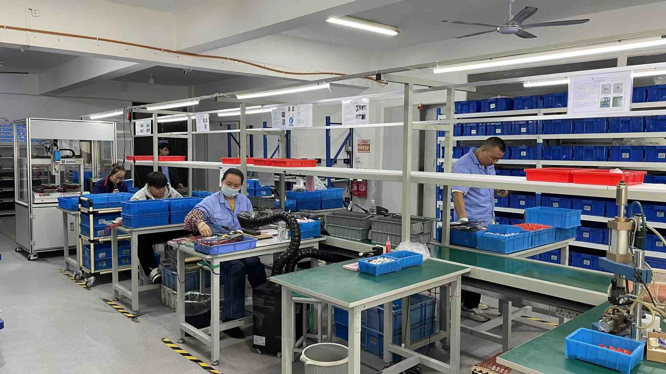
Inspect the production context without turning a photo into an unsupported quality claim.
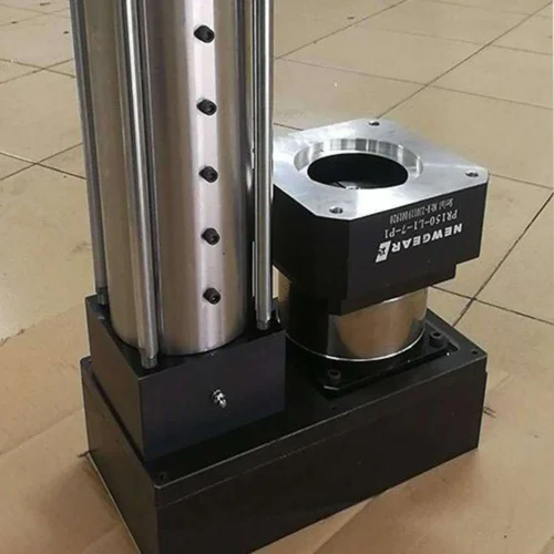
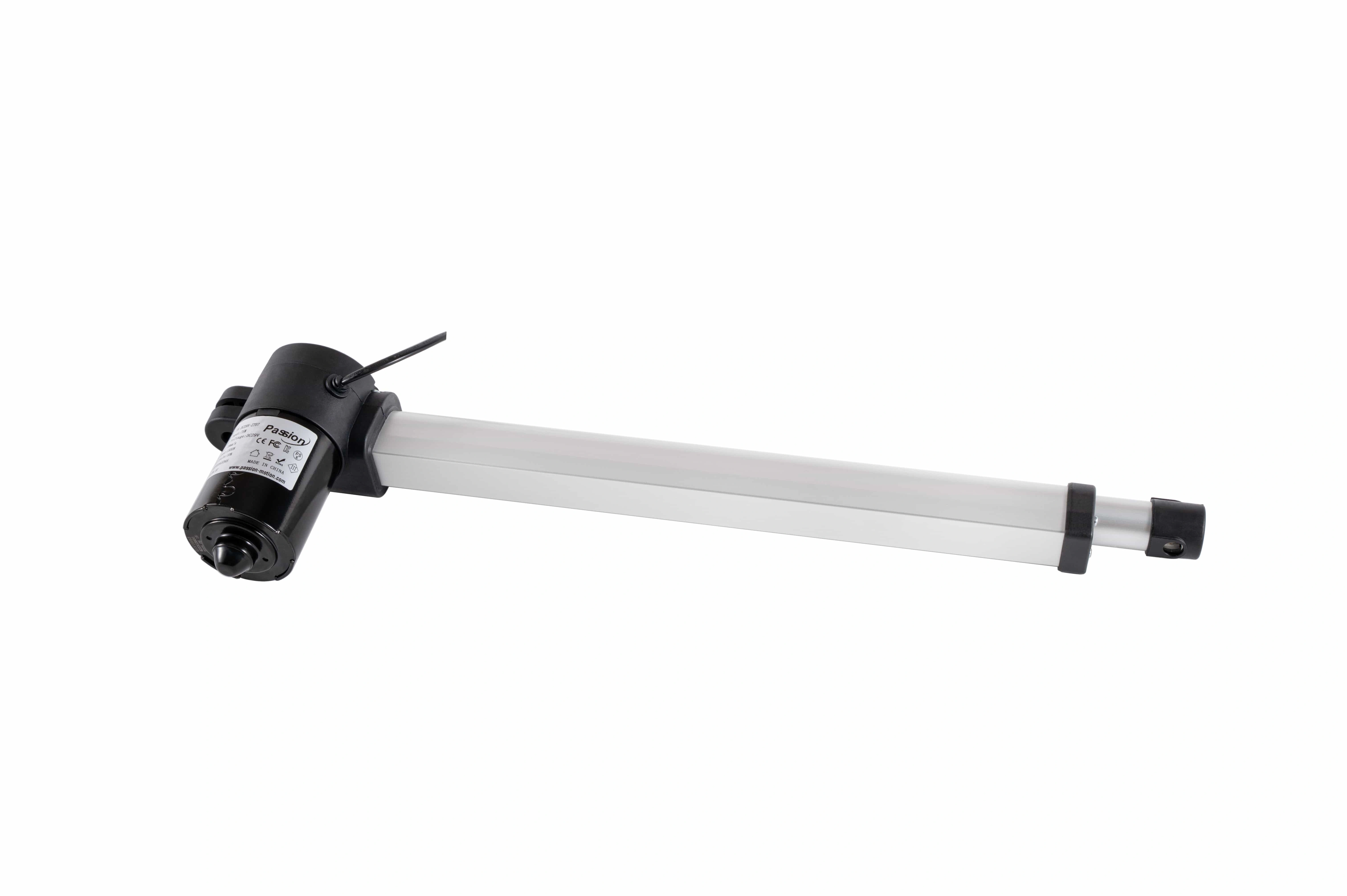
This first-party manufacturing image provides production context only. Final release still depends on the current drawing, configuration review and any project-specific test or documentation requirements.
Send the operating point, not just “ZT20”.
Include load, selected stroke, required loaded speed, DC 29 V power conditions, mounting geometry, run/rest pattern, feedback or control needs, environment, quantity and required drawings / test documents. Also confirm current draw, power-supply sizing, sensing, cable length, ingress needs and operating-temperature requirements where relevant.
Use the published figures as boundaries, then verify the selected configuration.
ZT20 combines DC 29 V operation, up to 2,000 N thrust, 4–20 mm/s published speed, 10–500 mm travel and a 10% duty cycle in a compact package.
What is the maximum thrust?
The documented maximum thrust is 2,000 N. Required loaded speed and selected stroke still need configuration review.
What speed range is listed?
The published range is 4–20 mm/s. It is a product range, not proof that every speed is available at every load and stroke.
What stroke range is available?
The documented travel range is 10–500 mm.
What is the minimum installation size?
The local ZT20 dimensional record lists an installation size of at least 120 mm.
What is the duty cycle?
ZT20 is documented at 10% duty cycle, so the motion sequence should include appropriate rest time.
Can I select ZT20 only from the 2,000 N figure?
No. Force, speed, stroke, duty cycle, mounting geometry, power and control requirements should be reviewed together.