

29V Actuator Power Supply Sizing: Current, Wattage, and Worked Examples

29V actuator power supply sizing should start with current, not with a familiar wattage label.
The correct supply has to support the required 29V bus, the continuous current of the motors and controller, short startup or peak events, the worst permitted simultaneous-motion condition, cable voltage drop, and the supply's real derating and overload behavior.
For OEM work, use this sequence:
- confirm the system is actually designed for a 29V DC bus;
- collect running, startup/peak, and current-limit data for every motor channel;
- add controller and accessory current;
- identify which motors may move or start together;
- calculate continuous and peak requirements separately;
- convert current to watts with P = V × I;
- check cable drop, connectors, fuse/current limits, derating, and overload mode;
- validate the production-intent system under worst-case conditions.
Core formulas
For a DC system:
Power (W) = Voltage (V) × Current (A)

Current (A) = Power (W) / Voltage (V)
For a 29V bus:
Power = 29 × Current
Current = Power / 29
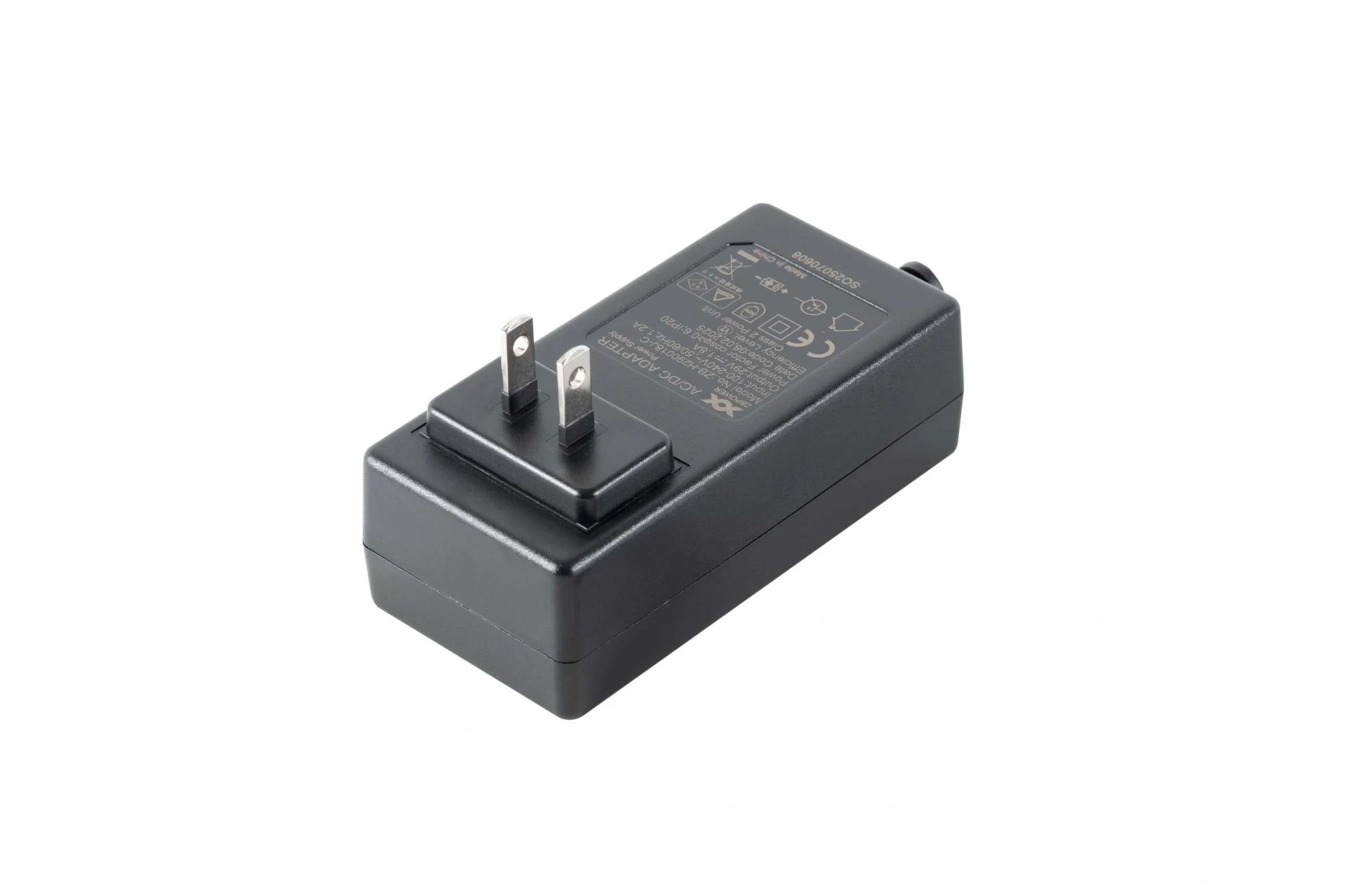
Supply sizing starts with required DC voltage, continuous current, startup/peak demand, and compatibility—not housing style.
These formulas are only the arithmetic layer. They do not tell you what current the motor actually draws. That value must come from released data or measurement at the intended operating point.
What data do you need before sizing?
Create a current-budget sheet with these fields:
| Input | Why it matters |
|---|---|
| Required bus voltage | establishes the supply output requirement |
| Motor running current | determines continuous load |
| Motor startup/peak current | tests short-term supply capability |
| Stall or controller current limit | defines worst fault/limit behavior |
| Motor count | establishes possible total load |
| Simultaneous-motion rules | determines which currents must be summed |
| Controller current | adds continuous electronics load |
| Accessories | handsets, radios, sensors, lighting, etc. |
| Duty cycle | affects thermal loading |
| Cable length/gauge | determines voltage drop |
| Ambient/input conditions | may reduce available supply output |
| Overload mode | determines behavior during motor transients |
If a datasheet gives only one current value, clarify what it represents before using it.
Continuous current formula
For a single motor:
I_continuous_required
= I_motor_running
+ I_controller
+ I_accessories
+ project-defined margin
For multiple motors that may run together:
I_continuous_required
= Σ I_running_of_simultaneous_motors
+ I_controller
+ I_accessories
+ project-defined margin
The margin should come from the project's engineering policy and the supply's actual derating behavior. There is no universal percentage that replaces the datasheet.
Peak current formula
Peak current is separate:
I_peak_required
= Σ I_start_or_peak_of_simultaneous_motors
+ I_controller
+ I_accessories
Then compare that result with:
- short-term overload capability;
- overload duration;
- current-limit mode;
- transient response;
- controller undervoltage threshold.
A supply may meet the continuous wattage requirement and still reset the controller during startup.
Worked example 1: one motor
The numbers below are hypothetical and are not ServoCylMotion model data.
Assume:
- bus voltage: 29V;
- loaded running current: 1.4 A;
- startup peak: 2.6 A;
- controller + accessories: 0.2 A;
- project-defined continuous design margin: 20%.
Step 1: continuous current
Base continuous current
= 1.4 + 0.2
= 1.6 A
Apply the hypothetical project margin:
1.6 × 1.20 = 1.92 A
Step 2: convert to watts
P = 29 × 1.92
  = 55.68 W
So the hypothetical continuous requirement is about 1.92 A / 55.7 W .
Step 3: check startup separately
I_peak = 2.6 + 0.2
       = 2.8 A
Peak output power at 29V is:
P_peak = 29 × 2.8
       = 81.2 W
This does not mean the supply must be continuously rated at exactly 81.2 W. It means its short-term behavior must support the real 2.8 A startup event for the required duration without an unacceptable voltage collapse or protection trip.
Worked example 2: two motors moving together
Again, all values are hypothetical.
Assume:
| Load | Running | Startup peak |
|---|---|---|
| Motor A | 1.1 A | 2.2 A |
| Motor B | 1.0 A | 2.0 A |
| Controller + accessories | 0.25 A | 0.25 A |
Both motors are allowed to run and start simultaneously.
Continuous requirement
Base current
= 1.1 + 1.0 + 0.25
= 2.35 A
With a hypothetical 20% project margin:
2.35 × 1.20
= 2.82 A
Convert to watts:
29 × 2.82
= 81.78 W
The hypothetical continuous target is therefore about 2.82 A / 81.8 W .
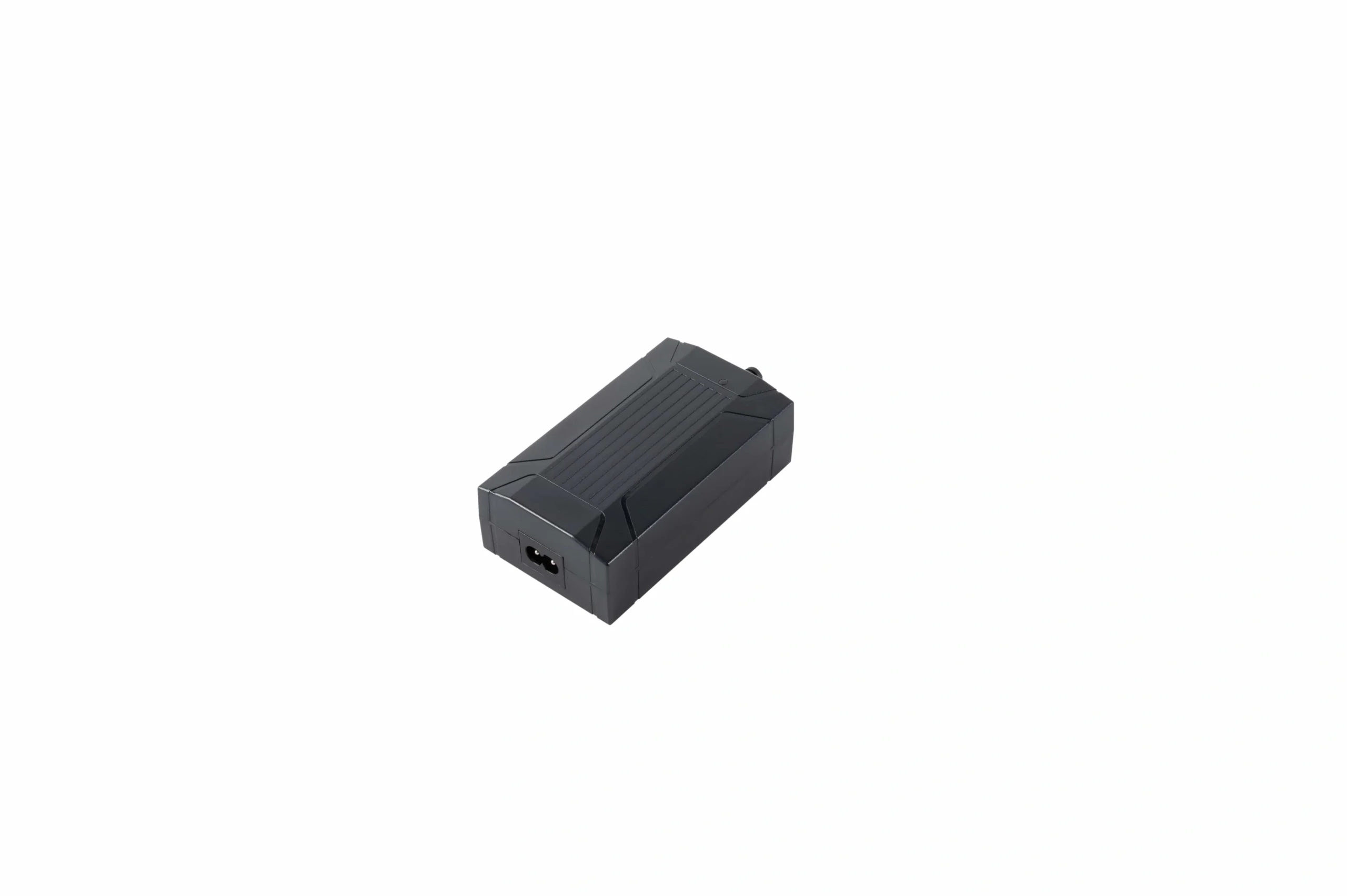
Multi-motor systems must be sized from the worst permitted simultaneous current state, then checked against the supply's continuous and peak behavior.
Peak requirement
Peak current
= 2.2 + 2.0 + 0.25
= 4.45 A
Equivalent instantaneous output power at 29V:
29 × 4.45
= 129.05 W
The engineer must now check whether the candidate supply can support that transient, how long it can do so, and what happens when its current limit is reached.
If motors are sequential, do not blindly add every peak
Some controllers never start two channels at the same time.
Others allow:
- independent channels;
- simultaneous movement;
- paired synchronized movement;
- sequential startup;
- a total-current ceiling.
Controller channel rules determine which motors can start or run together and therefore change the required current budget.
The supply calculation must match the controller logic .
A current table should therefore include a column called:
Can this load be active simultaneously?
This prevents unnecessary oversizing while still covering the real worst case.
52W, 58W, and 87W at 29V
At exactly 29V, ideal arithmetic gives:
| Output power | Current |
|---|---|
| 52 W | 1.79 A |
| 58 W | 2.00 A |
| 87 W | 3.00 A |
Calculation:
52 / 29 = 1.79 A
58 / 29 = 2.00 A
87 / 29 = 3.00 A
These are not recommendations for a specific motor or controller. They only convert wattage into ideal DC output current.
A 58 W supply is not automatically “for one motor,” and an 87 W supply is not automatically “for two motors.” Motor current, simultaneous operation, controller consumption, startup behavior, derating, and protection still decide the fit.
Why force is not enough to calculate current
A common sizing shortcut is:
The actuator produces X newtons, so it must draw Y amps.
That conversion cannot be made from force alone.
Current depends on:
- motor torque constant;
- gear ratio;
- screw lead;
- screw/gear efficiency;
- motor speed;
- acceleration;
- friction;
- controller current limiting;
- supply voltage;
- actual mechanical load.
Mechanical power can be approximated as:
Mechanical power = Force × Linear velocity
But electrical input power requires the efficiency of the complete motor/transmission/control chain.
For a production design, use the actual current data for the selected configuration or measure it under the intended load.
Size from the hard part of the cycle
Do not size the supply from the easy middle of travel if the mechanism is harder elsewhere.
The highest current may occur during:
- startup;
- lifting from the lowest point;
- unfavorable linkage geometry;
- acceleration;
- a high-friction position;
- simultaneous multi-axis motion;
- near-stall operation.
Measure or calculate the worst credible operating state.
Cable voltage drop
The supply output may be 29V while the controller sees less.
Basic relation:
V_drop = I × R_loop
Where R_loop includes:
- positive conductor;
- return conductor;
- connectors;
- contacts;
- switches/relays where applicable.
If the loop resistance is 0.20 Ω and current is 3 A:
V_drop = 3 × 0.20
       = 0.60 V
The controller would see roughly 28.4V before considering other dynamic effects.
Use real conductor resistance, cable length, connector resistance, and maximum current.
Connector and wire heating
Resistive loss follows:
P_loss = I² × R
This is why a connector that appears acceptable during a 1 A bench test can heat much more at 3 A.
Check:
- wire gauge;
- connector current rating;
- contact resistance;
- pin count;
- crimp quality;
- cable bundling;
- enclosure temperature.
The harness is part of the power system.
Derating: headline wattage may not be fully available
Power supplies often have derating curves.
Manufacturers may reduce allowed output as:
- ambient temperature rises;
- AC input falls;
- airflow changes;
- mounting orientation changes;
- enclosure conditions worsen.
XP Power and Mean Well both publish guidance around reading and applying derating curves.
Do not replace the real curve with a universal rule.
If a supply is nominally 87 W but the datasheet allows only 80% output at the project's ambient condition, the usable continuous power is:
87 × 0.80
= 69.6 W
That example is hypothetical. Use the actual candidate's curve.
Overload mode matters for motor startup
Two supplies with the same nominal wattage may behave differently above rated current.
Possible modes include:
- constant-current limiting;
- foldback;
- hiccup/restart;
- shutdown;
- latch-off;
- automatic recovery.
For a motor load, ask:
- What happens when startup exceeds the continuous rating?
- How long is peak output allowed?
- Does the voltage collapse?
- Does the controller reset?
- Does the supply recover automatically?
- Does repeated startup cause thermal shutdown?
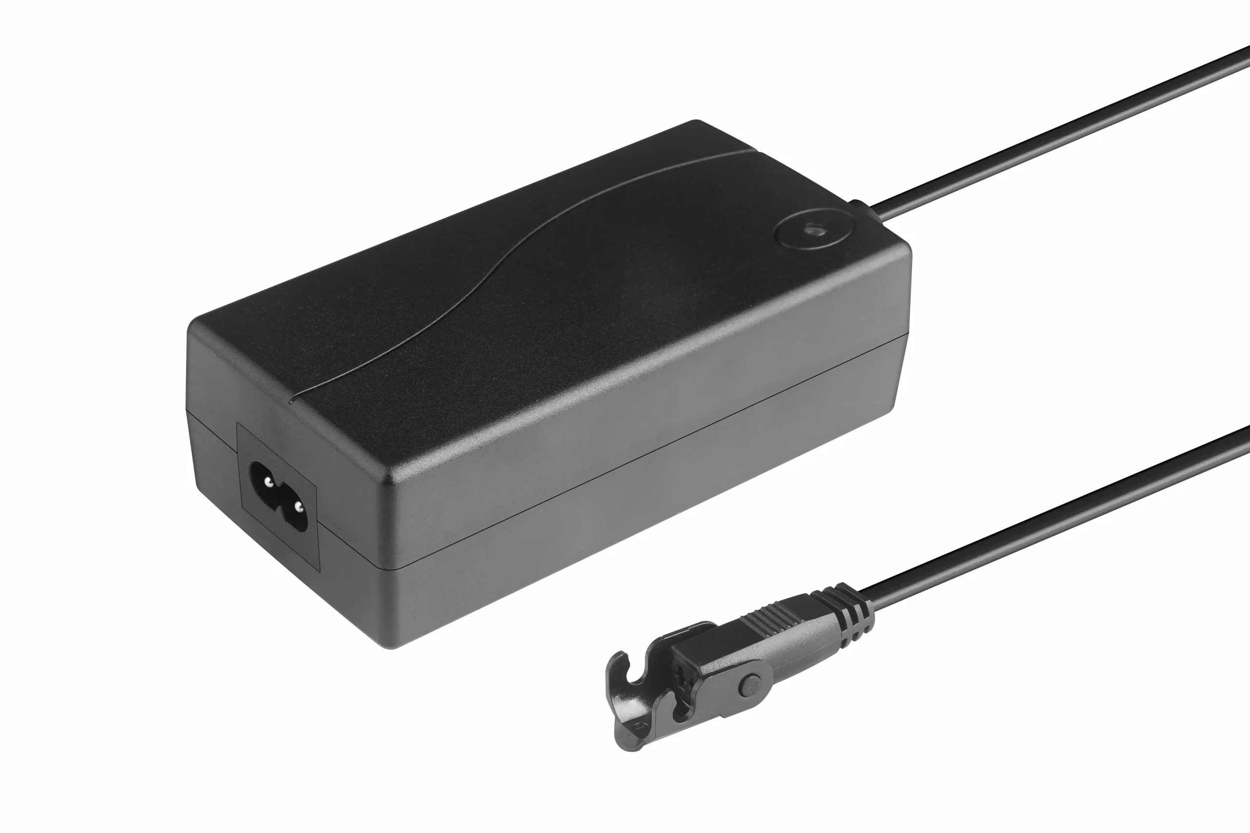
Headline wattage is not enough; check temperature/input derating, overload mode, recovery, connector limits, and the validated duty cycle.
A supply that repeatedly enters hiccup mode during normal motion is not a good system match even if the printed wattage looks sufficient.
Duty cycle changes the thermal requirement
A motion system that runs for 10 seconds every ten minutes is different from one that cycles repeatedly.
Record:
- motor run time;
- rest time;
- cycles per hour;
- simultaneous channels;
- peak duration;
- ambient temperature;
- enclosure temperature.
Validate the real cycle while monitoring the supply, controller, connectors, and bus voltage.
AC input conditions can also reduce available output
The DC side is not the only variable.
Check:
- rated AC input range;
- low-line input behavior;
- mains frequency;
- regional supply conditions;
- derating at low input;
- power-factor requirements where relevant.
Regional plug formats are a separate BOM topic, but the electrical input range still belongs in the supply specification.
Supply-sizing worksheet
Before choosing a supply, complete this table:
| Field | Project value |
|---|---|
| Required DC output | 29V + documented tolerance |
| Motor A running current | ___ A |
| Motor A startup/peak | ___ A |
| Motor B running current | ___ A |
| Motor B startup/peak | ___ A |
| Simultaneous-motion rule | ___ |
| Controller current | ___ A |
| Accessory current | ___ A |
| Continuous current total | ___ A |
| Peak current total | ___ A |
| Project margin | ___ |
| Required continuous watts | ___ W |
| Required transient capability | ___ A for ___ ms/s |
| Cable voltage drop | ___ V |
| Ambient / enclosure temp | ___ °C |
| Derating result | ___ W / A |
| Overload mode | ___ |
| Connector/pinout | ___ |
| Validation status | pass / open |
BOM freeze checklist
After validation, freeze:
- supply model/revision;
- output voltage and tolerance;
- continuous current;
- peak/overload behavior;
- AC input range;
- derating curves;
- DC connector/pinout;
- cable gauge and length;
- fuse/current limit;
- controller configuration;
- allowed simultaneous motion;
- firmware/parameters;
- approved motor configuration.
Use the system compatibility resource to verify the selected supply, controller, motors, connectors, and feedback architecture as one system.
When the calculated requirements are known, compare them with the documented 29V power-supply family rather than choosing by wattage first.
Validation checklist
Electrical
- no-load output voltage;
- loaded output voltage;
- running current;
- startup current;
- simultaneous-motor current;
- current-limit behavior;
- controller reset threshold.
Wiring
- voltage at controller;
- voltage at motor;
- connector temperature;
- cable temperature;
- ground-return drop.
Supply
- low-line AC input;
- high ambient;
- overload recovery;
- thermal shutdown behavior;
- repeated startup.
System
- worst mechanical load;
- highest-friction position;
- full duty cycle;
- multi-axis operation;
- stall/obstruction response;
- fault/reset sequence.
Record the exact hardware, firmware, harness, and parameter revision used in validation.
FAQs
How do I convert current to watts at 29V?
Use P = 29 × I. For example, 2 A corresponds to 58 W and 3 A corresponds to 87 W at exactly 29V.
Should I size the supply from running current or startup current?
Use both. Continuous capacity is based on the sustained current and duty cycle, while short-term supply behavior must support startup/peak events without unacceptable voltage collapse or protection trips.
How do I size a supply for two motors?
Sum the running currents of motors allowed to run together, then separately sum startup/peak currents for motors allowed to start together. Add controller/accessory loads and apply the project's validated margin/derating method.
Is 20% margin always enough?
No. A percentage margin is project-specific. Use the candidate supply's derating curves, actual load uncertainty, environment, overload mode, and validation evidence.
Can I estimate current from actuator force?
Not reliably from force alone. Motor constants, gearing, screw lead, efficiency, speed, friction, and controller behavior are also required.
Why can a supply with enough watts still fail?
Motor startup can exceed the continuous current rating, cable voltage drop can reduce controller voltage, or the supply may enter hiccup/foldback/shutdown mode during a normal transient.
References
- Progressive Automations — Choosing a Power Supply
- Electronica Embajadores — 29 V / 2 A Supply Example
- Iris Dynamics — Selecting a Power Supply for a Linear Actuator
- Firgelli — Choosing the Correct Power Supply
- XP Power — Understanding Power-Supply Derating
- Mean Well Power Supplies — Reading a Derating Curve
