

Actuator Control System Guide: Architecture, Feedback, Power, and Interfaces

An actuator control system is not just a box that makes a motor extend and retract. For an OEM engineer, it is the complete chain that turns a command into controlled motion and then decides what to do with feedback, limits, faults, communication loss, and power conditions.
That chain can be simple—a switch, relay, DC source, and two-wire motor—or much more structured, with a PLC, motion logic, feedback sensors, multi-axis coordination, network communication, diagnostics, and commissioning states.
The right architecture depends on what the machine must know and control. If the only requirement is end-to-end travel, a basic open-loop arrangement may be enough. If the system must reach intermediate positions, hold synchronization under unequal loads, detect following error, report faults, or recover from power loss in a defined way, the control architecture must become more explicit.
This guide explains the system layers, where open- and closed-loop control differ, how feedback changes capability, and which interfaces an OEM team should freeze before selecting hardware.
The complete control architecture
A useful way to define actuator control systems is as a set of functional layers.
Operator / HMI / Remote / Machine Command
                  |
                  v
      Supervisory Logic / PLC / State Machine
        |          |            |
        |          |            +--> faults, interlocks, reset, homing
        |          |
        |          +--> feedback and status
        v
       Drive / Power Stage  <------  Feedback / Sensors
        |                            ^
        | motor power                |
        v                            |
      Motor + Gearbox + Screw + Mechanical Load
                  ^
                  |
          Power Source / Distribution
The exact implementation varies. Some systems integrate several layers in one enclosure. Others separate the PLC, motor drive, DC source, feedback electronics, and user interface.
The engineering task is therefore not to copy one diagram literally. It is to define which layer owns each function and which interfaces connect the layers .
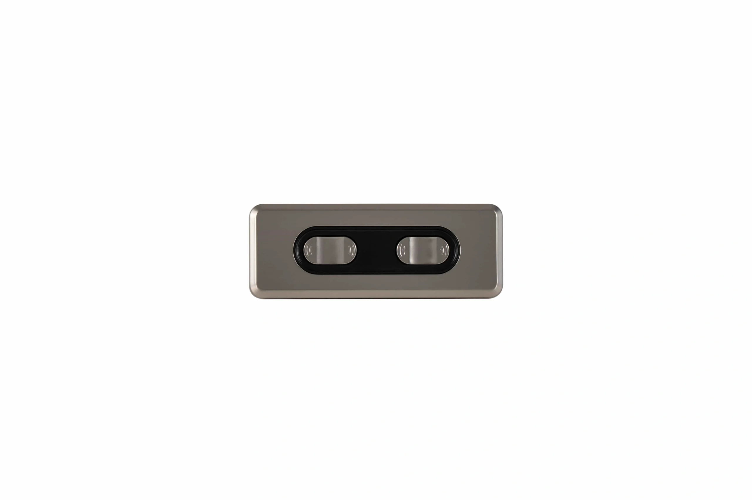
A control architecture should define command, channel, feedback, and power interfaces before parts are selected.
Layer 1: command and user interface
The command layer answers: who is allowed to request motion?
Possible inputs include:
- momentary up/down buttons;
- maintained switches;
- a local keypad or HMI;
- analog setpoints;
- digital I/O;
- PLC commands;
- a machine network;
- a wired pendant;
- RF or Bluetooth command devices.
The requirements should define command priority, enable conditions, manual versus automatic modes, and what happens when the command source disappears.
For example, if local service controls and automatic PLC commands both exist, the control specification should state which one has authority and whether entering service mode inhibits remote motion.
Layer 2: supervisory logic and state management
The logic layer answers: what is the system allowed to do now?
A practical state machine may include:
- power-up / uninitialized;
- safe disabled;
- ready;
- manual jog;
- automatic motion;
- homing;
- controlled stop;
- faulted;
- reset pending;
- service mode.
This layer owns sequencing, interlocks, mode changes, diagnostics, homing permissions, and fault recovery. It should also define what happens after power loss, communication loss, a limit event, feedback loss, or a stalled motor.
For OEM programs that need project-level control integration rather than only educational background, ServoCylMotion's control-system OEM capability is the commercial bridge.
Open-loop vs closed-loop control
The most important architecture decision is whether the system needs to measure the result of motion and correct it.
| Question | Open-loop approach | Closed-loop approach |
|---|---|---|
| Does the controller measure actual motion? | Not continuously | Yes |
| Can it directly correct position error? | No | Yes, within system limits |
| Intermediate positions | Approximate or timing-based | Measured and controlled |
| Load-change compensation | Limited | Possible |
| Synchronization under unequal load | Weak | Practical with suitable feedback and logic |
| Typical added hardware | switch, relay, timer, basic drive | sensor, feedback interface, controller/drive |
| Main engineering risk | drift and unverified motion | sensor faults, scaling errors, tuning, feedback loss |
Open-loop control can be appropriate when the motion task is simple and the system does not need to know the exact intermediate position.
Closed-loop control adds a measured variable—such as position, speed, or current—and compares actual behavior with the command. The system can then reduce the error rather than assuming that applying power produced the expected result.
The important point is that closed-loop control is not automatically “more accurate” in every installation. Accuracy still depends on sensor location, resolution, mechanical backlash, compliance, calibration, sampling, control tuning, and the relationship between the sensor and the actual load.
Drive and power are separate from control logic
A PLC or microcontroller can decide what motion should occur, but it usually does not directly deliver the motor current required to move the load. That is the job of the drive or power stage.
Common conceptual approaches include:
Relay or contactor reversal
A basic DC motor can be driven forward or reverse by switching polarity. Relays or contactors can implement this simply, but the architecture usually offers limited speed control and limited position regulation unless feedback and additional logic are added.
H-bridge drive
An H-bridge reverses motor current electronically. With pulse-width modulation, the drive can also vary effective motor voltage and speed.
The OEM specification should define:
- motor voltage range;
- continuous current;
- peak or startup current;
- braking or coasting behavior;
- current limiting;
- fault output;
- thermal limits;
- required switching behavior.
Servo-style drive
More advanced drives may close current, speed, and/or position loops locally. The supervisory controller then sends commands and receives status instead of directly switching motor current.
The architecture must make clear which loop is closed where. Otherwise two parts of the system may both try to regulate the same behavior—or neither may own it.
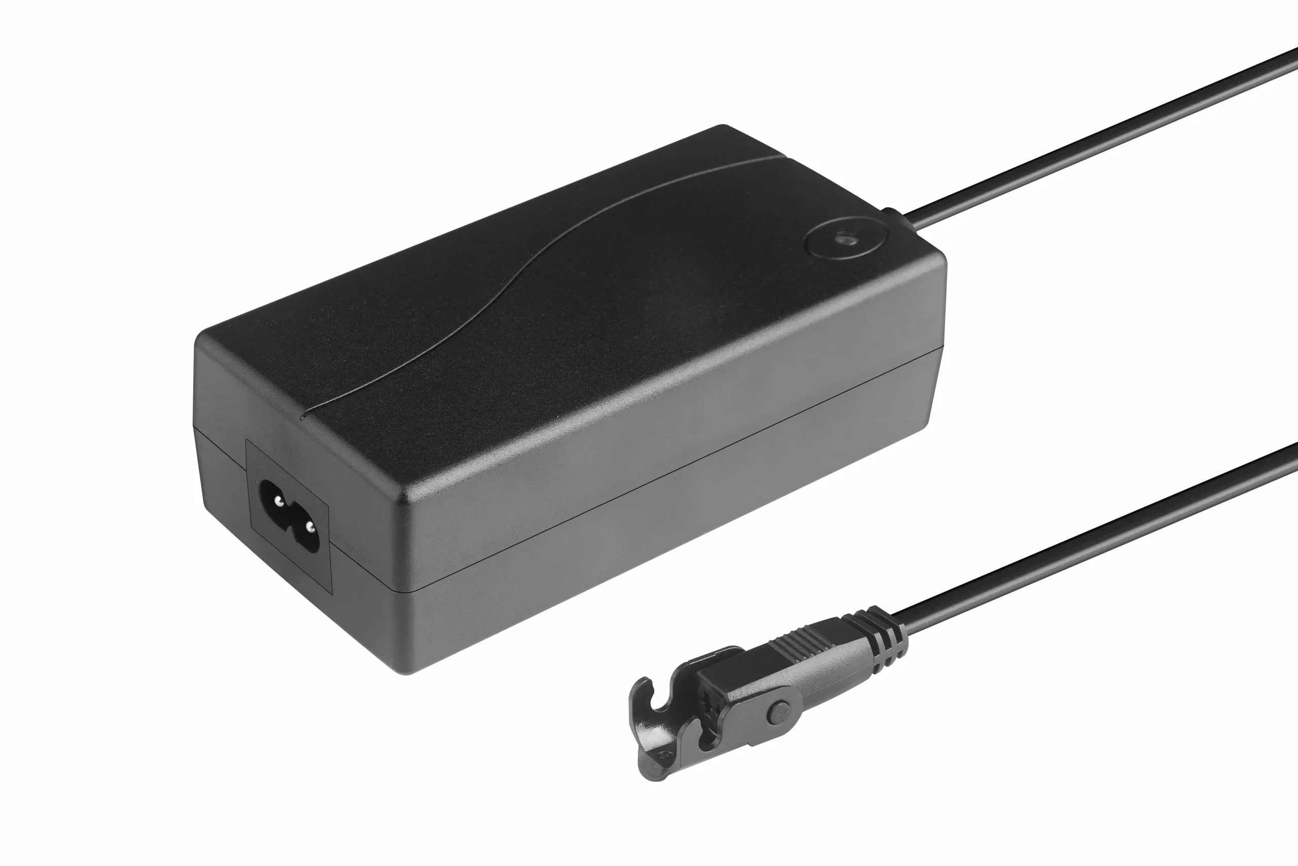
The power layer must be sized and released together with the drive and actuator load requirements.
Size the power layer for the motion case
Power requirements should be based on the worst credible operating case, not only a nominal running value.
Freeze:
- allowable supply range;
- continuous and peak current;
- number of simultaneously moving axes;
- startup or stall behavior;
- voltage-drop limits;
- conductor size;
- connector current rating;
- fusing and disconnect strategy;
- grounding and EMC expectations;
- thermal environment.
A system can have correct control logic and still fail because the power path is undersized.
Feedback determines what the system can know
Feedback is the information path from the motion back to the control logic.
Common feedback concepts include:
Limit switches
Limit switches can tell the system that the mechanism reached an end condition. They are useful for endpoint protection or status but do not normally provide continuous position.
Potentiometer feedback
A potentiometer can provide an analog signal related to stroke position. The control design still needs scaling, plausibility checks, electrical conditioning, and a strategy for noise or wear.
Hall or pulse feedback
Pulse feedback can provide speed and incremental position information. If the system loses its accumulated reference, it may need a reset or homing process.
Encoders
Incremental encoders provide relative position and speed information. Absolute feedback can retain or directly report position, depending on the sensor architecture.
The key compatibility question is not simply “does the actuator have feedback?” It is:
- what signal does it produce?
- what voltage or electrical interface does it require?
- how is direction represented?
- what resolution or scaling applies?
- does the control logic understand that signal?
- what happens when the signal is missing or implausible?
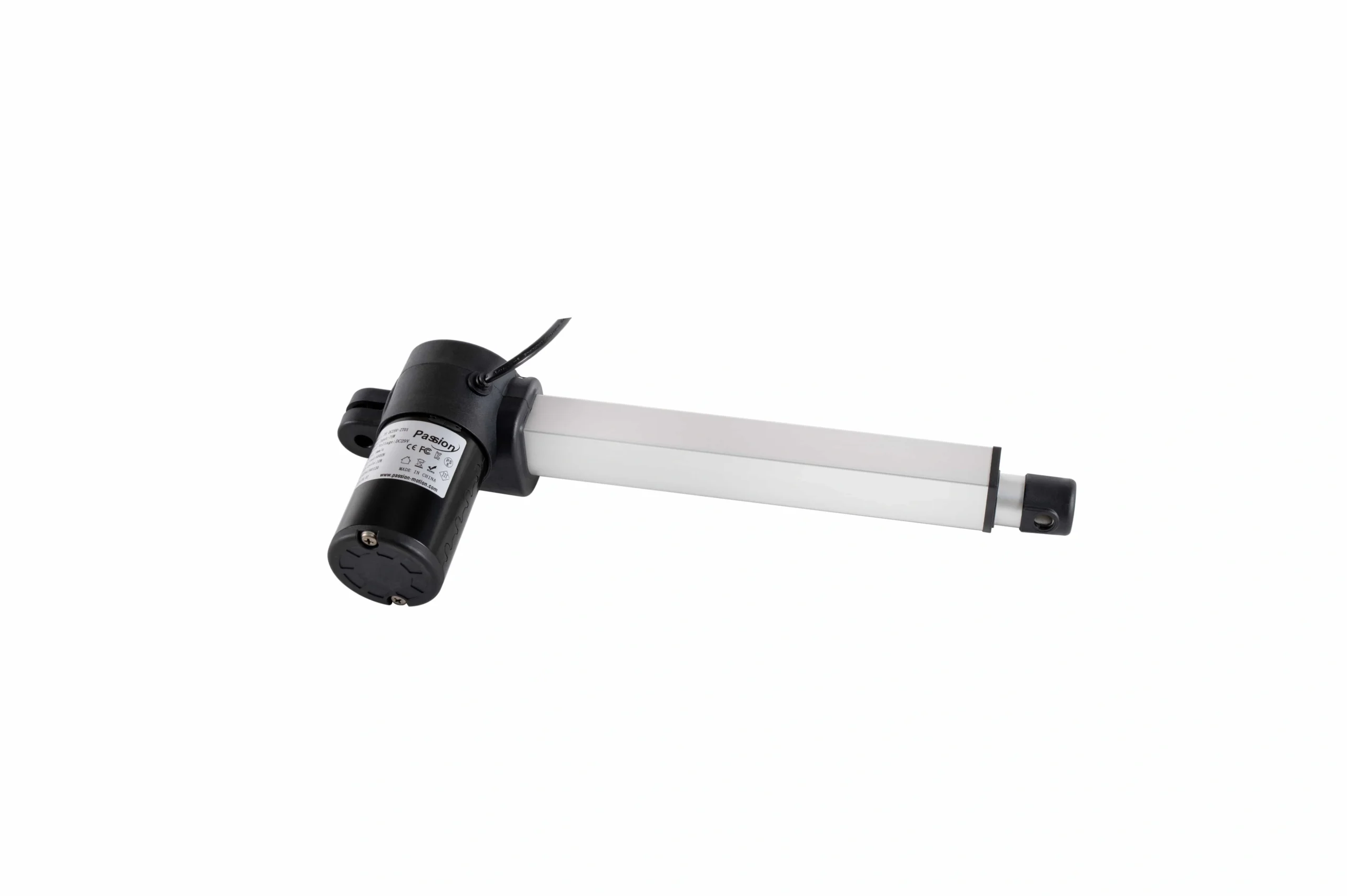
The actuator, feedback method, drive stage, and control logic form one engineering loop.
TiMOTION's feedback overview and Progressive Automations' control-system guide both illustrate why feedback technology changes what the control system can measure and regulate. For an OEM project, that means feedback belongs in the system-interface specification, not as an afterthought.
Single-axis and multi-axis control
When more than one actuator is used, the phrase “move together” can describe several different architectures.
Independent channels
Each axis receives its own commands and can stop, fault, or move separately.
Ganged command
Two or more axes receive the same motion command, but the system does not necessarily compare their positions.
Master/follower
One axis becomes the reference and another follows its measured position or speed.
Cross-coupled synchronization
The controller compares axes and actively corrects differential position error.
Coordinated trajectory
Multiple axes follow a common time-based profile, often with coordinated acceleration and deceleration.
The important distinction is that simultaneously energizing motors is not the same as synchronization . Friction, loading, transmission efficiency, supply voltage, and tolerances can cause two motors to travel differently even when they receive the same command.
For a commercial project that requires multi-axis coordination, see ServoCylMotion's multi-motor synchronization capability .
Wired, wireless, PLC, and network interfaces
Communication is another layer that should be selected from the application requirement backward.
Discrete I/O
Useful for simple signals such as:
- enable;
- extend/retract;
- home;
- limit;
- ready;
- fault.
Analog commands
Analog voltage or current signals can be used for proportional speed, force, or position commands when noise, update rate, and scaling are acceptable.
Serial and fieldbus communication
A networked implementation may define:
- physical layer;
- protocol;
- cyclic update rate;
- command acknowledgment;
- heartbeat/watchdog;
- communication-loss behavior;
- diagnostics;
- parameter access;
- version management.
Industrial systems may use RS-485, CAN, Ethernet-based networks, or standardized motion profiles depending on the control platform.
Wireless command
Wireless control can be practical when physical cabling is inconvenient, but the design should explicitly define:
- pairing;
- command authority;
- timeout;
- lost-packet behavior;
- low-battery behavior;
- interference response;
- whether local fallback control exists.
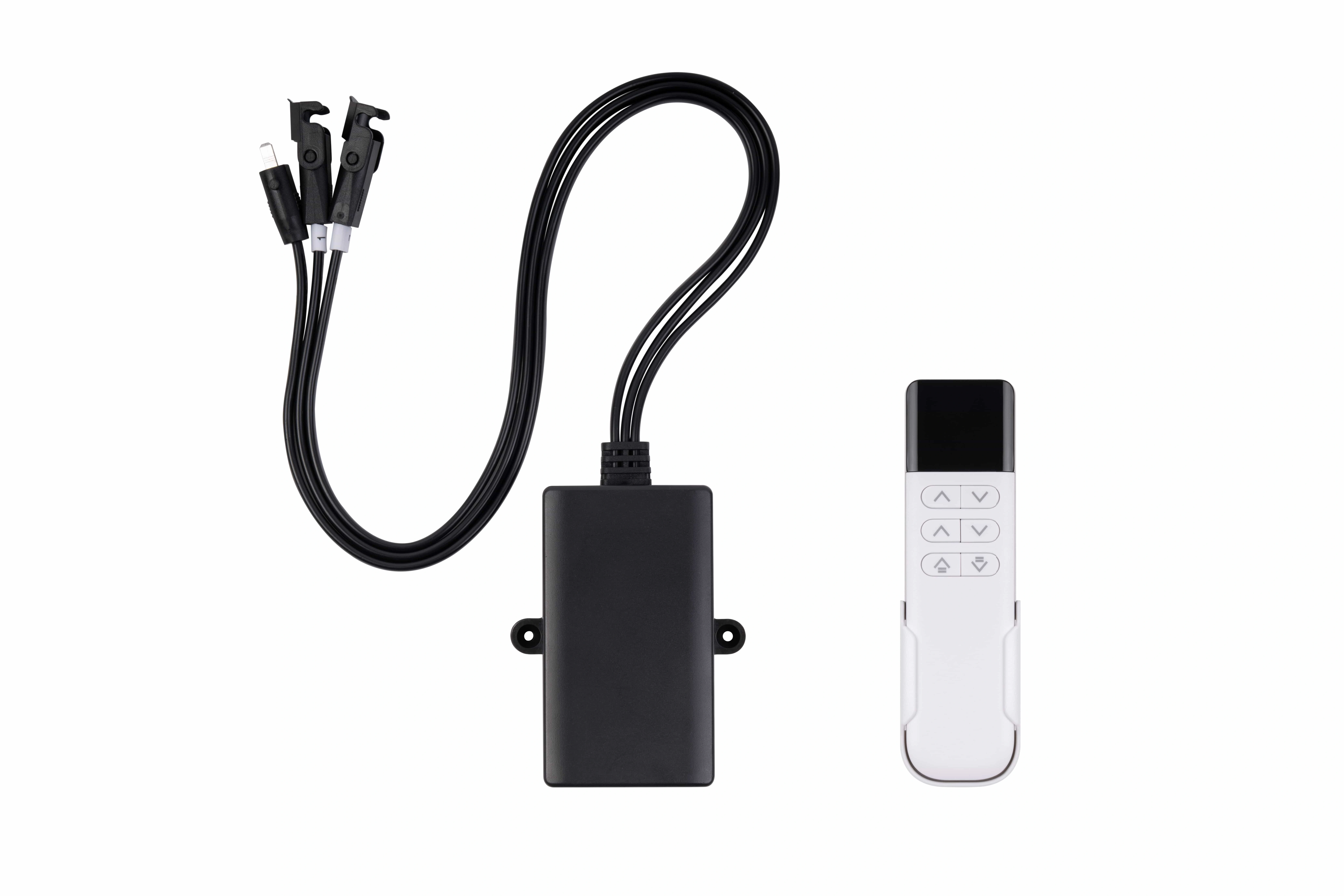
Wireless control is a command transport choice; loss behavior and safety requirements must be defined separately.
For available commercial wireless-control hardware, use the wireless motor controls page . The engineering article stays focused on architecture rather than product selection.
Wireless command should not be assumed to satisfy a machine safety function. Safety behavior requires its own engineered and validated architecture.
Protection and fault handling
Protection logic should be defined separately from normal motion logic.
Potential conditions include:
- overcurrent;
- short circuit;
- stall;
- obstruction;
- overtemperature;
- under- or overvoltage;
- feedback loss;
- communication loss;
- positive or negative overtravel;
- brake fault;
- controller restart.
For each condition, define the expected response:
- immediate disable;
- controlled stop;
- reverse-away recovery;
- status-only warning;
- latched fault;
- automatic retry;
- manual reset.
A useful requirements sheet also defines whether a fault on one axis stops all axes or only the affected channel.
Reset, homing, and commissioning are part of the architecture
Commissioning logic should not be left until installation.
The OEM team should decide:
- whether position is known at power-up;
- whether the axis must establish a reference;
- which sensor or datum defines home;
- allowed homing direction and speed;
- whether a backoff-and-reapproach sequence is required;
- whether automatic motion is blocked until homing completes;
- how a reset differs from clearing a fault;
- what happens after loss of feedback or power.
Those details are covered more deeply in the dedicated reset/homing spoke, but the pillar should still identify them as required architecture inputs.
OEM control-requirements checklist
Before selecting control hardware, freeze these inputs.
Motion behavior
- number of axes;
- independent or coordinated operation;
- stroke and speed profile;
- positioning requirement;
- acceptable following error;
- stop behavior;
- braking/holding requirement.
Command layer
- manual, PLC, HMI, remote, or network source;
- command priority;
- manual/automatic/service modes;
- local override rules.
Drive and power
- motor type;
- supply architecture;
- continuous and peak current;
- simultaneous-motion case;
- braking/coasting behavior;
- current limiting;
- power-distribution and wiring constraints.
Feedback
- sensor type;
- signal interface;
- scaling/resolution;
- direction convention;
- reference/homing requirement;
- loss-of-feedback response.
Multi-axis behavior
- channel count;
- channel mapping;
- independent, master/follower, or synchronized mode;
- axis-to-axis tolerance;
- fault behavior if one axis falls behind.
Communication
- discrete, analog, serial, fieldbus, or wireless;
- protocol;
- update rate;
- watchdog;
- communication-loss behavior.
Protection and commissioning
- limits and overtravel;
- stall/obstruction detection;
- thermal and current protection;
- emergency-stop interface;
- reset behavior;
- homing behavior;
- fault logging;
- firmware/parameter revision.
Once these inputs are defined, the project can move to system compatibility review without relying on connector appearance or product labels as proof of fit.
If you already have a draft I/O list, motion sequence, or control requirements sheet, send it through ServoCylMotion contact for a project-specific review.
FAQs
What are the main layers of an actuator control system?
A useful architecture separates command/user interface, supervisory logic, drive/power, actuator/motor, feedback/protection, communication, and commissioning/state behavior. Some products integrate several layers, but the engineering interfaces still need to be defined.
When is open-loop control sufficient?
Open-loop control can be sufficient when approximate end-to-end motion is acceptable and the system does not need to verify intermediate position or correct motion disturbances. Requirements for precision, presets, synchronization, or diagnostics usually push the architecture toward measured feedback.
What changes when position feedback is added?
The system can compare commanded and actual motion. Depending on the sensor and control logic, that can support intermediate positioning, speed calculation, error correction, synchronization, diagnostics, and more controlled fault detection.
Is sending the same command to two motors the same as synchronization?
No. Two motors can drift under different loads or friction even when they receive the same command. Synchronization requires suitable feedback and logic that measures and corrects differential motion.
Why does feedback compatibility matter?
The control logic must understand the sensor's electrical interface, signal type, scaling, direction convention, and fault behavior. A mechanically compatible actuator is not necessarily control-compatible if its feedback scheme differs.
How should wireless control fit into the architecture?
Treat wireless as a command-transport layer. Define pairing, command authority, timeout, interference/loss behavior, and fallback operation. Keep machine-safety requirements separate unless a complete wireless safety function is specifically engineered and validated.
What should be frozen before choosing control hardware?
Freeze the motion objective, axis count, command sources, power budget, motor/drive interface, feedback type, communication method, multi-axis topology, protection behavior, and reset/homing requirements first.
