

Linear Actuator Reset and Homing: Safe Troubleshooting and Reference Recovery

“Reset” and “homing” are often used as if they mean the same thing. In motion control, they usually do not.
A reset may clear a fault, restart electronics, or return a controller to a defined state. Homing establishes a known mechanical or feedback reference so that the control system can interpret position correctly.
That difference matters during troubleshooting. Clearing a fault does not prove that the axis knows where it is, and running a homing move does not fix a damaged cable, incorrect limit input, jammed mechanism, or missing feedback signal.
Generic rule: verify the hardware and reference architecture first, then follow the exact model-specific recovery procedure from the verified manual.
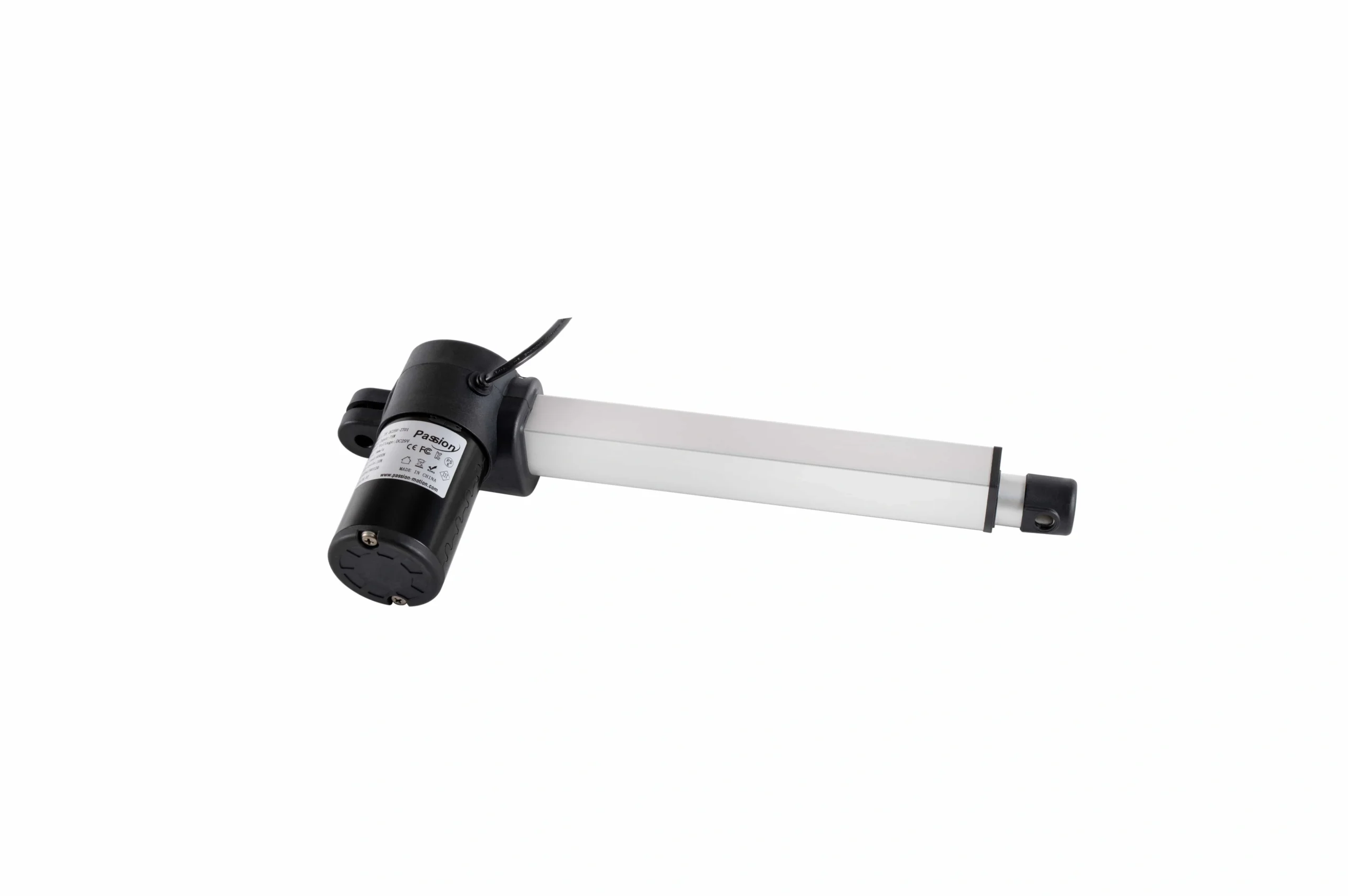
A controller reset changes system state; homing establishes or verifies the axis reference used for position control.
Reset, initialization, homing, and calibration are different
| Term | Main purpose | Does it move the axis? | Typical reason |
|---|---|---|---|
| Fault clear / reset | clear a latched controller state | not necessarily | recover after a resolved fault |
| Controller restart | reboot electronics and logic | normally no | recover from software/state issue |
| Initialization | establish usable internal state | may or may not | startup or configuration change |
| Homing / referencing | establish known axis position | usually yes | incremental position was unknown or reference required |
| Calibration | align measured values with physical reality | may require motion | setup, service, replacement or drift correction |
A project-specific manual may use these words differently, so always verify the actual terminology before issuing commands.
Does every electric actuator need homing?
No.
Whether homing is required depends on the feedback architecture and how position is retained.
Incremental feedback
Hall pulses or incremental encoders typically tell the system how far the motor has moved relative to a previous reference. If the controller loses the accumulated position—after power loss, disconnection, certain faults, or configuration changes—it may need to establish a reference again.
IAI, Ultra Motion, Rockwell Automation, and Advanced Motion Controls all document homing concepts built around establishing or restoring that reference.
Absolute feedback
An absolute-position device can report position without reconstructing it only from accumulated pulses. Depending on the complete architecture, routine homing after every power cycle may not be required.
That does not mean an absolute system never needs calibration, verification, or recovery. It only changes how the controller knows position.
Generic diagnostic flow before attempting homing
This is the safest useful answer for an unknown actuator system because it avoids inventing a button sequence.
Step 1: identify the exact system
Record:
- actuator or axis model;
- controller/control unit model;
- feedback type;
- command interface;
- power source;
- software/firmware revision if relevant;
- current fault or symptom.
Do not apply a recovery sequence from a visually similar product.
Step 2: make the mechanism safe to move
Before commanding motion:
- remove unexpected loads where possible;
- make sure people and tools are clear;
- confirm the mechanism can travel without collision;
- verify guards/interlocks required by the machine;
- identify any rigid multi-axis coupling.
A homing routine may intentionally move toward a switch or reference point. The path must be known and clear.
Step 3: verify power and wiring
Check:
- supply is present;
- correct voltage range for the actual system;
- fuses/protection are not open;
- motor connector is fully seated;
- feedback connector is seated;
- limit/home inputs are connected as designed;
- cables are not visibly damaged or pinched.
A reset cannot solve a disconnected feedback cable.
Step 4: verify limit and home states
A controller may refuse to home if it sees:
- both limits active;
- an unexpected home-switch state;
- an overtravel input;
- an interlock;
- a polarity/direction mismatch.
Confirm the actual input status using the approved service method.
Step 5: clear the fault only after the cause is understood
If the system reports a fault, first determine whether the condition still exists.
Examples include:
- overcurrent;
- feedback loss;
- overtravel;
- communication loss;
- thermal fault;
- obstruction;
- following error.
Clearing a fault repeatedly without correcting the cause can turn a diagnostic problem into a mechanical one.
Step 6: execute the verified homing/reference method
Use the documented method for the actual axis.
A homing routine can involve:
- moving toward a home switch;
- finding a limit and backing away;
- detecting an encoder index;
- approaching a reference in two stages;
- applying a home offset;
- in some purpose-designed systems, controlled hard-stop detection.
Do not invent direction, speed, current limit, button hold time, or backoff distance.
Step 7: confirm direction and reference
After homing:
- verify displayed/reported position;
- jog a small safe distance;
- confirm positive/negative direction;
- confirm limits act in the correct direction;
- check feedback counts or position changes logically.
Step 8: validate full intended travel
Only after the reference is credible should the machine perform a controlled travel verification.
Check:
- no binding;
- limits work;
- feedback remains valid;
- position is repeatable enough for the application;
- multi-axis systems remain within their allowed relationship.
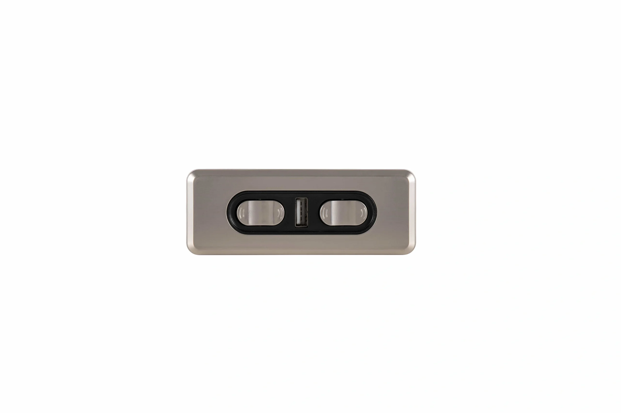
Command-interface behavior is model-specific; the verified manual must define any actual reset or reference sequence.
Common homing methods
Home switch
A dedicated reference switch gives the controller a repeatable physical event.
A common sequence is conceptually:
- move toward the expected home region;
- detect the switch;
- move off it;
- approach again in a defined direction/speed;
- set the reference plus any configured offset.
The exact sequence varies.
Limit-switch referencing
Some systems use a travel limit as the reference event. The controller may approach the limit, detect it, back off, and assign a coordinate.
The limit still has to be distinguished from independent overtravel protection.
Encoder index
An incremental encoder can provide a precise index event. The axis may first find a coarse switch, then move until the index pulse establishes the final reference.
Controlled hard-stop homing
Some systems are intentionally designed to move gently into a known mechanical stop and detect the event from current or following error.
That method should never be assumed safe for an unknown mechanism. It requires a drive, structure, load, speed, and current strategy specifically designed for it.
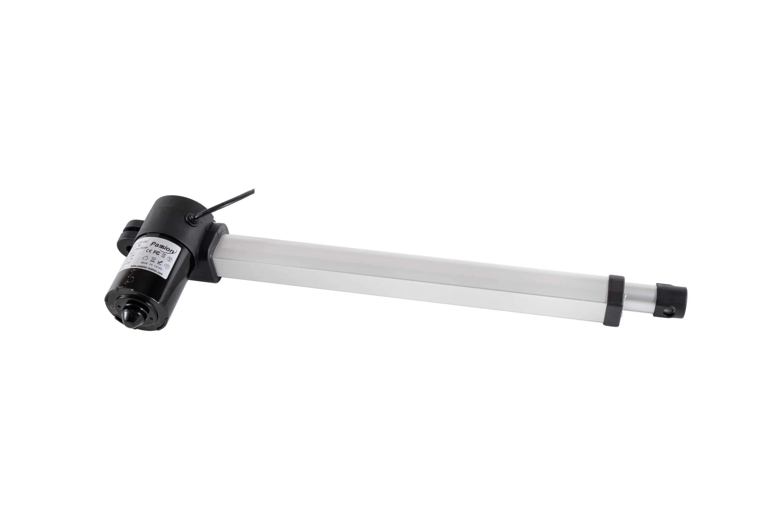
Reference methods depend on the feedback and limit architecture, not on actuator appearance alone.
Why an axis can home in the wrong direction
Common causes include:
- configured home direction is wrong;
- motor polarity changed;
- feedback direction is inverted;
- home switch starts in the unexpected state;
- channel mapping is wrong;
- limit inputs are swapped;
- software coordinate sign is reversed.
Do not compensate by swapping wires blindly. First identify which convention is wrong.
Reset problems that are not really reset problems
The actuator does not move at all
Check power, fuse, command input, motor output, connectors, interlocks, and mechanical binding before assuming reset is required.
It moves in one direction only
Possible causes include:
- end-limit state;
- command input issue;
- relay/drive fault;
- wiring damage;
- mechanical jam.
Position is wrong after power-up
Investigate whether the system uses incremental feedback and lost its reference.
Position drifts over repeated cycles
Check for:
- missed feedback pulses;
- sensor noise;
- mechanical backlash;
- loose couplings;
- calibration/reference error;
- inappropriate homing method.
It faults during homing
Possible areas to inspect include:
- obstruction;
- wrong home direction;
- unexpected limit state;
- feedback not changing;
- current/torque too high;
- axis mismatch in multi-axis equipment.
Multi-axis recovery needs extra care
If two or more actuators move one rigid load, do not treat each channel as an isolated axis unless the mechanical design allows it.
Before recovery, verify:
- which actuator belongs to each channel;
- current physical skew;
- feedback state on each axis;
- whether individual jogging is allowed;
- whether the system requires coordinated referencing;
- what happens if one axis reaches home first.
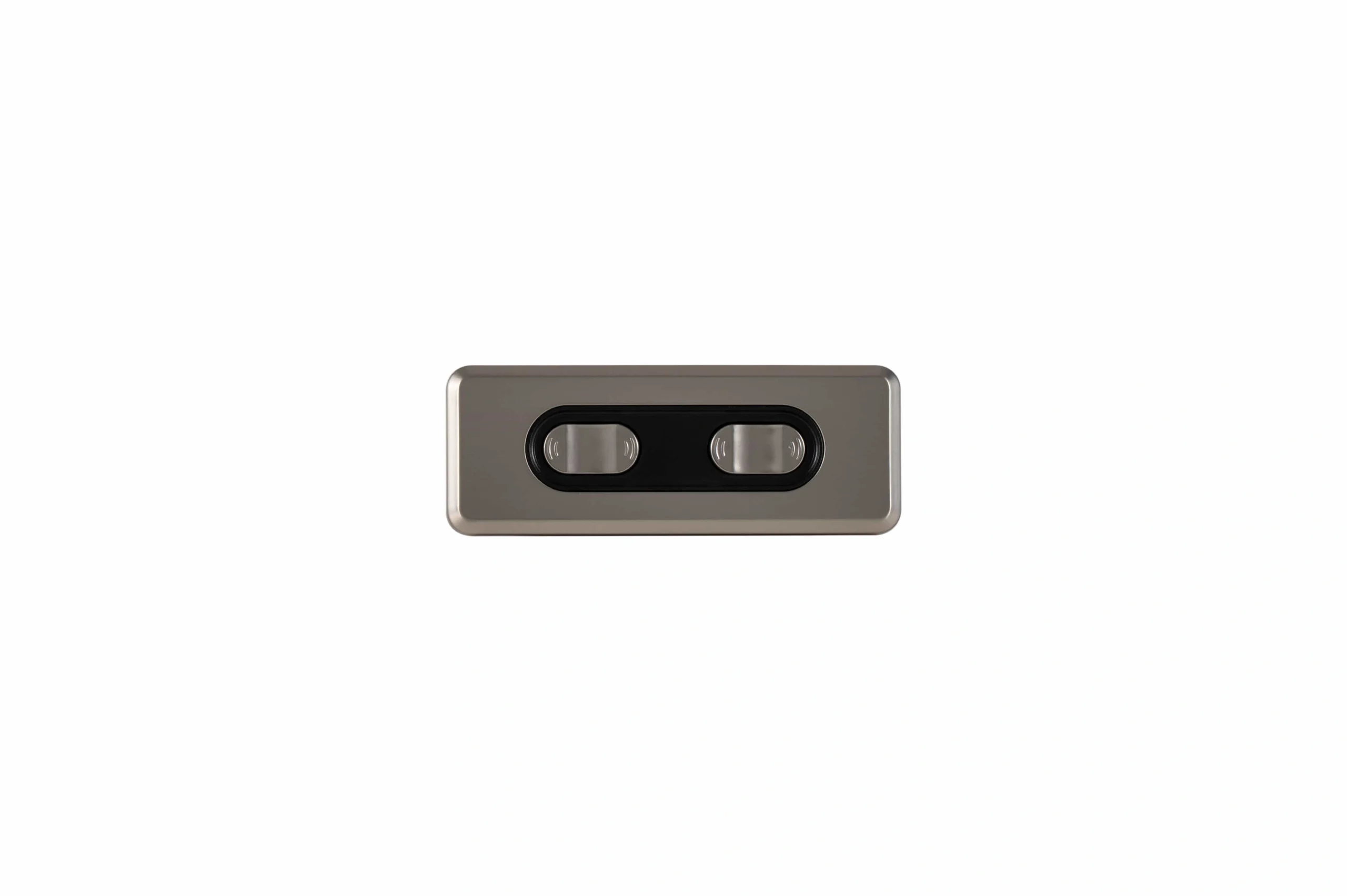
In multi-axis systems, channel mapping and feedback state should be verified before any coordinated recovery move.
A recovery move that is harmless on a single axis can rack a shared structure if only one side moves.
For mixed controllers, feedback, power, or actuator interfaces, use the system compatibility resource before attempting a recovery based on assumptions.
Troubleshooting table
| Symptom | First checks | Do not assume |
|---|---|---|
| No motion after reset | power, enable, fault, motor wiring, obstruction | that reset should cause movement |
| Axis reports unknown position | feedback type, retained position, reference state | that power cycling restores position |
| Homes in wrong direction | configuration, polarity, feedback direction, switch state | that swapping motor wires alone fixes it |
| Stops before home | limit input, obstruction, current/fault, switch state | that the axis needs more force |
| Reaches home but position is inconsistent | sensor repeatability, backoff/approach, mechanics, scaling | that software offset is the only issue |
| Multi-axis system skews | channel map, feedback, mechanical load, coordinated mode | that both motors received equal commands |
Commissioning record
After a successful reference recovery, record:
- homing method;
- reference device;
- direction;
- home offset;
- software/parameter revision;
- observed limit states;
- successful travel verification;
- any fault that triggered the recovery;
- corrective action.
This makes the next fault easier to diagnose and prevents an undocumented workaround from becoming the de facto production process.
If the exact manual or controlled drawing is missing, use ServoCylMotion’s technical documentation resource or contact the engineering team before improvising a reset sequence.
FAQs
What is the difference between resetting and homing an actuator?
Resetting changes controller or fault state. Homing establishes a known position reference. One does not automatically perform the other.
Does every actuator need homing after power-up?
No. It depends on the feedback and position-retention architecture. Incremental systems commonly need a reference when position is lost; absolute systems may retain or report position directly.
What should I check before homing?
Verify the exact model/manual, clear the travel path, confirm power, motor and feedback wiring, inspect limit/home states, and resolve active faults first.
Can a mechanical end stop be used as home?
Only if the system is specifically designed for controlled hard-stop homing. Do not drive an unknown actuator into a stop as a generic recovery method.
Why does my axis home in the wrong direction?
Possible causes include wrong home-direction configuration, swapped motor polarity, inverted feedback direction, incorrect switch logic, or wrong channel mapping.
Should a reset automatically restart motion?
It should not be assumed. Restart behavior is part of the specific control architecture and machine risk assessment. Follow the verified manual and commissioning rules.
