Linear Actuators for TV Lifts: OEM Selection Guide
Select linear actuators for TV lifts by moving load, stroke, cabinet space, holding, speed, noise, controls, power, cable routing, and validation.

Choosing linear actuators for TV lifts is primarily a geometry and load-definition problem, not a product-name problem.
An AV lift assembly has to move more than the display itself. It may also move a mounting plate, guide carriage, decorative lid, cable carrier, brackets, and other structure. The actuator must fit inside the enclosure when retracted, provide enough travel to reach the viewing position, hold the assembly safely when stopped, and work with the required controls and power architecture.
For OEM work, the best selection sequence is:
- define the total moving load and load path;
- derive the required travel from actual hidden and visible positions;
- verify retracted length and cabinet clearance;
- define speed, noise, duty cycle, and power-off behavior;
- decide whether one or two axes are required;
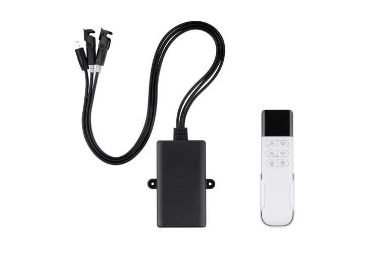
- specify limits, feedback, controls, and power;
- validate the complete assembly under worst-case conditions.
Table of Contents
TV lift actuator selection table
| Requirement | What to define | Why it matters |
|---|---|---|
| Total moving load | display, bracket, moving carriage, lid/panel, cables, added hardware | screen weight alone can understate required force |
| Load direction | vertical rise, vertical descent, assisted or counterbalanced motion | gravity changes force and holding behavior |
| Stroke | travel from concealed to viewing position plus required margin | insufficient travel prevents full motion |
| Retracted length | available space in the hidden position | long body length can conflict with cabinet depth/height |
| Mounting geometry | fixed and moving pivot points, bracket stiffness, guide alignment | poor geometry can introduce binding or side load |
| Speed | target rise/lower time | affects user experience, current, noise, and cycle time |
| Noise | acceptable acoustic behavior in the final enclosure | cabinet panels can amplify vibration or gear noise |
| Holding / backdrive | required position stability with power removed | vertical assemblies may need self-locking or braking behavior |
| Duty cycle | moves per hour and rest time | repeated cycles create thermal load |
| End limits | upper/lower stop method | prevents overtravel and protects the structure |
| Feedback | end-only, presets, continuous position, diagnostics | determines control sophistication |
| Axis count | one actuator or two coordinated axes | wide/heavy structures may need different architecture |
| Power | supply range, continuous/peak current, cable drop | a mechanically suitable actuator can still be electrically mismatched |
| Cable routing | moving loops, connector clearance, pinch protection | cables must survive the full travel |
| Validation | full-load, alignment, limits, noise, cycles, power-off state | proves the actual assembly rather than the bench setup |
AV lift selection should verify total moving load, travel, retracted length, mounting, and control requirements together.
The table is intentionally application-focused. It does not say that one actuator family is universally suitable for AV equipment.
Start with the total moving load
The first requirement is not “TV weight.” It is everything the actuator must move .
Include:
- display;
- VESA or custom mounting plate;
- moving frame;
- guide carriage;
- decorative panel or lid if it moves;
- cable carrier;
- brackets;
- attached accessories;
- any counterbalance force;
- guide friction.
Then identify the load direction and center of gravity.
A screen mounted close to a well-guided vertical carriage is different from a wide assembly with an offset center of gravity. The second design can create a larger moment on the frame and increase guide friction even if the total mass is similar.
Use the actuator sizing resource after the load path is defined to calculate the required force and design margin.
Do not let the actuator become the guide
The linear motion device should usually be treated as the source of axial force, while the mechanical frame manages lateral loads and moments.
Check:
- guide parallelism;
- guide stiffness;
- bracket deflection;
- center-of-gravity offset;
- side-load path;
- cable drag;
- lid linkage forces;
- tolerance stack.
A stronger actuator does not solve a binding guide system.
Derive stroke from the actual display positions
Stroke should be calculated from the geometry of the hidden and viewing positions.
Measure:
- lower concealed position;
- upper viewing position;
- required screen clearance;
- bracket offsets;
- guide-carriage travel;
- any lid-opening linkage travel;
- mechanical stop locations.
The actuator's required travel may differ from the visible screen movement if the mechanism uses levers, offset mounts, or a moving lid.
Always validate the kinematic relationship in CAD or a physical mock-up.
Add margin carefully
A small travel margin can help tolerate manufacturing variation, but excess stroke is not automatically harmless. If the actuator can drive farther than the structure allows, the design needs end-limit logic or mechanical protection to prevent overtravel.
Retracted length can decide whether the design fits
For concealed displays, the most important dimension may be the closed installation envelope .
The selection sheet should include:
- retracted body length;
- mounting-center distance;
- motor housing dimensions;
- connector location;
- cable exit direction;
- bracket thickness;
- cabinet internal height/depth;
- service removal clearance.
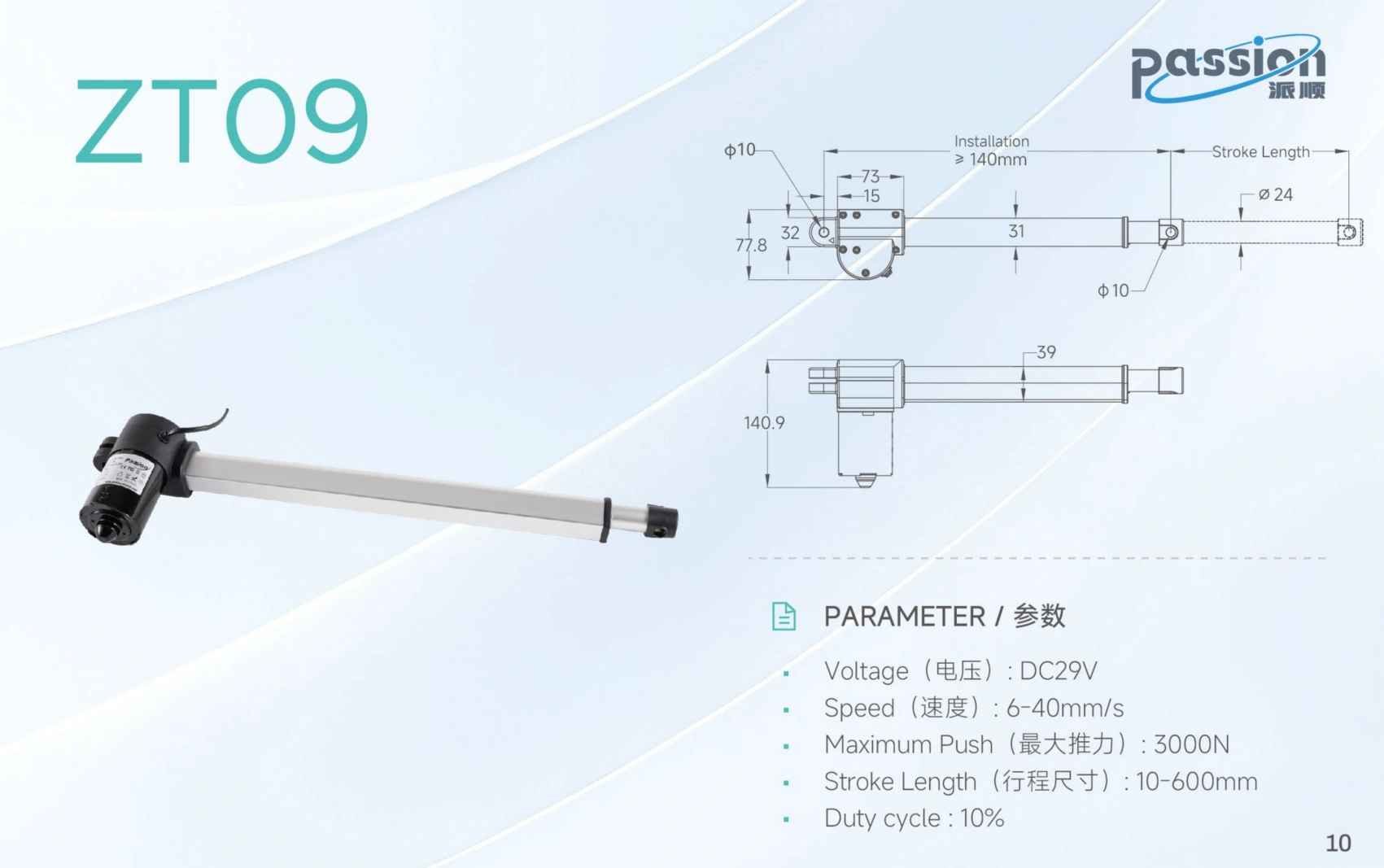
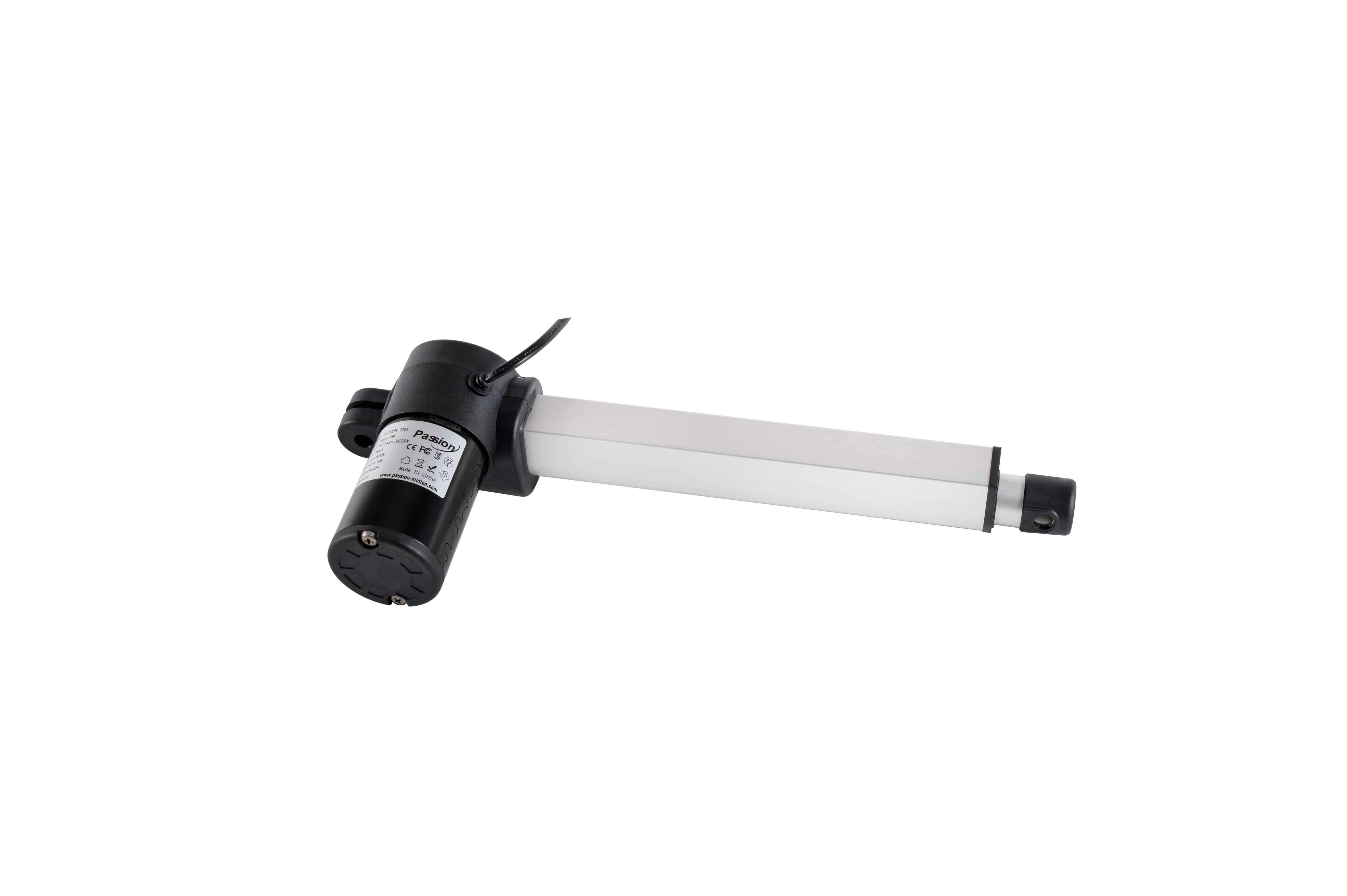
Similar stroke does not guarantee similar installation envelope, connector clearance, or mounting geometry.
Two actuators with the same stroke can require very different cabinet space.
This is why model selection should happen after the enclosure geometry is known rather than before furniture design is frozen.
Pop-up and drop-down arrangements change the engineering problem
A pop-up assembly rises from furniture or a cabinet. A drop-down assembly lowers from a ceiling, overhead enclosure, or upper structure.
Both require controlled linear motion, but gravity acts differently relative to the intended direction.
Pop-up arrangement
Typical engineering questions:
- What force is needed to lift the complete moving mass?
- How is the assembly held at the viewing position?
- Can the load backdrive when power is removed?
- Does the lid add force near the start of travel?
- What prevents the carriage from twisting?
Drop-down arrangement
Typical questions:
- How is the load supported when stored overhead?
- What happens if power is removed during travel?
- Is controlled lowering required?
- What secondary restraint or brake logic is part of the machine risk assessment?
- How is cable routing handled through the moving path?
The right choice depends on the full mechanical and safety architecture. The dedicated AV lift solution page owns the commercial solution context after the selection inputs are defined.
Define holding and power-off behavior explicitly
Vertical motion requires a clear answer to: what happens when power is removed?
Possible requirements include:
- maintain position mechanically;
- maintain position with a brake;
- allow controlled descent;
- return to a safe position;
- prevent movement until power is restored.
Do not infer holding behavior from moving force alone.
A system can have enough force to raise the display and still be unsuitable if it backdrives under load or if its stopping behavior is inconsistent with the enclosure design.
The requirement sheet should separate:
- dynamic lifting force;
- static holding requirement;
- power-off behavior;
- brake or self-locking requirement;
- emergency/fault state.
Speed and noise should be specified together
AV equipment is usually used in occupied spaces. Motion quality matters.
Define:
- target travel time;
- acceleration/deceleration behavior;
- acceptable startup shock;
- acceptable stop shock;
- acoustic target;
- whether motion occurs during meetings, hospitality use, or residential use.
A faster lift may create more noise, higher peak current, and a harsher stop. A slower lift may feel more refined but increase cycle time.
The correct compromise should be tested in the final enclosure because cabinet panels can amplify vibration or change perceived sound.
Duty cycle: how often will the display move?
Many AV lift assemblies operate intermittently, but OEM designs should still define:
- expected moves per hour;
- maximum repeated cycles;
- run time per cycle;
- rest time;
- ambient temperature;
- enclosure ventilation;
- maximum moving load during repeated operation.
A showroom demonstration of a few cycles does not prove thermal suitability for a hospitality, conference, marine, or automation installation that cycles more often.
One actuator or two?
A single actuator can simplify control and eliminate synchronization between axes.
Two actuators may be considered when:
- the moving structure is very wide;
- load distribution makes one central drive difficult;
- the frame architecture uses two lifting points;
- structural stiffness requires distributed force.
If two axes are used, define:
- controller channel count;
- feedback type on both axes;
- allowed position mismatch;
- stop behavior if one axis faults;
- initialization/reset behavior;
- load balance.
Sending the same command to two motors is not sufficient proof that they will stay level. For projects requiring coordinated axes, review the multi-motor synchronization capability .
Limits, feedback, presets, and user controls
The required control architecture depends on what the user expects.
End-position-only operation
A basic system may only need upper and lower end limits.
Preset or repeatable positions
If the display must stop at repeatable intermediate positions, the control system needs position information and a defined reference.
Diagnostics and safer fault handling
Feedback can also support:
- motion verification;
- speed comparison;
- stalled-axis detection;
- synchronization;
- service diagnostics.
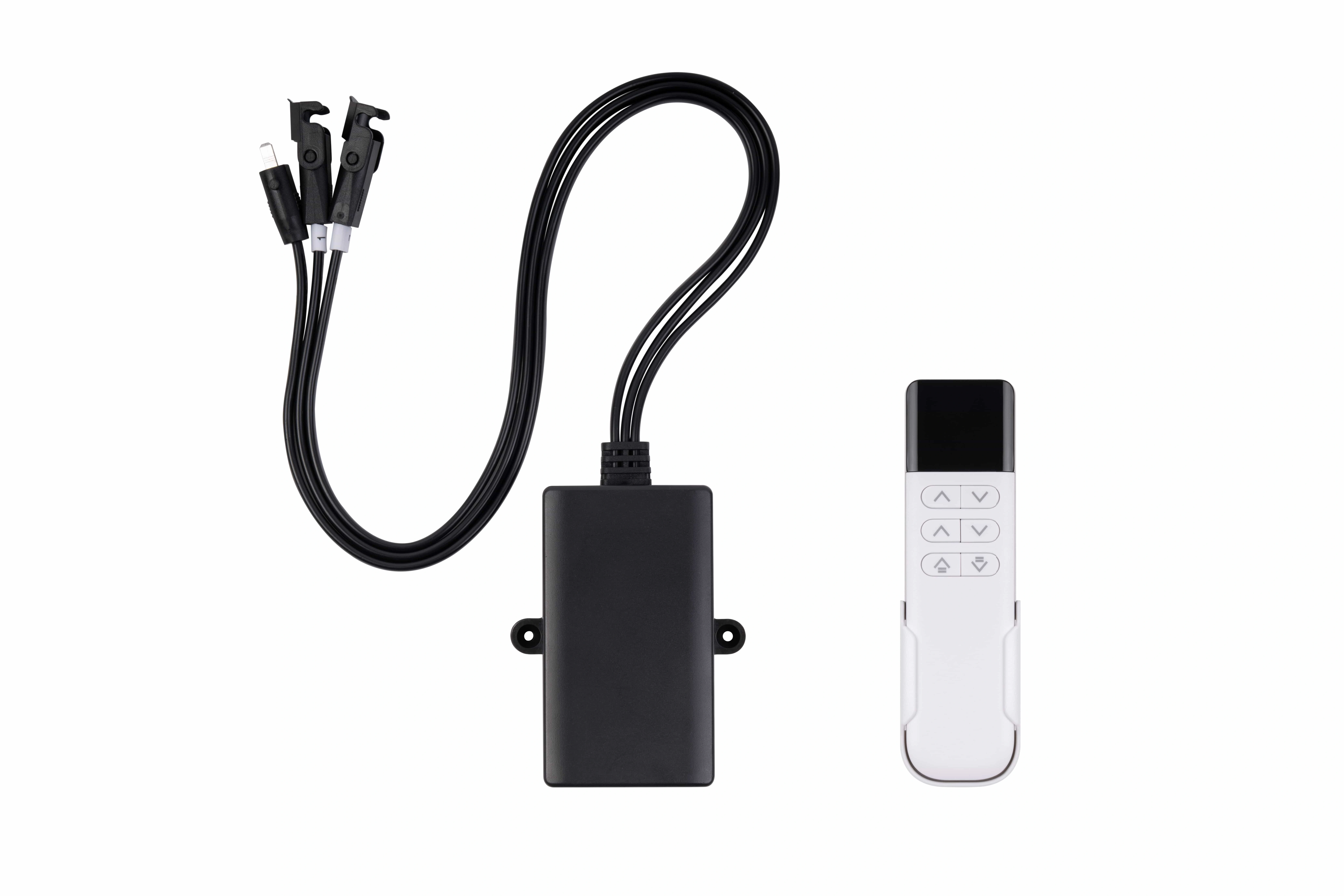
Remote command is only one layer; limits, feedback, channel count, and fault behavior still need to be defined.
Possible user interfaces include local buttons, wired handsets, wireless remotes, or a supervisory automation system. The interface should be chosen after the command, feedback, and fault requirements are defined.
Power and cable routing belong in the mechanical design
Do not wait until final assembly to route the power and control wiring.
Define:
- supply voltage range;
- continuous current;
- peak/start current;
- connector orientation;
- cable length;
- conductor size;
- moving service loop;
- bend radius;
- strain relief;
- pinch protection;
- separation from sharp edges.
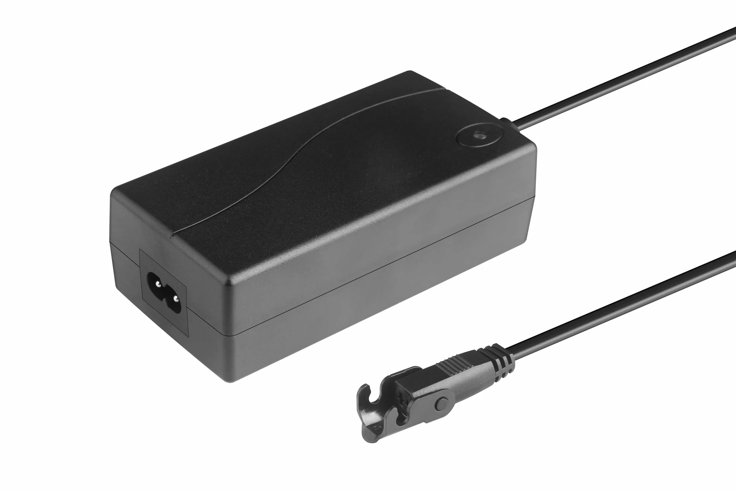
Power, peak current, cable length, and connector routing should be validated in the final cabinet configuration.
A cable that is electrically correct but too short, too stiff, or poorly routed can fail in a moving cabinet.
For a project with known actuator, control, and supply candidates, use the system compatibility resource to verify the electrical interfaces together.
Obstruction and pinch-point review
A moving display can create pinch points at:
- cabinet openings;
- lid edges;
- guide rails;
- bracket interfaces;
- ceiling openings;
- cable paths.
The machine-level design should define:
- physical guards;
- current/force sensing where applicable;
- obstruction response;
- stop/reverse behavior;
- user warnings;
- maintenance lockout;
- fault reset.
Do not assume that ordinary end limits provide full obstruction protection.
Prototype validation checklist
Before releasing the AV lift assembly, validate the exact production-intent configuration.
Mechanical
- full moving load;
- center of gravity;
- complete stroke;
- hidden and viewing clearances;
- guide alignment;
- bracket deflection;
- lid linkage;
- cable drag.
Motion
- rise/lower time;
- acceleration/deceleration;
- stop behavior;
- repeated cycles;
- noise in the finished enclosure;
- position repeatability if required.
Controls
- upper/lower limits;
- presets if used;
- remote/local control priority;
- feedback loss;
- one-axis fault behavior in dual-axis systems;
- reset/recovery behavior.
Power
- worst-case current;
- supply voltage at the load;
- cable voltage drop;
- connector temperature;
- power-off holding behavior.
Service
- access to actuator and controller;
- cable replacement;
- mounting fasteners;
- safe manual recovery if required.
If these requirements are already defined, send the selection sheet through ServoCylMotion contact for project-specific review.
FAQs
What load should be used when selecting an actuator for a TV lift?
Use the full moving load, not only the screen. Include the mounting plate, moving frame, cabinet lid if applicable, cables, brackets, and guide friction.
How do I determine the required stroke?
Measure the mechanism travel between the fully concealed and viewing positions, including bracket geometry and any linkage effects. Confirm the relationship in CAD or a physical mock-up.
Why is retracted length important?
Because the actuator must fit inside the enclosure in the hidden position. Body length, motor housing, connectors, and mounting-center distance can all affect fit.
Is low noise a valid selection requirement?
Yes. Define an acoustic target and validate the finished enclosure, because furniture panels and mounting structures can amplify vibration.
When should two actuators be used?
Only when the mechanical architecture justifies multiple lifting points. If two axes are used, define feedback and synchronization requirements rather than assuming identical commands will keep them level.
What should happen when power is removed?
That is a design requirement. The assembly may need to hold position, brake, descend in a controlled way, or move to another safe state depending on the machine architecture.