Types of Linear Actuators: A Practical Engineering Classification
Compare types of linear actuators by power source, drive mechanism, architecture, force, speed, stroke, control, duty cycle, and environment.

The main types of linear actuators can be grouped first by the energy that creates motion—motor-driven electromechanical, pneumatic, hydraulic, mechanical/manual, and specialized direct-actuation technologies. Within those families, engineers can classify the mechanism again by screw, belt, rack-and-pinion, direct linear drive, or another motion-conversion method. Rod, rodless, slider, and lifting-column designs describe physical architecture, not the same classification level.
That distinction matters because two devices can both produce straight-line motion while behaving very differently in force, speed, stroke, positioning, duty cycle, control, installation space, and maintenance.
Table of Contents
The Three Classification Layers to Keep Separate
A practical actuator taxonomy answers three different questions:
- What energy source creates the force? This separates motor-driven systems from pneumatic, hydraulic, manual, and specialized technologies.
- How is that energy converted into linear travel? A motor-driven system may use a screw, belt, rack-and-pinion transmission, or a direct linear motor.
- How is the moving element packaged and guided? The product may use an extending rod, a carriage on a track, a guided slider, or a telescoping column.
Many lists of linear actuator types mix these layers. For example, “pneumatic,” “ball screw,” and “rodless” can all be valid descriptions, but they answer three different engineering questions.
Product form factor is one classification dimension; the underlying power source and motion-conversion mechanism are separate questions.
Once the layers are separated, comparisons become more useful. The buyer can first choose a plausible technology family, then evaluate the mechanism and architecture that fit the machine.
Main Linear Actuator Technology Families Compared
The table below is a starting framework, not a universal performance ranking. Actual capability depends on design details, operating point, guidance, controls, and the surrounding system.
| Technology family | How linear motion is produced | Often considered when | Key engineering checks |
|---|---|---|---|
| Motor-driven electromechanical | A motor drives a screw, belt, rack-and-pinion transmission, or another linear-motion mechanism | Programmable positioning, controlled motion profiles, integration with electronic controls, or clean self-contained equipment are important | Required force, speed, stroke, duty cycle, motor/drive sizing, feedback, thermal limits, holding behavior, guidance |
| Pneumatic | Compressed air acts on a piston or carriage | Fast repetitive motion, simple end-to-end moves, and existing plant air make the system practical | Air supply quality, pressure stability, valves, cushioning, positioning requirement, noise, leakage, cycle rate |
| Hydraulic | Pressurized liquid acts on a piston | High force density, shock tolerance, or heavy machinery requirements justify fluid-power infrastructure | Power unit, pressure/flow, seals, hoses, fluid condition, leakage control, maintenance, temperature, positioning |
| Mechanical/manual | Handwheel, lever, jack, cam, or another mechanical input creates travel | Infrequent adjustment, setup, or a simple motion that does not need powered automation | Operator effort, load, locking, travel, access, adjustment frequency |
| Specialized direct-actuation | Electromagnetic or material effects create motion directly or with minimal transmission | Very fast response, very fine displacement, compact short-stroke motion, or a specialized positioning task is more important than general-purpose travel | Stroke envelope, force profile, holding behavior, heat, sensing, control electronics, cost |
Motor-Driven Electromechanical Systems
This family is broad because “motor-driven” tells you the energy source, not the complete mechanism. A rotary motor can be paired with several transmissions, each with a different balance of travel, force, speed, rigidity, backlash, efficiency, maintenance, and packaging.
This is why the next question should not be simply “Is it motor-driven?” It should be “What mechanism turns motor output into the required linear motion?”
Pneumatic Systems
Pneumatic cylinders use compressed air to move a piston or carriage. They are common in factory automation because simple repetitive moves can be implemented with relatively straightforward valves and controls, especially where compressed air is already available.
The cylinder itself, however, is only part of the system. Air preparation, tubing, valves, pressure stability, cushioning, exhaust noise, and the required positioning behavior all affect the final design. Compressibility also means that a simple pneumatic axis should not be assumed to behave like a rigid servo-positioning axis.
Hydraulic Systems
Hydraulic cylinders use pressurized liquid and are often evaluated for applications that need substantial force density, rugged load handling, or shock tolerance. They can be a strong fit when the machine already includes hydraulic infrastructure.
The tradeoff must be evaluated at system level. Pumps or power units, valves, hoses, seals, fluid condition, temperature, leakage management, and maintenance practices all belong in the comparison. A cylinder-body comparison alone misses much of the engineering decision.
Mechanical and Manual Systems
Manual screw jacks, handwheels, cams, and similar mechanisms remain useful when the motion is occasional and automatic control is unnecessary. Their value is simplicity: the machine may not need a motor, compressor, or hydraulic power unit for that adjustment.
The limitation is equally clear: frequent cycles, programmed positions, synchronized motion, or automated feedback usually push the design toward a powered architecture.
Specialized Direct-Actuation Technologies
Piezoelectric devices, voice coils, solenoids, and linear motors all create linear output, but they should not be treated as one interchangeable product family. Their usable stroke, force profile, response, control method, and holding behavior can differ dramatically.
For a general industrial selection exercise, these technologies are best treated as specialized branches. They become relevant when the application has a requirement—such as extremely fine displacement, very rapid response, or a particular short-stroke motion—that a conventional cylinder or transmission cannot address as effectively.
Motor-Driven Mechanisms: Screw, Belt, Rack-and-Pinion, and Direct Drive
Within motor-driven motion, the transmission is often the most important second-level classification.
Screw-Driven Actuators
A screw converts motor rotation into axial travel through a mating nut. Lead/Acme, ball, and roller screws use different contact geometries, so “screw-driven” alone does not specify the final performance.
Engineers should check:
- required axial force and travel;
- target speed and acceleration;
- screw lead and motor speed;
- efficiency and heat;
- backlash and positioning behavior;
- lubrication and life expectations;
- critical-speed or buckling limits on long screws;
- whether the application needs a brake or other load-holding strategy.
A deeper comparison of screw technologies is a separate engineering task. For a type-level decision, the important point is that screw drives are often considered when controlled thrust and positioning are central requirements.
Belt-Driven Actuators
A toothed belt and pulley system can move a carriage over relatively long travel without rotating a long screw. This architecture is often considered for fast, extended travel where the load and positioning requirements fit the belt-and-guide system.
Important checks include belt stiffness and tension, payload, acceleration, repeatability, environmental exposure, pulley size, carriage guidance, and how the system behaves under changing direction or load.
Rack-and-Pinion Actuators
A pinion gear drives a straight rack to create linear travel. Rack-and-pinion architectures can be attractive for long axes because the drive does not depend on spinning a screw across the full travel length.
The design still needs a complete review of gear mesh, backlash, lubrication, guide rigidity, moment loads, duty cycle, and the motion-control requirement. Long travel by itself is not enough to select the mechanism.
Direct Linear Motors
A linear motor creates electromagnetic force directly along the axis rather than converting rotary motor motion through a screw or belt. Removing a rotary-to-linear transmission can support high dynamic response and smooth programmable motion, but it changes the design priorities.
Control electronics, feedback, heat removal, magnetic forces, load guidance, holding requirements, installation cost, and the required continuous force all become central. Direct drive is therefore a specialized architecture decision rather than an automatic upgrade over a mechanical transmission.
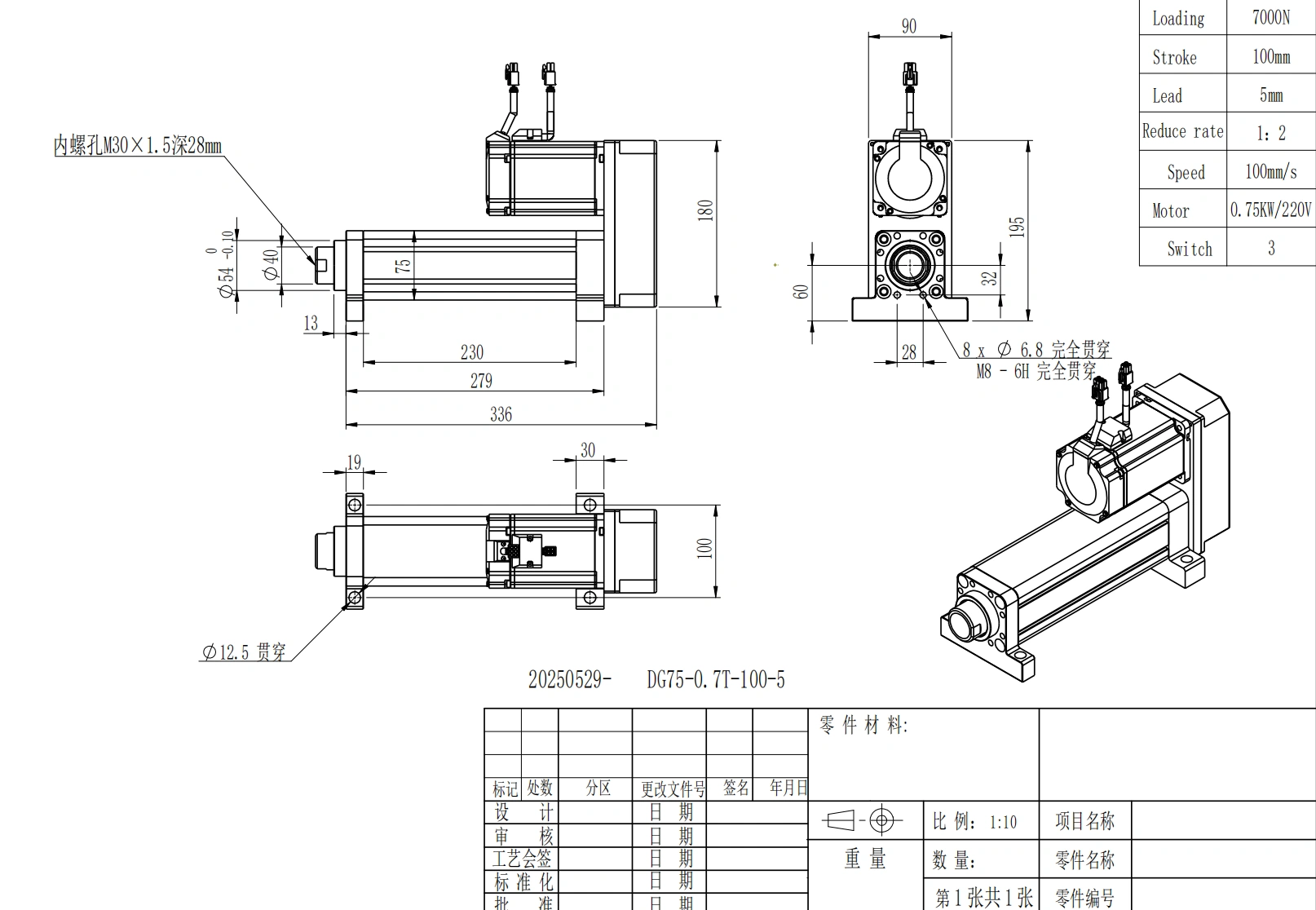
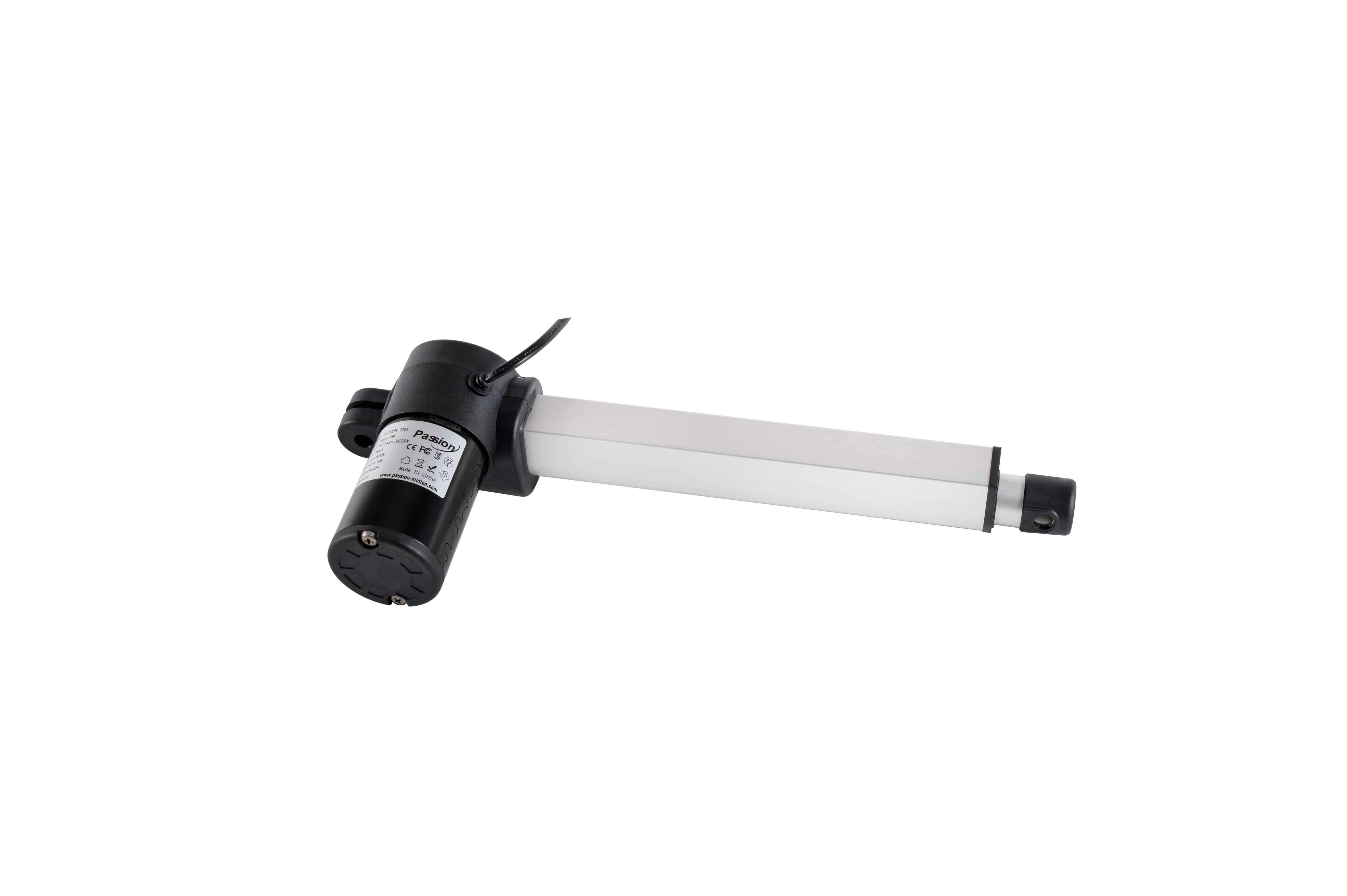
Cylinder-style construction is commonly paired with rotary-to-linear transmission; final suitability still depends on load, speed, stroke, duty, mounting, and control requirements.
Rod, Rodless, Slider, and Lifting-Column Formats Are a Different Dimension
Physical layout affects the machine envelope even when the underlying actuation technology is similar.
Rod-Style
A rod extends and retracts from the actuator body. This packaging is intuitive for push/pull motion and can fit linkages, pivots, lifting mechanisms, and other axial-load applications.
The engineering check is the load path. Side loads and moment loads are design-dependent, and the application may need external guidance or a guided actuator structure rather than asking the drive mechanism itself to carry off-axis loads.
Rodless, Slider, and Carriage Designs
In a rodless or slider architecture, the load moves on a carriage along the actuator body. The arrangement can reduce the extra space required by a fully extended rod and can integrate guidance for the payload.
That does not automatically make it better for every installation. Moment capacity, guide arrangement, contamination protection, cable routing, carriage length, and total installed geometry still need to be reviewed.
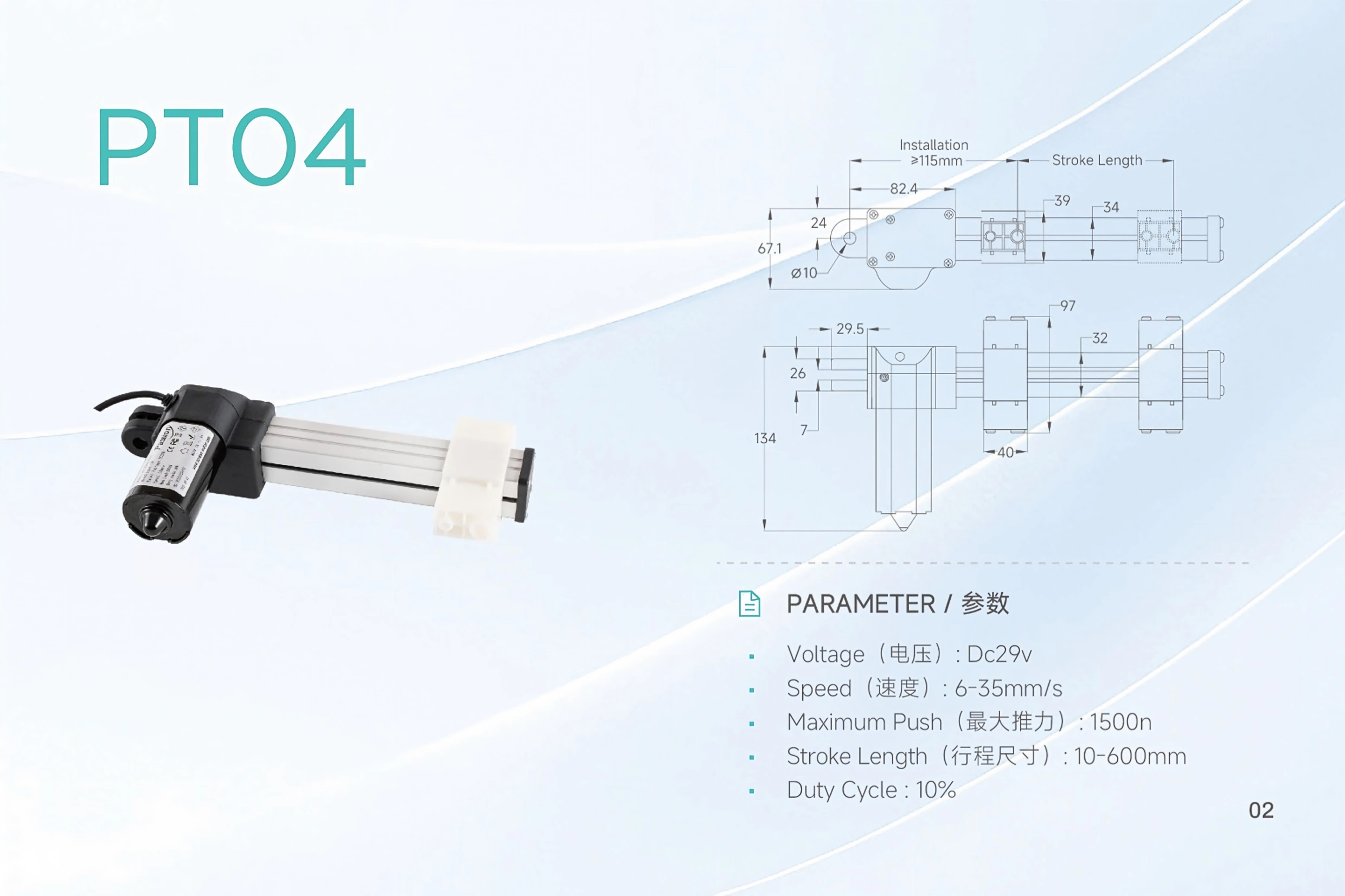
Compact and slider-oriented packaging affects installation geometry, but it does not replace the need to classify the drive mechanism and operating requirements.
Guided Axes and Lifting Columns
A guided axis combines actuation with a defined load-support structure. A lifting column is a more application-specific telescoping form that packages motion and guidance for vertical height adjustment.
These labels are useful when discussing integration, but they should not be confused with energy-source categories. A buyer still needs to know what drives the motion, how load is transferred, what guidance is included, and how the system is controlled.
How the Broader Electric-Actuator Query Fits This Taxonomy
The search phrase types of electric actuators is broader than the scope of a linear-motion article because electrically powered actuators can produce linear or rotary output. Rotary, quarter-turn, and multi-turn devices are common in other actuator markets.
For a machine that specifically needs straight-line motion, a better engineering sequence is:
electrical power source → motor or direct-actuation technology → linear-motion mechanism → physical architecture → feedback/control configuration.
That keeps the classification tied to the motion the machine actually needs.
How to Narrow the Type Before Detailed Sizing
A type comparison should eliminate unsuitable technology families. It should not replace force and geometry calculations.
Before moving to a product shortlist, define at least these requirements:
- Load and force direction: push, pull, lift, press, or position; include gravity and external forces.
- Stroke: required travel plus any installation or end-of-travel margin.
- Speed and motion profile: constant travel, acceleration/deceleration, cycle time, or multiple commanded positions.
- Duty cycle: how often and how long the actuator moves under load.
- Positioning requirement: simple end stops, repeatable intermediate positions, or closed-loop motion.
- Load guidance: whether the actuator carries only axial force or must also resist side and moment loads.
- Installation envelope: retracted length, extended geometry, mounting points, and clearance.
- Environment: dust, moisture, temperature, washdown, contamination sensitivity, and noise constraints.
- Available infrastructure: electrical power, compressed air, or hydraulic power.
- Maintenance strategy: lubrication, seals, hoses, belts, screw service, and access.
- Control integration: switches, sensors, controller, PLC, feedback, synchronization, and fault handling.
If the project is already at this stage, use the actuator sizing resource to organize force, stroke, speed, and safety-factor inputs before comparing exact models.
Common Classification Mistakes
Mistake 1: Mixing Power Source and Mechanism
“Pneumatic” describes where force comes from. “Ball screw” describes how rotary motion becomes linear travel. They should not be treated as equivalent labels in the same taxonomy level.
Mistake 2: Treating a Physical Shape as a Complete Technology Description
Rod, rodless, slider, and column formats tell you a great deal about installation geometry and load transfer, but not enough about the power source, internal transmission, feedback, or duty capability.
Mistake 3: Choosing From One Performance Attribute
A high force requirement can favor one family, while speed, precision, environment, or maintenance pushes the design toward another. Selection should be based on the requirement set, not one headline parameter.
Mistake 4: Assuming a Type Name Guarantees Performance
Two screw-driven axes can have different motors, screw leads, gear ratios, bearings, guidance, feedback, and thermal limits. The type narrows the architecture; the specification determines whether the exact product works.
Mistake 5: Comparing Components Instead of Systems
Pneumatic and hydraulic cylinders depend on external power and control infrastructure. Motor-driven axes depend on electrical supply, drive electronics, controls, and sometimes feedback or brakes. Compare the complete motion system needed by the machine.
Frequently Asked Questions
What are the main types of linear actuators?
At the highest level, common families include motor-driven electromechanical, pneumatic, hydraulic, mechanical/manual, and specialized direct-actuation technologies. Motor-driven systems can then be divided by screw, belt, rack-and-pinion, direct linear drive, and other mechanisms.
Why do different sources list different actuator types?
They often use different classification axes. One source may classify by energy source, another by drive mechanism, and another by physical shape. The lists are easier to reconcile when those layers are separated.
Is a screw-driven actuator a separate top-level family?
It is better treated as a mechanism within a broader motor-driven family. The screw describes how rotation is converted to linear travel; the motor and control system describe how the mechanism is powered and commanded.
Which type is best for high-force applications?
There is no universal answer. Hydraulic systems are often evaluated when high force density or shock tolerance is important, while motor-driven screw systems can also serve demanding thrust applications. Stroke, speed, duty, precision, environment, maintenance, and available infrastructure determine which option is practical.
Which type should I consider for long, fast travel?
Belt, rack-and-pinion, and some direct-drive architectures are often evaluated for long or fast axes. The final choice depends on payload, acceleration, positioning, rigidity, guidance, environment, duty cycle, and total travel.
Are rod and rodless actuators different energy-source types?
No. They describe physical architecture and how the load is carried or moved. A separate question is what power source and drive mechanism create the motion.
Do types of electric actuators include rotary motion?
Yes, in broad actuator terminology electrically powered devices can produce linear or rotary output. This guide is intentionally limited to linear-output motion so that the comparison stays relevant to straight-line machine movement.
What should I compare after choosing an actuator family?
Compare the exact force, stroke, speed, duty cycle, mounting, load guidance, environmental conditions, feedback, controls, power requirements, maintenance needs, and documentation for the candidate products.
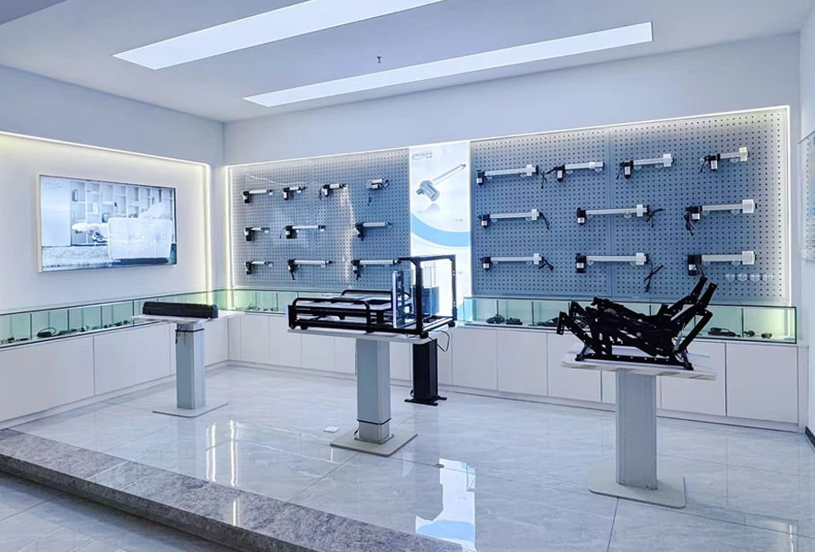
A useful actuator classification narrows the technology family; the final configuration still needs to be checked against the project requirement set.
Turn the Type Decision Into a Product Shortlist
A taxonomy is useful only if it reduces the design space. Once you have identified the plausible family and architecture, the next step is to compare actual products against the requirement set—not to keep collecting more type names.
You can review ServoCylMotion's linear actuator range for available product formats, then use the Product Selector to narrow the shortlist around the project requirements that matter.