Standing Desk Stroke and Height Calculation for OEM Frames
Calculate sit-stand frame travel from finished worksurface endpoints, then apply BIFMA G1-2013 and EN 527-1 dimensional inputs without confusing them with product certification.

For an OEM sit-stand frame, the first calculation is simple: define the required lower and upper finished worksurface positions , then subtract them.
ext T_{required}=H_{high}-H_{low}
That difference is the nominal finished travel. It is only the start of the engineering job. The frame still has to convert those surface endpoints into real mounting positions while accounting for tabletop thickness, rails and brackets, feet and leveling adjustment, lifting-column retracted length, usable motion, software limits, tolerance, load condition, and the exact standard or customer specification used for the program.
The practical rule is: size from the finished assembly inward, not from a catalog stroke outward.
Table of Contents
Start With Finished Worksurface Endpoints, Not Column Stroke
A lifting column may be advertised with a certain stroke, but the customer experiences the finished work surface. Those are different reference systems.
Define two controlled dimensions from the floor to the top surface:
- (H_{low}): required lowest finished worksurface position;
- (H_{high}): required highest finished worksurface position.
Then calculate nominal finished travel:
ext T_{required}=H_{high}-H_{low}
If the lower target is 650 mm and the upper target is 1250 mm:
ext T_{required}=1250-650=600 ext{ mm}
This does
not
mean the project can automatically specify a “600 mm column.” It means the complete product must provide at least a 600 mm finished-surface span under the defined configuration. The actual motion hardware has its own datums, compact dimensions, mechanical stops, control limits, and tolerances.
Before calculating anything else, put these references on the drawing:
- floor contact datum;
- lifting-column or frame mounting datum;
- top-frame/rail datum;
- underside of the tabletop;
- finished top surface;
- lower and upper released operating positions.
A controlled drawing removes the ambiguity hidden inside phrases such as “frame range,” “column length,” or “overall height.”
For a broader system-level view of load, controls, power, and architecture, the standing-desk motion solution is the commercial bridge; this article stays focused on the dimensional calculation.
Convert the Finished Surface Into Frame and Column Geometry
The finished work surface is the sum of the moving frame reference position and the fixed vertical stack above or below that reference.
A useful simplified relationship is:
ext H_{surface}=H_{frame_ref}+H_{fixed}
where (H_{fixed}) may include:
- tabletop thickness;
- mounting plate thickness;
- top rail or crossmember;
- rubber pad or isolator;
- bracket and adapter stack;
- foot or floor-interface offset, depending on the chosen datum.
Therefore:
ext H_{frame,low}=H_{low}-H_{fixed}
ext H_{frame,high}=H_{high}-H_{fixed}
If the same fixed stack applies at both endpoints, it cancels from the travel difference:
ext T_{frame} =(H_{high}-H_{fixed})-(H_{low}-H_{fixed}) =H_{high}-H_{low}
This is why a thicker reference top changes the
absolute frame endpoints
but, when the offset is constant, does not change the nominal endpoint difference.
That cancellation should not be overgeneralized. A variable geometry, a moving linkage, changing foot interface, elastic deflection, a position-dependent stop, or another non-constant term has to remain in the endpoint calculation.
For an OEM frame-only program, define a reference tabletop in the specification. Otherwise two teams can quote the same frame with different finished surface positions simply because one assumed a 20 mm top and another assumed 30 mm.
Finished surface targets must be translated into the actual mounting and installation dimensions of the selected motion hardware.
Use BIFMA G1-2013 as a Defined Design Input, Not a Certification Shortcut
BIFMA G1-2013 is an ergonomics guideline used to inform dimensional fit for computer workspaces. It should be treated as a design input for user accommodation , not as proof that a finished frame has passed a structural, durability, electrical, or safety test.
A commonly cited G1-2013 interpretation uses the following finished worksurface endpoints:
| G1-2013 design input | Finished worksurface position |
|---|---|
| Lower endpoint | 22.6 in (57.4 cm) |
| Upper endpoint | 48.7 in (123.7 cm) |
| Nominal span | 26.1 in (66.3 cm) |
The 26.1 in value is simply:
ext 48.7-22.6=26.1 ext{ in}
An UPLIFT G1-2013 height-range sheet presents the 22.6–48.7 in finished range with a
1 in tabletop
. That condition matters because the frame reference positions would be one inch lower than the finished surface if no other offset changed.
There is also a source conflict worth keeping visible in an engineering program. Some industry commentary cites an upper figure of 46.5 in rather than 48.7 in. Those are materially different requirements; a 22–46.5 in interpretation yields 24.5 in of span, not 26.1 in.
Do not average the values or treat them as interchangeable. The controlled requirement should identify the exact customer document, revision, dimensional interpretation, and reference top used for the project. BIFMA's height-adjustable-desk guidance should be checked together with the customer's specified edition and any applicable product-test requirements.
BIFMA Dimensional Guidance Versus Product Testing
The dimensional question is: Does the intended product cover the required user-fit envelope?
A product-test question is different: Does the defined desk configuration meet the applicable structural, stability, durability, or other test requirements?
The two evidence sets should be kept separate in the technical file. A dimensional calculation cannot be used as a substitute for a test report, and a test report does not automatically prove that every top thickness, frame option, accessory, or software configuration reaches the same surface range.
Apply EN 527-1:2011 at the Finished Work Surface
EN 527-1 covers dimensional requirements for office work tables. In the captured EN 527-1:2011 sample, a desk whose height can be changed by the user during use is classified as Type A .
For a Type A sit-stand work table, the captured EN 527-1:2011 sample table shows the following minimum finished worksurface range:
ext 650 ext{ mm to }1250 ext{ mm}
The nominal finished span is therefore:
ext 1250-650=600 ext{ mm}
The important word is
finished
. The 600 mm span is a furniture-level dimensional requirement derived from the lower and upper surface positions. It is not a universal actuator or lifting-column stroke formula.
The EN 527-1 sample also defines the measurement at the user-side front edge of the work surface and records the minimum and maximum adjustment positions. That is exactly why an OEM should use a controlled finished-surface datum rather than a loosely defined column endpoint.
The captured iTeh EN 527-1:2011 standards sample provides the dimensional basis used here. For a released product requirement, verify the current contracted edition and the relevant national adoption rather than relying on a web summary alone.
Keep EN 527-1 and EN 527-2 Separate
For this calculation:
- EN 527-1 supplies dimensional definitions and ranges.
- EN 527-2 addresses mechanical safety, strength, durability, and related performance requirements.
A frame can mathematically reach 650–1250 mm and still require separate evidence for stability, strength, durability, pinch/shear considerations, control behavior, electrical safety, or customer-specific validation.
This article therefore uses EN 527-1 as a dimensional input only. A product release should separately identify all applicable testing and documentation requirements.
Why Stroke and Retracted Length Must Be Checked Separately
After the finished span is known, the next question is whether the selected lifting architecture can deliver it and fit into the lower package.
Two dimensions must be controlled:
- usable travel/stroke : how far the motion system can move in the released configuration;
- retracted length : the compact installation dimension when the system is at its lower end.
They do not have one universal relationship.
Supplier data from Thomson and TiMOTION lifting-column references shows that different telescoping architectures use different relationships between stroke and compact length. Two-stage and three-stage arrangements, internal screw geometry, motor packaging, overlap, mounting faces, and control limits all change the result.
For OEM work, the safe method is not to infer one dimension from the other. Request the controlled supplier drawing and record both.
A useful release equation is:
ext L_{extended}=L_{retracted}+S_{usable}
but the datum definitions behind (L_{retracted}) and (L_{extended}) still have to match the actual installed drawing.
The minimum finished position can fail even when travel is long enough. For example, a long-travel column with a large compact package may not retract far enough into the available frame envelope. A more compact telescoping architecture may meet the lower endpoint even with the same nominal travel.
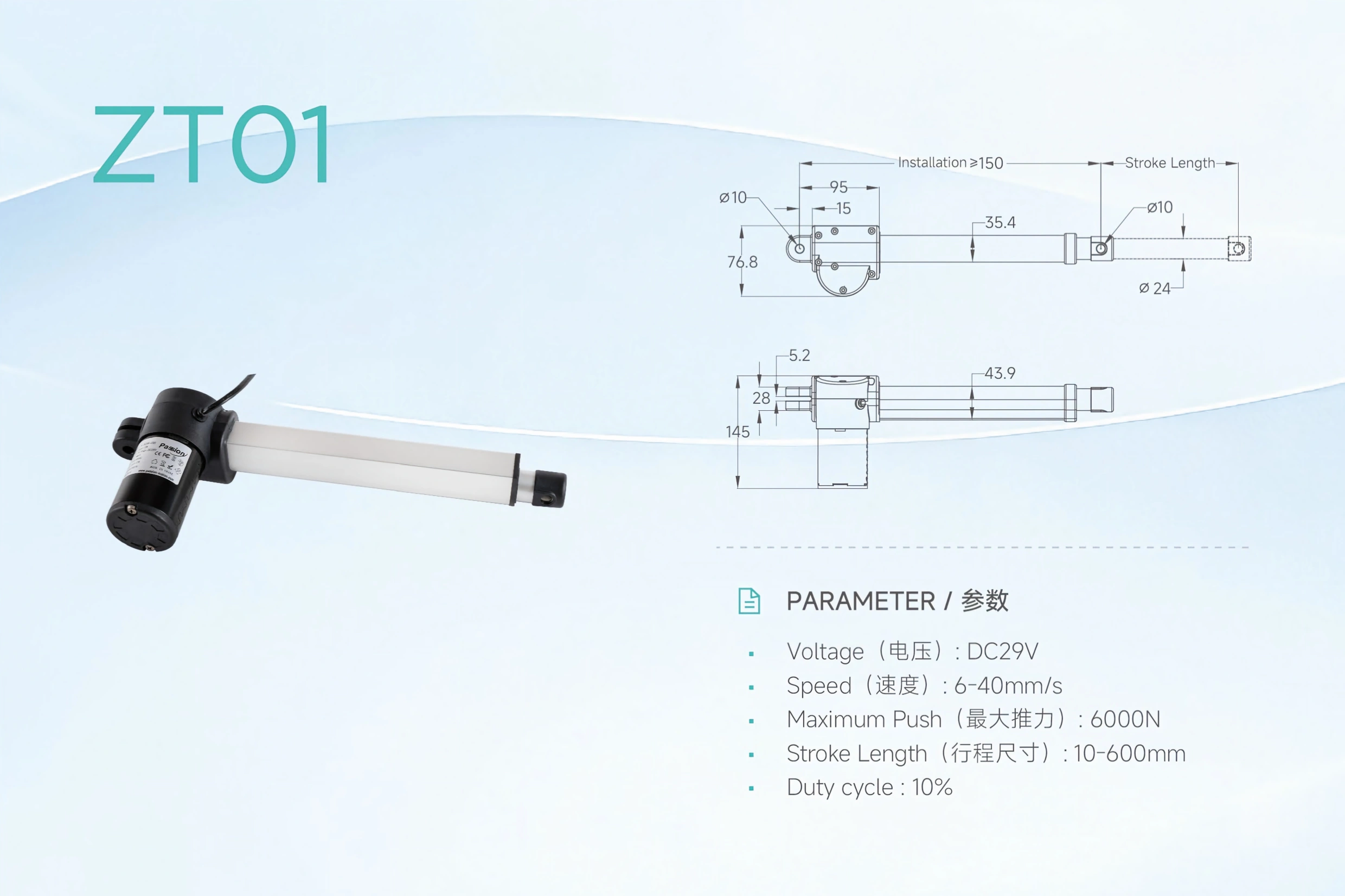
Travel and retracted dimensions are separate specification inputs and should be verified on the released drawing for the selected configuration.
Apply Tolerances and Release the Usable Range
Nominal arithmetic is not a production guarantee. Once a candidate architecture is selected, calculate the endpoint conditions that can actually be released.
Check at least:
- retracted-length tolerance;
- usable-stroke tolerance;
- tabletop thickness tolerance;
- rail, bracket, adapter, and fastener stack;
- leveling-foot adjustment range;
- column-to-frame mounting variation;
- synchronization behavior in multi-point systems;
- software upper/lower limits;
- homing or calibration offsets;
- structural deflection under the specified moving load;
- mechanical interference at both endpoints;
- cable service loop and strain relief through full travel.
Do not solve this with an invented universal percentage. The correct allowance depends on the actual tolerance chain and control strategy.
For a lower endpoint requirement, the critical case is often the assembly that ends up too tall when fully retracted. For an upper endpoint requirement, the critical case is often the assembly that ends up too low when fully extended.
A simple release structure is:
ext H_low,worst <= H_low,limit
ext H_high,worst >= H_high,limit
where each worst-case endpoint is calculated from the signs of the real dimensional contributors rather than by adding every tolerance in the same direction.
Control also matters. A mechanical column may have more physical travel than the controller exposes. Soft limits, synchronization logic, reset behavior, or safety functions can reduce the usable range. General motion sizing can be cross-checked with the actuator sizing resource , while the finished furniture calculation should remain tied to this article's surface datums.
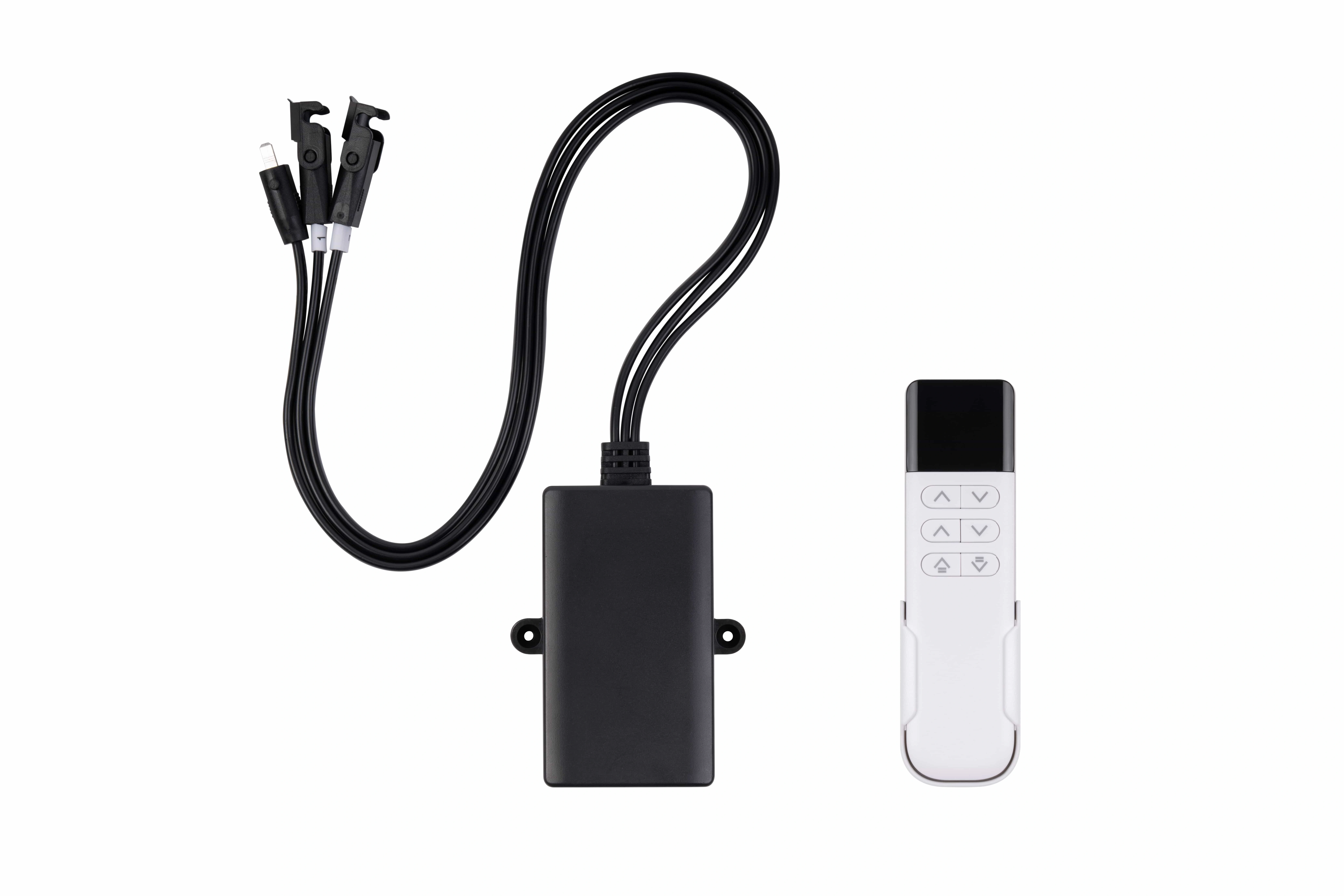
The released usable range depends on control limits and synchronization behavior as well as mechanical travel.
Worked OEM Example: From Surface Targets to Frame Endpoints
The following numbers are illustrative and are not ServoCylMotion product specifications.
Assume an OEM program defines:
- required lower finished worksurface position: 620 mm ;
- required upper finished worksurface position: 1220 mm ;
- reference tabletop thickness: 25 mm ;
- fixed rail/bracket stack below the tabletop: 35 mm .
First calculate the nominal finished span:
ext T_{required}=1220-620=600 ext{ mm}
The constant fixed stack is:
ext H_{fixed}=25+35=60 ext{ mm}
Convert the finished endpoints to the frame reference:
ext H_{frame,low}=620-60=560 ext{ mm}
ext H_{frame,high}=1220-60=1160 ext{ mm}
The frame-reference travel is still:
ext 1160-560=600 ext{ mm}
Now the real selection questions become clearer:
- Can the column/frame reach a released lower reference position of 560 mm?
- Can it reach at least 1160 mm at the upper end?
- Does the selected architecture provide at least 600 mm of usable synchronized travel?
- What is the retracted installation dimension at the controlled mounting datums?
- Do manufacturing tolerance, leveling adjustment, load deflection, and control limits preserve both endpoints?
- Is the offered configuration the same one represented by the supplier drawing and validation evidence?
This is more useful than writing “600 mm stroke required” at the top of an RFQ with no geometry.
OEM Standards and Travel Calculation Checklist
Before sending a requirement to a frame or motion-system supplier, define the following:
| Requirement | What to record |
|---|---|
| Market/customer document | Exact standard, guideline, customer specification, edition, and national adoption where relevant |
| Furniture class | Sit-stand use and applicable adjustment type/class |
| Finished lower endpoint | Floor-to-top-surface dimension and tolerance condition |
| Finished upper endpoint | Floor-to-top-surface dimension and tolerance condition |
| Reference tabletop | Thickness, material/configuration, and tolerance |
| Fixed stack-up | Rails, brackets, pads, adapters, foot interface, and other vertical offsets |
| Required usable travel | Difference between controlled lower and upper finished endpoints, plus project-specific release treatment |
| Retracted envelope | Maximum allowed compact installation dimension at controlled datums |
| Moving load | Complete moving assembly plus intended equipment and asymmetric cases |
| Control limits | Soft limits, reset/homing behavior, synchronization assumptions, and fault response |
| Tolerance method | Endpoint worst-case or other agreed production-capability method |
| Evidence | Controlled drawing, configuration record, test/report requirements, and revision control |
A complete dimensional requirement should be reproducible by another engineer from the controlled drawing and the input table alone.
OEM release should verify the finished assembly against controlled dimensions, configuration limits, and the required documentation.
For supporting engineering documentation and calculation tools, use the ServoCylMotion engineering resources .
FAQ
Does tabletop thickness change the nominal travel requirement?
If tabletop thickness and the rest of the vertical stack remain constant at both endpoints, they shift the absolute frame positions but cancel from the travel difference. Thickness still has to be controlled because it determines the finished lower and upper positions.
Is BIFMA G1-2013 a product certification requirement?
Treat G1-2013 as ergonomics/dimensional design guidance. Product testing, certification, and customer approval require their own applicable standards, configurations, and evidence. Do not use a dimensional range alone as proof of certification.
Why do published G1 references show different upper endpoints?
The sampled sources include both 48.7 in and 46.5 in interpretations. A controlled OEM requirement should name the exact document, edition, interpretation, and reference configuration instead of mixing the figures.
What EN 527-1 class applies to an electrically adjustable sit-stand work table?
In the captured EN 527-1:2011 sample, Type A is the classification for a work table whose height can be changed by the user during use. Confirm the edition and national adoption specified by the customer before product release.
Does the EN 527-1 Type A range mean I need a 600 mm lifting column?
Not automatically. The 650–1250 mm values define a 600 mm finished-surface span. The selected frame or column must be checked against its own datums, retracted package, usable travel, mounting geometry, tolerances, and control limits.
Is stroke the same as retracted length?
No. Stroke describes motion; retracted length describes the compact installation dimension. Their relationship depends on the selected column architecture and supplier design.
Should an OEM add a fixed percentage margin to the calculated span?
Not without a project-specific basis. Build the allowance from actual dimensional tolerances, leveling range, control limits, load/deflection conditions, and production verification rather than inventing a universal percentage.
What should be sent to a supplier for engineering review?
Send the exact market/customer standard, finished lower and upper positions, reference top, stack-up drawing, moving load, required usable travel, maximum retracted envelope, control assumptions, tolerance method, and required drawings/test evidence.
Turn the Calculation Into an OEM Requirement
The useful output from this calculation is not a single stroke number. It is a controlled set of finished endpoints, reference geometry, usable-travel requirements, compact-envelope limits, tolerances, controls, and evidence requirements.
If you are preparing a new sit-stand frame program, assemble those inputs first and then contact ServoCylMotion for an engineering review . That gives both sides a defined geometry to review before product selection or customization begins.
References
- BIFMA — Height-Adjustable Desks
- UPLIFT Desk — G1-2013 Height-Range Technical Sheet
- WorkWhileWalking — BIFMA G1 and Standing-Desk Standards Commentary
- iTeh Standards — EN 527-1:2011 Office Furniture Dimensions
- European Standards — DIN EN 527-1 Dimensions Overview
- CATAS — EN 527 Mechanical Safety and Performance Context
- Thomson — Lifting Columns
- TiMOTION — Lifting Columns