Servo-Driven Rod Axis Sizing & Selection Guide
Size a servo-driven rod axis by force, stroke, speed, duty cycle, screw lead, mounting, motor, drive, feedback, environment, and validation.

A servo-driven rod axis should be selected as a complete motion system, not from one headline force or speed number. The practical sequence is to define the machine requirement, calculate worst-case axial force, build the full motion and duty profile, set stroke and installed geometry, choose the screw and lead, check long-stroke mechanics, size the motor/drive/feedback package, and then validate the real cycle on the machine.
The key rule is: the final configuration has to satisfy all relevant limits at the same operating point. A maximum thrust value, maximum travel speed, maximum stroke, and maximum duty capability should never be assumed to be simultaneously available unless the configuration-level data says so.
Table of Contents
What you need before sizing
A useful sizing exercise starts with the application rather than the catalog. Record the worst-case operating values, including the process event that creates the highest force and the part of the cycle that creates the highest thermal demand.
| Input | What to define | Why it matters |
|---|---|---|
| Payload and moving mass | Workpiece, tooling, fixtures, moving machine components | Affects gravity and acceleration force |
| Process force | Pressing, clamping, forming, pushing, tensioning or other external force | Often dominates peak axial demand |
| Orientation | Horizontal, vertical or inclined | Changes the gravity component and holding strategy |
| Usable travel | Actual point-to-point travel plus required clearances | Sets stroke and installed geometry |
| Speed | Maximum and typical linear velocity | Drives screw rpm and motor speed |
| Acceleration/deceleration | Ramp time, move time and settling target | Adds inertial force and peak torque |
| Cycle | Extend, dwell, retract, dwell, cycles per hour | Determines continuous and thermal demand |
| Mounting and guidance | Flange, clevis, trunnion, rigid/pivoting mount, external guide | Affects alignment, buckling and side-load handling |
| Control requirement | Position, velocity, force/current, synchronized motion | Determines motor, drive and feedback needs |
| Environment | Temperature, dust, moisture, chemicals, washdown | Can change allowable components and derating |
| Life target | Required travel, cycles and maintenance interval | Influences screw technology and lubrication plan |
If this information is incomplete, use the sizing resource to organize the requirement before comparing hardware.
Start selection from the machine requirement, then verify the physical package against the available installation envelope.
Step 1: Calculate worst-case axial force
For a straightforward translating axis, the required axial force can be organized as:
F_axis = F_process + F_friction + F_gravity + F_acceleration + F_other
For a moving mass (m):
F_acceleration = m × a
For an axis inclined by an angle θ above horizontal:
F_gravity = m × g × sin(θ)
A vertical lifting axis therefore includes the full gravitational term (mg). A horizontal guided axis may have little gravity force in the travel direction, but it can still have guide friction, process force and acceleration demand.
This equation is a starting model, not a substitute for understanding the mechanism. Linkages, cams, pivots and changing lever arms can create a worst-case force at one point in the stroke. If the machine already exists, measured force or pressure data can be more useful than a rough nameplate estimate.
Separate holding, peak and continuous demand
Do not reduce the requirement to one force number.
Holding or static demand describes the force needed while the axis is not accelerating. Peak demand can occur during acceleration or a short process event. Continuous demand is governed by the complete motion cycle and thermal limits.
For servo sizing, a short high-force event can be acceptable while the average cycle remains much lower. The reverse can also happen: a modest load repeated almost continuously can become a thermal problem even when peak capability looks generous.
This is why force must be evaluated together with time.
Step 2: Build the full motion and duty profile
Write the cycle as actual segments:
move out → dwell → process event → move back → dwell
For each segment, define force, velocity, acceleration and duration. Then identify:
- the highest instantaneous axial force;
- the highest linear speed;
- the acceleration and deceleration needed to meet cycle time;
- the average or equivalent demand over the complete cycle;
- how long the axis remains at high force;
- how much dwell time is available for cooling.
A short move may be triangular, meaning the axis starts decelerating before reaching a constant-speed section. Longer moves may use a trapezoidal or S-curve profile. The exact trajectory matters because acceleration contributes to force and because the motor and drive must produce the required torque/current during each segment.
A common sizing mistake is to use travel distance divided by total cycle time as the design speed. That can substantially understate the required peak speed when the cycle contains acceleration, deceleration and dwell.
Peak capability is not continuous capability
Servo motors, drives and screw mechanisms commonly have separate short-duration and continuous operating regions. The complete cycle therefore has to pass two questions:
- Can the system deliver the short peak force and speed?
- Can it repeat the cycle without exceeding continuous current, torque, screw, bearing or thermal limits?
Neither check replaces the other.
Step 3: Set stroke, installed length and mounting
Required travel is not the same as required installation space.
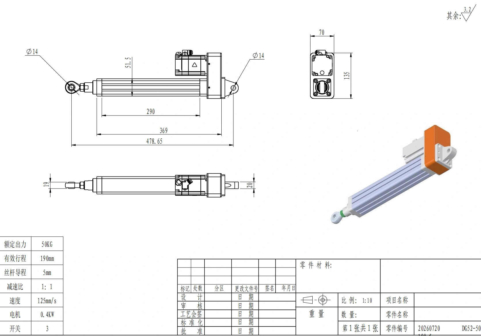
Start with the useful machine travel, then account for end clearances, homing behavior, tooling clearance and any service position. Next, check the complete physical package:
- retracted body length;
- required stroke;
- rod-end hardware;
- front flange, clevis, foot or trunnion mount;
- motor and brake;
- gearbox or parallel drive if used;
- connector and cable clearance;
- access needed for assembly and maintenance.
A parallel motor arrangement can shorten the axial package but introduces a different mechanical layout. A direct motor arrangement may be simpler but longer. CAD review should happen before the surrounding machine frame is frozen.
For available drawings, use the CAD and datasheets library rather than estimating package length from a product photograph.
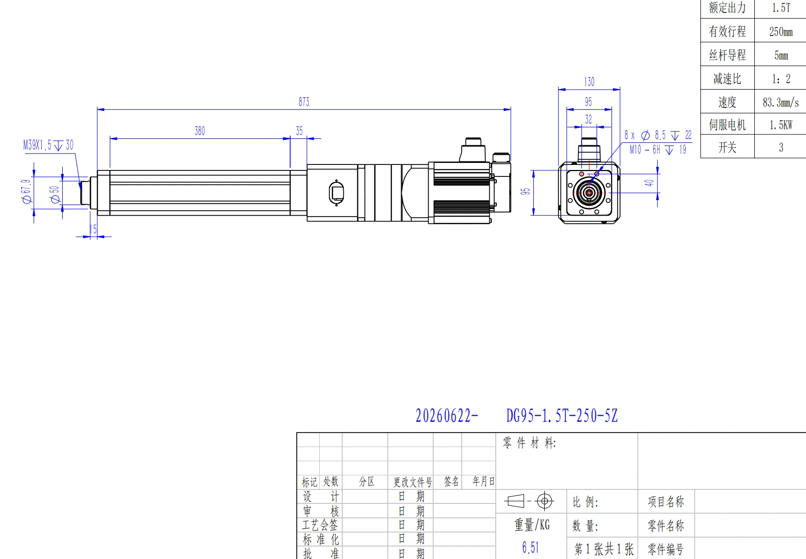
Required travel is only one part of the geometry check; body length, mounting hardware, motor package, and service clearance also matter.
Mounting affects mechanics, not only packaging
Longer strokes and compression loads increase sensitivity to support conditions. Pivoting mounts and rigid mounts create different effective end conditions, so the mounting method belongs in the mechanical sizing process.
Alignment also matters. A rod-style motion axis is fundamentally intended to transmit axial force. If the tool generates radial load, eccentric load or an overturning moment, provide appropriate external guidance or use a guided architecture that is designed to carry those loads.
Do not use the rod end to compensate for a misaligned machine structure.
Step 4: Choose screw technology and lead
Screw selection is a system trade-off among force, speed, efficiency, duty cycle, life, stiffness, backdrivability, cost and maintenance.
| Screw technology | Typical reason to consider it | Main checks |
|---|---|---|
| Lead/Acme type | Moderate speed/load, cost sensitivity, possible resistance to backdriving | Efficiency, heat, wear, backlash, real holding behavior |
| Ball screw | Higher efficiency, speed, positioning performance and long travel life | Backdrivability, lubrication, life, critical speed |
| Roller screw | High thrust, stiffness or demanding duty | Cost, friction, lubrication, configuration-specific life and speed limits |
The correct choice depends on the operating point. A screw technology that looks attractive at low speed may not be the best choice for a fast, high-cycle profile.
Screw lead connects linear speed to motor speed
For screw lead (P) and linear velocity (v), screw rotational speed can be expressed as:
n_screw = 60 × v / P
when v and P use consistent units.
A larger lead produces more linear travel per revolution, reducing screw rpm for a given linear speed. It also reduces mechanical advantage, so the motor may need more torque for the same axial force. A smaller lead increases mechanical advantage but requires more screw rpm to reach the same linear velocity.
The final lead therefore has to satisfy both the force requirement and the speed requirement with an acceptable motor operating point.
For a direct screw drive, a useful first-order torque relation is:
T_screw ≈ F × P / (2π × efficiency)
where F is axial force, P is screw lead, and efficiency is the mechanical efficiency of the screw transmission. This is only the load torque term; acceleration torque, rotating inertia, gearing and losses must also be included in the servo calculation.
Step 5: Check long-stroke mechanics and guidance
A motor can have enough torque while the mechanical transmission is already outside a safe operating region.
Two checks become especially important as stroke and unsupported length increase.
Buckling under compression
A long screw or thrust member can become unstable under compression. Buckling capability depends on unsupported length, root diameter, stiffness and end-support condition. The ideal Euler relationship shows why allowable compression decreases rapidly as unsupported length increases:
F_cr = π² × E × I / (K × L)²
Use this relationship to understand the physics, but use the selected configuration's approved buckling data for final design. Mounting conditions and real support geometry matter.
Critical screw speed
A rotating screw also has a critical-speed limit. Excessive rpm at a given unsupported length can cause whip, vibration, noise and accelerated wear. A long stroke may therefore become speed-limited mechanically even when motor torque is sufficient.
Final selection should pass, independently:
- axial force;
- screw speed;
- buckling;
- screw/bearing life;
- side-load or moment limits;
- thermal/duty constraints.
A generic safety margin cannot replace these separate engineering checks.
Step 6: Size the motor, drive and feedback as one system
Once the mechanical operating point is defined, the servo package can be sized.
Motor checks
The motor needs to satisfy:
- required screw rpm;
- peak torque during acceleration and process events;
- continuous/RMS torque over the complete cycle;
- reflected load and transmission inertia;
- brake requirement where applicable;
- ambient and thermal conditions.
Do not choose a motor from rated power alone. Two motors with similar power ratings can have very different torque-speed curves and peak capability.
Drive checks
The drive must be electrically and functionally compatible with the motor and application. Verify:
- continuous and peak current;
- supply/bus voltage;
- regenerative-energy handling;
- feedback protocol;
- communication interface;
- position, velocity and torque/current operating modes;
- required safety functions;
- brake control and timing where used.
Feedback checks
Motor feedback may be sufficient when the process can tolerate screw, coupling and structural errors. If the final workpiece position must be measured independently of the motor, consider load-side feedback such as a linear scale. If process force itself is critical, a calibrated force sensor may be more appropriate than estimating force only from motor current.
For systems that need compatibility review across motion components, see the product selector and technical documentation .
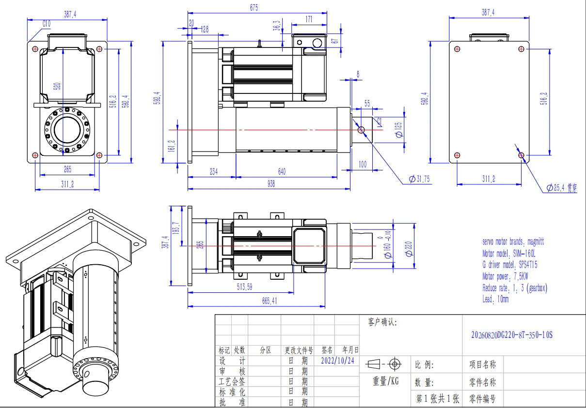
Mechanical transmission, motor, drive, feedback, and mounting limits should be verified as one configuration rather than as independent catalog maxima.
Step 7: Verify environment, vertical holding and commissioning
The operating environment can change a technically correct selection into an unsuitable one. Confirm temperature, contamination, moisture, cable flexing, chemical exposure, lubrication requirements and maintenance access for the complete assembly.
An enclosure rating should not be treated as automatic approval for every washdown fluid, corrosive chemical or immersion condition. Environmental suitability is configuration-specific.
Vertical axes need a defined power-loss strategy
A backdrivable transmission can allow a vertical load to move when motor torque disappears. The machine design therefore needs an intentional holding and safety strategy. Depending on the risk assessment, that can involve a spring-applied brake, counterbalance, mechanical restraint, safe drive functions or other measures.
A motor brake should not automatically be treated as the entire personnel-safety architecture. Define what the load must do during power loss, drive fault, emergency stop and maintenance.
Commission progressively
Do not commission a new axis for the first time at full speed and load. A practical sequence is:
- Inspect mounts, fasteners, guidance, rod-end freedom and cable routing.
- Move through the required travel at reduced speed and acceleration.
- Confirm feedback direction, scaling, homing and limits.
- Verify brake and safety behavior.
- Tune at low load before increasing the real process load.
- Run the actual production motion profile.
- Record current, temperature, following error, cycle time and process performance.
- Continue long enough to evaluate the real thermal duty, not only a few successful cycles.
If measured current, temperature or following error is much higher than predicted, investigate alignment, friction, load assumptions and motion profile before simply increasing control gains.
A practical selection worksheet
Use this handoff table before asking a supplier or application engineer to finalize a configuration.
| Requirement | Project value |
|---|---|
| Process description | |
| Moving mass | |
| Required process force | |
| Orientation | |
| Useful travel | |
| Target move time | |
| Maximum linear speed | |
| Acceleration/deceleration target | |
| Complete cycle including dwells | |
| Cycles per hour / operating hours | |
| Mounting method | |
| External guidance | |
| Available installation envelope | |
| Position/repeatability requirement | |
| Force-control requirement | |
| Feedback preference | |
| PLC / communication requirement | |
| Power-loss holding requirement | |
| Ambient/environmental conditions | |
| Required service life | |
| Quantity |
For standard industrial applications, the product-family overview can be the next comparison step. When thrust, stroke, mounting or integration requirements fall outside standard configurations, move directly to custom motion engineering .
Common sizing mistakes
The most expensive mistakes usually come from skipping a constraint, not from making a difficult calculation. Watch for these patterns:
- selecting from static weight while ignoring acceleration and process force;
- using only peak capability and ignoring continuous thermal demand;
- assuming maximum thrust and maximum speed are available together;
- choosing stroke without checking total installed length;
- ignoring long-stroke buckling or screw critical speed;
- allowing tooling side load to pass through the rod without guidance;
- choosing screw lead without checking motor rpm and torque;
- choosing motor/drive by wattage rather than torque, current and feedback compatibility;
- assuming a vertical load is safely held whenever the servo is disabled;
- commissioning at full speed before verifying alignment and limits;
- treating generic safety factors as a replacement for configuration-specific engineering limits.
FAQ
What is the minimum information needed for a first sizing pass?
At minimum, provide moving mass or process force, usable travel, target speed or move time, orientation, complete cycle timing, mounting method and basic control requirements. Environment and life target should be added before final release.
What is the difference between static holding force and moving force?
Static holding force describes a non-accelerating condition. Moving force can include process load, friction, gravity and
m × a
acceleration force. A system that holds a load safely may still be undersized for the required acceleration or cycle rate.
Why is peak thrust not enough?
Peak capability answers a short-duration question. Repetitive motion also has continuous motor, drive, screw, bearing and thermal limits. Both the peak event and the full duty cycle must pass.
How does screw lead affect selection?
Lead determines linear travel per screw revolution. Larger lead generally reduces required screw rpm for a target linear speed but reduces mechanical advantage. Smaller lead increases mechanical advantage but requires more rpm for the same linear speed.
Why does a long stroke require extra checks?
Longer unsupported lengths can reduce buckling capacity under compression and lower allowable screw rpm before critical-speed problems occur. Installed envelope and alignment also become more demanding.
Can a rod-style axis carry side load?
Treat axial loading as the default design condition. Use external guidance or a guided architecture for significant radial loads, eccentric loads or moments, and verify the exact permissible limits for the chosen configuration.
How should a vertical axis be held after power loss?
Define the required safe behavior through a machine risk assessment. Depending on the application, the design may need a brake, counterbalance, mechanical restraint, safe drive functions or a combination. Do not assume active servo torque will remain available after a fault or power loss.
What should be measured during final validation?
Measure or record the variables that prove the original sizing assumptions: real cycle time, current/torque demand, temperature, following error, position repeatability, process force where relevant, and behavior during stops or faults.
From sizing worksheet to engineering review
A good RFQ does not start with a part number. It starts with the motion requirement. Send the completed worksheet together with drawings of the load path, mounting geometry and available envelope. ServoCylMotion can then review whether an existing configuration is appropriate or whether the requirement should go through custom engineering.