Lifting Column OEM Specification: Buyer & Engineering Checklist
Build a lifting column OEM specification covering load cases, travel, geometry, speed, duty cycle, controls, interfaces, validation, drawings and supplier evidence.

A useful lifting column OEM specification does more than list force, travel, and speed. It defines the application load case, the exact geometry that must fit, the performance conditions the supplier must meet, the control and electrical architecture, and the evidence required before a configuration is released.
For OEM sourcing and R&D teams, the safest way to write the requirement is to separate every important item into three layers:
- Requirement — the value, range, behavior, or limit the finished system needs.
- Verification condition — the load, voltage, temperature, position, direction, controller, test setup, or fault state under which the requirement is checked.
- Released evidence — the drawing, interface document, test report, configuration code, or inspection record that proves exactly what was approved.
That structure makes supplier responses comparable and prevents a headline catalog value from being mistaken for an application-level guarantee.
Table of Contents
The Three-Layer Rule for an OEM Specification
A statement such as “high load,” “fast,” “quiet,” “synchronized,” or “IP rated” is not yet a controlled requirement. It becomes useful only when an engineer can answer: under what condition, measured how, and for which exact configuration?
Use this simple pattern throughout the RFQ:
| Specification field | Requirement | Verification condition | Released evidence |
|---|---|---|---|
| Load | Define dynamic, holding, peak, and off-axis cases | State direction, position, load distribution, temperature, and cycle | Approved load-case sheet and drawing datums |
| Travel | Define usable motion and endpoint limits | Verify under stated load and control limits | Dimensioned drawing and configuration |
| Speed | Define minimum acceptable loaded speed | State voltage, load, direction, controller, and temperature | Performance test tied to configuration |
| Synchronization | Define maximum allowed mismatch and fault behavior | Test actual multi-column assembly with unequal load | Controller/feedback interface plus test record |
| Noise | Define acoustic limit only if needed | State measurement distance, room, mounting, load, and speed | Reproducible test report |
| Environment | Define exposure and ingress requirement | Test selected seals, connectors, cables, and enclosure | Configuration-specific qualification record |
This is also a practical way to compare quotations. A supplier can mark each row complies , deviation , not offered , or requires application test instead of answering with an unqualified “yes.”
1. Define the Load Case Before the Load Rating
The first engineering mistake to avoid is treating payload as the whole load case. A vertical mechanism can see axial force, bending, torsion, side load, shock, and unequal distribution at the same time.
At minimum, define:
- total moving mass, not only the customer payload;
- push/pull direction and installation orientation;
- dynamic operating load and static/holding load;
- peak or abnormal load cases where relevant;
- center-of-gravity location and how it moves through the travel;
- eccentricity and bending moments about the relevant axes;
- lateral force or guided-side-load assumptions;
- acceleration, deceleration, shock, and emergency-stop cases;
- the number of columns and expected load sharing;
- worst-case unequal loading for multi-column structures.
Supplier literature commonly separates load and travel information, and technical families can also distinguish moving and holding capability. That is a reminder that independent ratings should not be assumed to apply simultaneously. A supplier should review the combined application load case against the intended mounting and structure.
A supplier review should start from the real load path and mounting conditions rather than a single headline force value.
For a two- or four-column frame, also specify how much imbalance the structure can create. A nominal system payload divided evenly by the number of columns is only a starting calculation. Real frames can shift load toward one side because of the top structure, accessory placement, friction, or the moving center of gravity.
2. Freeze Stroke and Installation Geometry Separately
Travel answers “how far must it move?” Installation geometry answers “will it fit at both endpoints?”
Keep these as separate requirements:
- usable stroke;
- commanded motion range;
- lower and upper usable positions;
- homing or reference travel;
- mechanical end-margin requirement;
- retracted overall height;
- extended overall height;
- installation dimension between controlled mounting datums;
- profile and plate envelope;
- cable exit and bend clearance;
- nearby bracket, frame, and service clearance;
- allowable dimensional tolerances.
Telescoping architecture changes the relationship between travel and compact height. That is why the OEM should not choose a mechanism from travel alone. Supplier category pages from Thomson, LINAK, TiMOTION, and RK Rose+Krieger all show that lifting-column families differ in architecture, configuration, and system integration details.
A released 2D drawing should identify the exact datums, hole pattern, threads, plate dimensions, cable exit, selected options, and tolerance scheme. The 3D CAD should match that released configuration rather than act as an uncontrolled reference model.
3. Specify Loaded Speed, Duty Cycle, and Life Conditions
A speed value becomes comparable only when its test condition is clear. For acceptance, define the minimum performance that matters in the real product.
Record:
- minimum loaded speed;
- travel direction;
- applied load and load distribution;
- input voltage range;
- controller and firmware/configuration;
- ambient temperature;
- number of columns operating;
- acceleration/deceleration expectations;
- acceptable stopping distance or settling behavior;
- tolerance around the measured speed.
A no-load figure can help with early comparison, but it should not replace a loaded acceptance condition.
Duty cycle needs the same discipline. If the requirement is written only as a percentage, two suppliers may interpret it differently. Define the complete cycle: on-time, off-time, stroke fraction, load, ambient temperature, cycles per day, expected lifetime cycles, and recovery behavior after thermal protection if applicable.
For life validation, specify whether endurance cycling represents full travel, a repeated partial range, realistic payload changes, or a harsher qualification profile. The acceptance criterion should state what is measured after cycling: travel, current, speed, noise, synchronization, play, or other critical characteristics.
4. Treat Multi-Column Synchronization as a System Requirement
Multiple columns create a system problem, not just a motor problem. The specification should define both normal mismatch and behavior when something goes wrong.
Include:
- number of independently driven columns;
- feedback type and interface;
- maximum allowed height mismatch during motion and at rest;
- allowable transient racking;
- expected behavior with unequal load;
- homing/reference procedure;
- behavior after a power interruption;
- response to a disconnected feedback signal;
- response to a stalled or obstructed column;
- stop/reverse policy;
- cable-length constraints;
- controller identity, firmware, parameters, and diagnostic ownership.
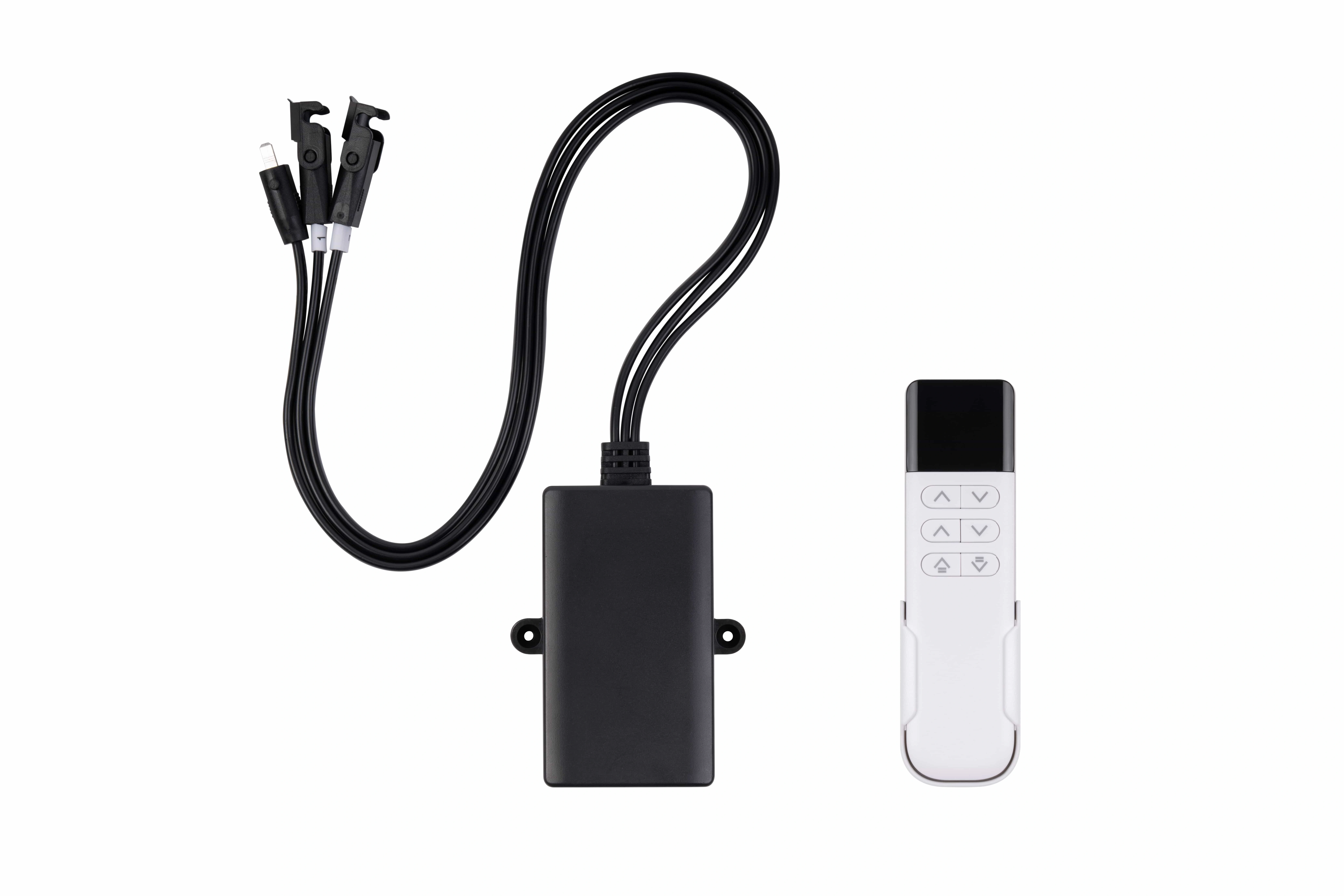
Multi-column behavior depends on the complete feedback and control architecture, so controller requirements belong in the system specification.
Supplier ecosystems often pair columns with specific controls and feedback arrangements. The OEM therefore needs a test using the intended platform, brackets, cable lengths, controller, and worst-case unequal load. A single-column bench result does not prove that a flexible frame will remain level in every operating condition.
For related system-level engineering, the project also maintains a dedicated multi-motor synchronization capability for applications that require coordinated motion behavior.
5. Lock Power, Controller, Cable, and Mechanical Interfaces
Electrical compatibility should be frozen early enough that the mechanical design does not outrun the control architecture.
The electrical portion of the specification should define:
- nominal and allowable input voltage;
- running, peak, inrush, and stall-current expectations where applicable;
- power-supply capacity and voltage-drop budget;
- polarity and grounding;
- connector family and pinout;
- cable length, gauge, bend radius, routing, and strain relief;
- feedback signal levels;
- limit-switch logic;
- emergency-stop interface;
- communication protocol and diagnostics;
- controller and firmware/configuration identity.
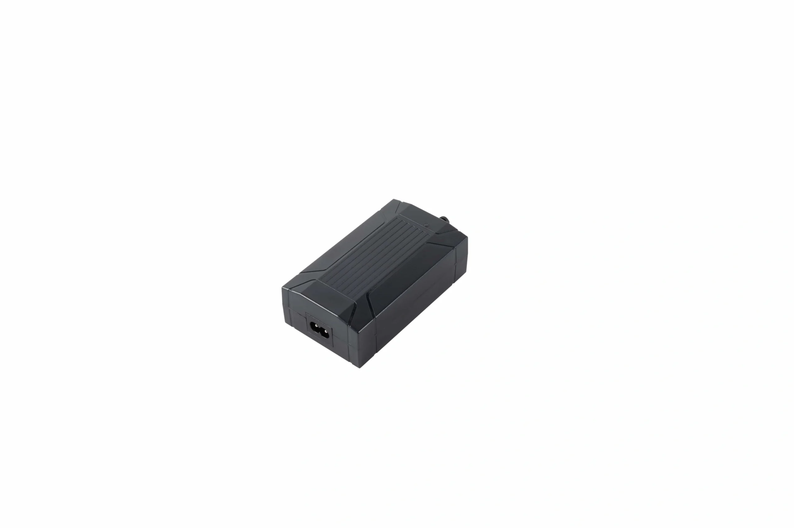
Power, connectors, cable length, and controller compatibility should be frozen as one electrical interface rather than selected independently.
The mechanical interface should be equally controlled:
- top and bottom mounting faces;
- hole pattern and datum scheme;
- fastener size and required engagement;
- maximum permitted screw depth where relevant;
- flatness and perpendicularity;
- alignment tolerance between multiple columns;
- bracket stiffness assumptions;
- allowable side-load or guidance assumptions;
- orientation and installation restrictions.
If the wider product needs a supplier-customized interface, the linear actuator OEM/ODM capability is a more appropriate commercial bridge than turning this engineering checklist into a catalog.
6. Make Noise, Environment, and Safety Requirements Testable
“Quiet” is not an acceptance criterion. If acoustic performance matters, define whether the limit is sound pressure, the weighting method, microphone distance, background-noise condition, mounting surface, room condition, load, travel direction, speed, controller, and number of columns.
Environmental requirements should start with the real exposure:
- dry indoor use or dust exposure;
- splash, washdown, or condensation;
- cleaning chemicals or disinfectants;
- humidity and temperature range;
- storage and transport conditions;
- corrosion or salt exposure;
- cable and connector sealing requirements.
An ingress classification should apply to the selected configuration, including cable exits and connectors, rather than being assumed from a broad family description.
Safety requirements also belong at system level. Define hazards, pinch/crush zones, guarding, end limits, overload behavior, obstruction response, brake/holding expectations, behavior on power loss, stop distance, restart behavior, and emergency-stop integration. A control feature marketed as anti-collision is not automatically a personnel-protection function; the finished equipment still needs application-specific risk assessment and validation.
7. Require a Configuration-Controlled Validation Package
The sourcing decision is not complete when the sample moves correctly. Before release, require documentation that ties the tested hardware to the approved production configuration.
A useful package can include:
- approved 2D manufacturing drawing;
- 3D CAD matched to the approved revision;
- interface-control drawing;
- electrical schematic and connector pinout;
- cable drawing;
- controller and firmware/configuration record;
- bill of material or configuration code;
- installation and service instructions;
- first-article inspection record;
- production acceptance procedure;
- loaded-performance report;
- endurance or duty-cycle qualification where required;
- environmental, acoustic, electrical, or safety reports appropriate to the project;
- deviation history;
- engineering-change notification process;
- traceability method.
Release evidence should identify the exact configuration, drawing revision, and acceptance criteria used for production and verification.
The key is configuration identity . A report is useful only when the buyer can tell which drawing revision, controller, cable, feedback option, and mechanical configuration were tested.
Technical files and controlled product documentation should be routed through the project’s engineering resources rather than copied informally between revisions.
OEM Lifting Column Specification Checklist
Use the following table as a pre-RFQ review. Leave a row open rather than inventing a value that has not yet been defined.
| Area | What the OEM should specify | Verification or evidence to request |
|---|---|---|
| Application | Orientation, moving mass, payload, CG, load cases | Load-case sheet and system drawing |
| Dynamic/holding load | Required operating and holding conditions | Test at stated position, direction, voltage, and temperature |
| Bending/torsion | Moments, lateral force, eccentricity | Combined-load engineering review or test |
| Travel | Usable stroke and endpoints | Dimensioned travel verification |
| Installation geometry | Retracted/extended envelope and mounting datums | Released 2D/3D drawing |
| Speed | Minimum loaded speed | Defined load, voltage, direction, controller, temperature |
| Duty/life | Cycle timing, load profile, ambient, lifetime target | Qualification procedure and acceptance criteria |
| Synchronization | Column count, feedback, maximum mismatch, fault behavior | Unequal-load system test |
| Controls | Controller, firmware, homing, diagnostics, stop/recovery behavior | Interface document and validation record |
| Power | Voltage range, current, supply margin, voltage drop | Electrical test and wiring data |
| Cable/connector | Pinout, gauge, length, routing, sealing | Released cable/interface drawing |
| Mounting | Hole pattern, fasteners, alignment, tolerances | Inspection drawing and assembly fit check |
| Noise | Reproducible acoustic limit if required | Defined measurement setup |
| Environment | Temperature, humidity, dust/water/chemical exposure | Configuration-specific qualification |
| Safety | Hazards, end limits, overload, obstruction, power-loss behavior | System risk review and functional validation |
| Quality | Critical dimensions and performance tolerances | First article and production acceptance records |
| Documents | Drawings, CAD, wiring, reports, revisions, change control | Configuration-controlled release package |
FAQ
What belongs in a lifting column OEM specification?
At minimum, define application load cases, usable travel, retracted/extended geometry, loaded speed, duty/life conditions, multi-column behavior, feedback and controls, power, connectors/cables, mounting interfaces, environment, safety behavior, tolerances, validation, and required documents.
Is a maximum load rating enough for selection?
No. The application may combine dynamic force, holding load, eccentricity, bending, lateral force, and unequal load sharing. The supplier should review the actual load envelope and mounting structure rather than only one headline capacity.
Why should stroke and retracted height be separate requirements?
Stroke defines displacement. Retracted height defines how compact the mechanism must be at the lower endpoint. Their relationship depends on the telescoping architecture and selected interfaces.
How should speed be specified?
Use a minimum acceptable speed under a defined load, voltage, travel direction, temperature, controller, and column count. That makes supplier responses much more comparable than an isolated nominal figure.
What should a duty-cycle requirement contain?
State the on/off time base, load, ambient temperature, stroke fraction, cycles per day or expected use profile, and any thermal recovery behavior. A percentage without those conditions is ambiguous.
What should be defined for synchronized columns?
Define the feedback method, controller, maximum mismatch, behavior under unequal load, homing process, power-loss recovery, and response to a stalled, obstructed, or disconnected column.
How should an acoustic requirement be written?
Specify the metric and measurement setup: distance, room/background condition, mounting surface, load, speed, direction, controller, and number of operating columns.
Which files should be required before production release?
Require the approved 2D/3D geometry, interface and wiring data, controller/configuration record, inspection criteria, relevant qualification/test reports, revision identity, and change-control process.
Turn the Checklist Into a Controlled RFQ
Before contacting a supplier, complete the load case, geometry, performance, control, interface, environment, and validation rows that your project actually needs. Where a value is still unknown, label it as an engineering decision rather than allowing a default to enter the design unnoticed.
For standing-desk programs, the standing-desk solution page is the commercial next step for system-level discussion. For a project-specific requirement review, contact ServoCylMotion with the completed checklist and the controlled drawings available at that stage.