Industrial Lifting Actuator Selection: Load, Holding, Duty, and Control Checklist
Use this industrial lifting actuator selection checklist to define payload, force margin, stroke, speed, duty cycle, holding, mounting, synchronization, power, environment, and validation.

Industrial lifting actuator selection should start from the complete vertical load case, not from payload alone.
A lifting axis has to move the payload plus the platform or fixture, overcome guide friction, accelerate and decelerate the moving mass, tolerate imbalance, fit within the machine envelope, hold or control the load when power is removed, and repeat the cycle without exceeding thermal or lifecycle limits.
For OEM engineers, the selection sequence is:
- define the complete moving mass and vertical load path;
- calculate the required force across the motion;
- define stroke and installed geometry;
- specify holding, backdrive, and power-off behavior;
- set speed and duty-cycle targets;
- keep side loads and moments in the guide structure;
- define single- or multi-point lift architecture;
- size power, controls, feedback, and cables;
- define environment and lifecycle;
- validate the production-intent assembly.
Table of Contents
Industrial lifting selection checklist
| Requirement | What to define | Why it matters |
|---|---|---|
| Payload | maximum lifted payload | only one part of the total moving load |
| Moving structure | platform, fixture, brackets, carriage, cables | adds directly to lifting force |
| Guide friction | worst-case guide/bearing resistance | raises required force and current |
| Acceleration | target acceleration/deceleration | adds dynamic force beyond gravity |
| Load imbalance | eccentric or unevenly distributed load | can increase friction and racking |
| Design margin | uncertainty, wear, friction, tolerances | prevents sizing at the edge |
| Stroke | required vertical travel | defines motion range |
| Retracted length | closed installation envelope | can limit packaging feasibility |
| Speed | loaded travel speed | affects cycle time and power |
| Duty cycle | run/rest profile | determines thermal suitability |
| Holding | required unpowered load behavior | moving force does not prove holding |
| Backdrive | allowed or prohibited load drift | critical for vertical axes |
| Side load | guide structure and alignment | protects screw/rod life |
| Axis count | one or multiple lift points | changes control architecture |
| Synchronization | allowable level mismatch | required for coordinated multi-point lifting |
| Power | continuous/peak current and voltage drop | mechanical fit is not enough |
| Feedback | position, limits, mismatch, diagnostics | enables controlled stopping and coordination |
| Environment | temperature, dust, liquid, corrosion | affects product and cable selection |
| Validation | load, holding, duty, faults, lifecycle | proves the real machine |
Industrial lift selection starts with the complete vertical load case, geometry, holding behavior, duty cycle, and control requirements.
This checklist is deliberately broader than force and stroke because most lifting failures are system-interface failures, not simply a lack of nominal thrust.
Step 1: Calculate the real vertical load
For a simple vertical axis, the actuator must overcome gravity plus the additional dynamic and friction forces in the machine.
The load case can include:
- payload;
- moving platform;
- fixtures;
- tooling;
- carriage;
- cable carrier;
- counterbalance effects;
- guide friction;
- seal/bearing friction;
- acceleration;
- shock or impact;
- load imbalance.
A basic engineering model is:
Required lifting force
= gravity load
+ guide/friction load
+ acceleration force
+ process/external load
+ design margin
The exact margin depends on uncertainty, application consequence, operating conditions, and validation evidence.
Use the actuator sizing tool after the load path is defined.
Payload is not the same as moving mass
A 500 kg payload on a 200 kg moving platform creates a different force requirement from a 500 kg payload on a lightweight carriage.
The requirements sheet should therefore separate:
- payload;
- moving machine mass;
- counterbalance force;
- guide friction;
- acceleration;
- external forces.
Step 2: Check the worst position, not one convenient position
Many lift mechanisms are not perfectly direct-drive.
If the axis pushes through:
- a lever;
- scissor linkage;
- pivot;
- offset bracket;
- inclined rod;
the force can change substantially through the stroke.
The most unfavorable geometry may occur near the start or end of travel.
For these mechanisms, calculate force at multiple positions and identify the peak operating requirement.
Step 3: Define stroke and installed length together
Required travel is only half of the geometry problem.
Also record:
- retracted length;
- extended length;
- mounting-center distance;
- motor/gearbox envelope;
- cable exit;
- connector clearance;
- bracket thickness;
- service-removal space.
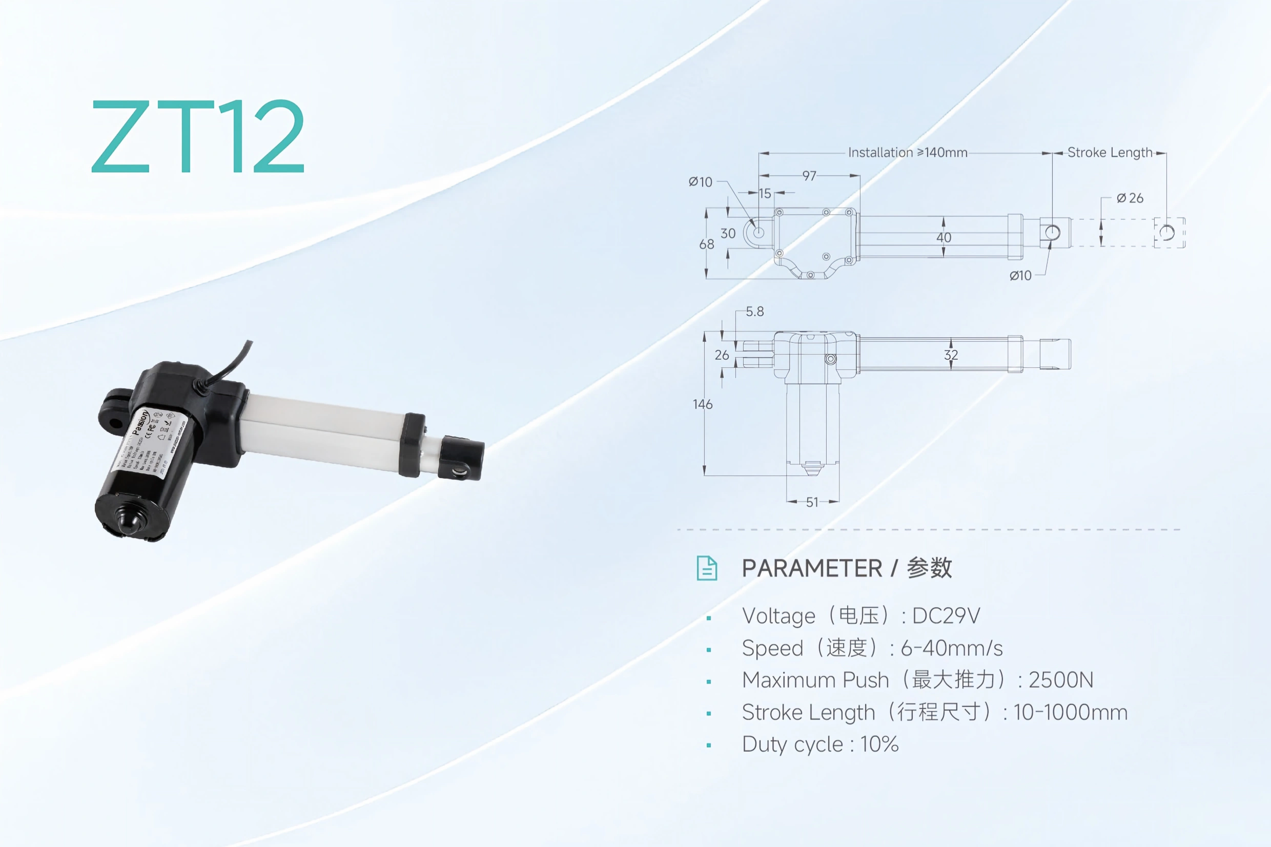
Similar travel can require different retracted length, mounting centers, guide structure, and cable clearance.
Two lifting components can provide the same stroke and still have very different packaging requirements.
A compact machine may therefore be limited by closed length before it is limited by force.
Verify the full CAD envelope
At both travel extremes, check:
- structural collision;
- cable pinch;
- connector interference;
- bracket angle;
- guide alignment;
- hard stops;
- tolerance stack.
The motion axis should remain primarily axially loaded throughout travel.
Step 4: Treat holding and backdrive as separate requirements
One of the most important vertical-motion questions is:
What happens when power is removed?
A component may lift the load successfully and still be unsuitable if gravity can drive it backward.
Possible requirements include:
- no load drift;
- mechanical self-locking;
- brake-held position;
- controlled lowering;
- counterbalanced descent;
- safe manual release.
PBC Linear and Thomson both highlight backdrive/load-drift considerations in screw-driven vertical motion.
Do not assume a screw type is self-locking in every load and lubrication condition.
Define the power-off state
The requirements sheet should state:
- whether the load must hold position;
- maximum allowed drift;
- whether a brake is required;
- brake-release logic;
- behavior after power loss;
- behavior after drive fault;
- manual-recovery method.
Moving-force rating is not proof of any of these behaviors.
Step 5: Define speed under load
Catalog no-load speed can be useful for comparison, but the machine needs a loaded speed requirement .
Specify:
- target travel time;
- acceleration;
- deceleration;
- loaded speed;
- stop distance;
- speed tolerance;
- low-line supply condition.
A faster axis may require:
- more motor power;
- higher current;
- different gearing;
- greater braking effort;
- more rigid structure.
Speed should therefore be selected together with force and duty cycle.
Step 6: Translate duty cycle into the real operating profile
Duty cycle is not just a percentage.
Record the actual cycle:
- lift time;
- hold time;
- lower time;
- idle time;
- cycles per hour;
- simultaneous axes;
- ambient temperature;
- enclosure ventilation.
A lift that moves once every ten minutes has a very different thermal requirement from a workstation that cycles continuously.
The motor, drive, screw, bearings, connectors, and power source all contribute to the thermal limit.
Step 7: Keep side load and moments in the guide structure
The lifting axis should provide axial force.
The machine guides should manage:
- platform moments;
- eccentric load;
- racking;
- side forces;
- rotational restraint.
Useful checks include:
- guide parallelism;
- bearing preload;
- frame stiffness;
- mounting-point tolerance;
- bracket deflection;
- pivot freedom;
- load center.
If the guide structure binds, motor current rises and service life can fall.
A higher force rating does not fix poor alignment.
Step 8: Decide whether one lift point is enough
A single axis can simplify the machine when:
- the platform is narrow;
- the load is centered;
- the guide system is torsionally stiff;
- the force path is well aligned.
Multiple lift points may be required when:
- the platform is wide;
- the load is distributed;
- structural stiffness requires multiple supports;
- one central drive is not practical.
Multiple axes require a synchronization specification
If two or more axes support the same structure, define:
- feedback type;
- channel count;
- allowable position mismatch;
- maximum following error;
- correction strategy;
- stop behavior if one axis stalls;
- reset/homing behavior;
- load-sharing assumption.
Multiple lift points require defined channel behavior, feedback, mismatch limits, and fault response.
Sending the same command to multiple motors is not proof that the platform will remain level.
For coordinated lifting, review multi-motor synchronization as a separate system requirement.
Step 9: Define power and controls as part of mechanical selection
A mechanically suitable axis is not valid if the electrical system cannot support it.
Freeze:
- supply voltage range;
- continuous current;
- startup/peak current;
- motor-drive interface;
- simultaneous-motion current;
- cable length;
- conductor size;
- connector rating;
- fusing/current limit;
- feedback interface;
- limit inputs;
- PLC or local controls;
- reset/homing behavior.
For known component candidates, use system compatibility to check the interfaces together.
Step 10: Define environment and ingress needs
Industrial lifting equipment may operate in:
- dust;
- moisture;
- washdown;
- outdoor exposure;
- corrosive atmospheres;
- high or low temperature;
- vibration;
- shock.
The requirement should state the actual environment.
Do not assume an enclosure rating alone proves long-term suitability for all environmental conditions.
Also consider:
- cable jacket material;
- connector sealing;
- corrosion protection;
- lubricant temperature range;
- condensation;
- maintenance access.
Step 11: Include inspection and lifecycle requirements
The OEM specification should define what is inspected over the machine life.
Examples:
- mounting fastener condition;
- guide wear;
- backlash;
- screw lubrication;
- brake function;
- cable damage;
- connector retention;
- noise increase;
- current increase;
- position drift.
A lifecycle plan should include:
- expected cycles;
- representative load;
- environmental condition;
- maintenance interval;
- post-test acceptance criteria.
Step 12: Validate the worst credible condition
Production validation should use the exact machine configuration.
Load
- maximum payload;
- maximum moving structure;
- eccentric load;
- friction at worst tolerance;
- low supply condition.
Motion
- full stroke;
- loaded speed;
- acceleration/deceleration;
- stop behavior;
- repeated cycles.
Holding
- unpowered hold;
- backdrive/drift test;
- brake test if used;
- power-loss response.
Alignment
- guide parallelism;
- bracket deflection;
- side-load check;
- full-travel binding check.
Multi-axis
- synchronization;
- one-axis fault;
- position mismatch;
- recovery/reset.
Electrical
- startup current;
- continuous current;
- peak/stall condition;
- voltage drop;
- connector temperature.
Environment and life
- duty/thermal test;
- temperature;
- contamination;
- cable flexing;
- lifecycle test.
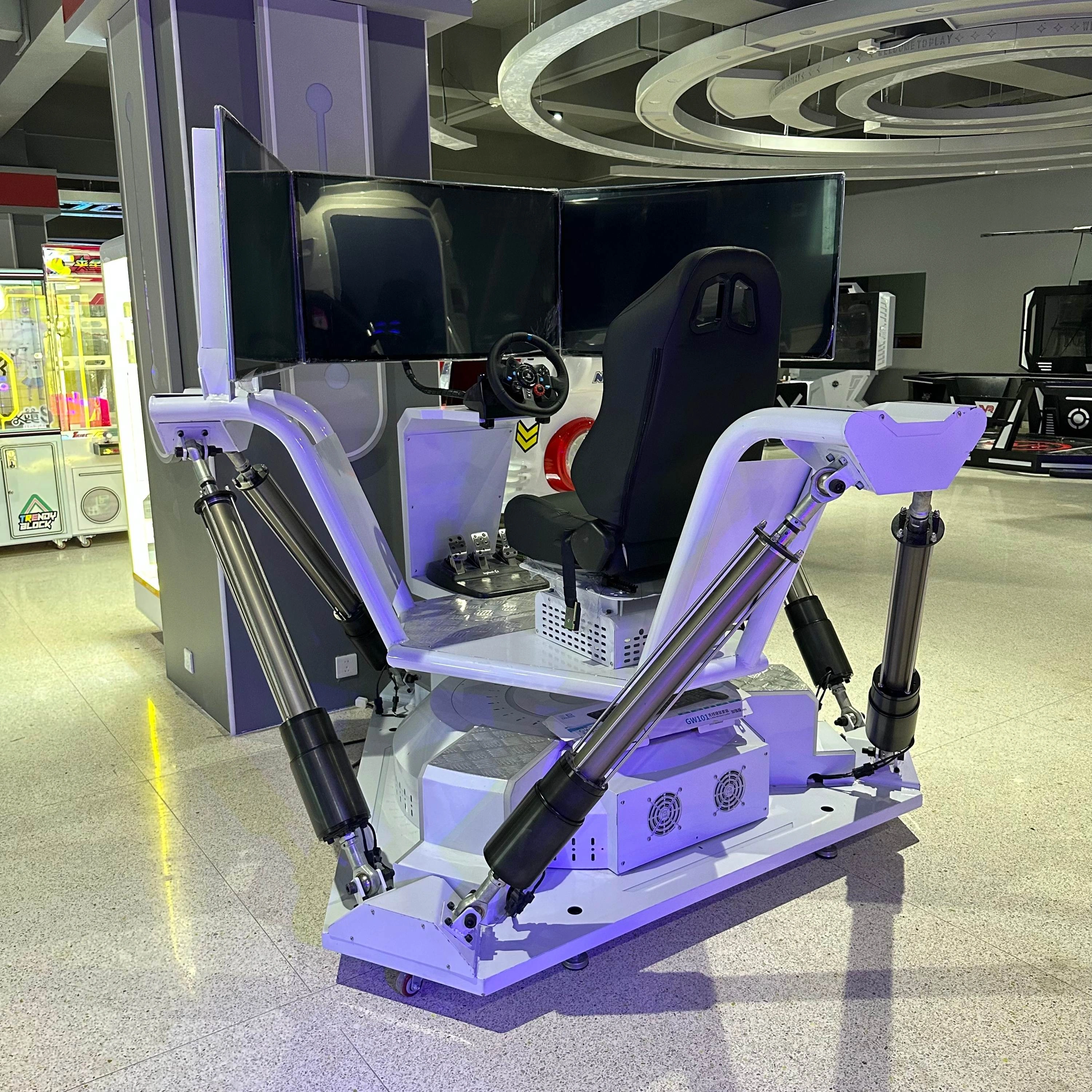
Production release should preserve the validated mechanical, electrical, parameter, and inspection state.
The exact mechanical, electrical, firmware, parameter, and inspection revision used in validation should be recorded.
OEM lifting requirements sheet
Before requesting a final product match, freeze:
Mechanical
- payload;
- moving mass;
- load direction;
- acceleration;
- guide friction;
- safety margin;
- stroke;
- retracted length;
- mounting geometry;
- side-load path.
Holding
- required power-off state;
- allowed drift;
- brake requirement;
- manual recovery.
Motion
- speed;
- cycle time;
- duty cycle;
- number of axes;
- synchronization tolerance.
Electrical
- voltage;
- current budget;
- feedback;
- controls;
- cable length;
- connector requirements.
Environment
- temperature;
- dust/liquid;
- corrosion;
- vibration/shock;
- service access.
Validation
- worst-case load;
- thermal cycle;
- holding test;
- fault test;
- lifecycle target.
After these inputs are defined, the product selector can narrow the candidate space.
For a commercial industrial solution context, use the industrial automation page . For project-specific review, send the completed requirements sheet through ServoCylMotion contact .
FAQs
What load should be used for industrial lifting selection?
Use the total moving load: payload, moving platform/fixture, guide friction, acceleration, imbalance, and any external force—not payload alone.
Why is backdrive a separate requirement?
Because a device can generate enough force to lift a load yet still allow gravity-driven movement when power is removed. Holding behavior must be verified separately.
Why does retracted length matter?
Because the axis must physically fit inside the machine in its closed position. Stroke alone does not define the installation envelope.
When are multiple lift points needed?
They may be needed for wide platforms, distributed loads, or structures that cannot be driven effectively from one point. If multiple axes are used, synchronization and fault behavior must be specified.
How should duty cycle be defined?
Use the real run/rest profile under representative load and ambient temperature, including simultaneous axis operation where applicable.
What should be validated before production?
Worst-case load, full stroke, loaded speed, holding/backdrive, duty/thermal behavior, alignment, multi-axis synchronization, power, faults, environment, and lifecycle should all be validated in the production-intent machine.