Linear Actuator Sizing Guide: Force, Speed & Stroke
Follow this linear actuator sizing guide to calculate force, apply a design margin, define speed and stroke, and prepare a clear actuator selection brief.

A reliable linear actuator sizing guide starts with the mechanism, not the actuator catalog. Define the load path and geometry, calculate the worst credible actuator-axis force, determine the required stroke, set the loaded speed, check duty cycle and mounting constraints, then compare the complete operating point with a real actuator configuration.
The most important sizing distinction is that payload weight is not automatically the same as required actuator force . Gravity, friction, acceleration, mounting angle, leverage, external process loads, and unequal load sharing can all change the force the actuator must actually produce.
For most B2B design work, use this sequence:
- Define the moving mass, motion direction, geometry, travel, cycle time, and environment.
- Draw a free-body diagram for each important load case.
- Calculate direct force or hinge torque at the worst credible operating condition.
- Apply an explicit design margin based on uncertainty and risk.
- Convert required motion into actuator stroke and installed endpoint lengths.
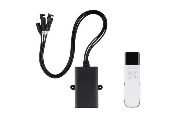
- Check loaded speed, duty cycle, mounting, guidance, and electrical limits.
- Validate the result against the selected configuration's current specifications and performance data.
This article explains the method. Once your inputs are defined, the ServoCylMotion actuator sizing worksheet can help organize the values for the next stage of selection.
Table of Contents
1. Define the Inputs Before You Calculate Force
Before doing a linear actuator force calculation , collect the data that describes the mechanism rather than starting from a desired actuator model.
| Input | What to define | Why it matters |
|---|---|---|
| Moving load | Payload, fixtures, moving structure, tools, cables, springs, process forces | Determines gravitational, inertial, and external resistance |
| Motion direction | Vertical, horizontal, inclined, or pivoting | Changes which force components act along the motion path |
| Geometry | Mounting points, center of gravity, hinge/pivot locations, actuator angle | Determines leverage and the useful component of actuator force |
| Travel | Start position, end position, clearances, required overtravel if any | Defines stroke and installed-length requirements |
| Speed | Required loaded travel speed or move time | Must be checked at the actual force, not independently |
| Acceleration | Acceleration/deceleration time or motion profile | Adds inertial force and can create the peak load case |
| Cycle profile | Extend time, retract time, dwell, cycles per hour | Determines thermal duty |
| Environment | Temperature, dust, water, corrosion, washdown, contamination | Affects enclosure, material, lubrication, and thermal requirements |
| Holding condition | Whether the load must remain stationary under force or after power loss | Requires a separate holding and safety review |
| System constraints | Voltage, current, controls, feedback, synchronization | Can limit usable actuator performance |
Use one unit system consistently. In the equations below, mass is in kilograms, force in newtons, distance in meters, torque in newton-meters, and gravitational acceleration is approximately:
g = 9.81 m/s²
2. Start With a Free-Body Diagram
The most reusable answer to how to size a linear actuator is to begin with Newton's second law along the intended direction of motion:
ΣF = m a
The actuator must overcome the forces opposing the desired motion and provide any force needed for acceleration. Depending on the mechanism, that can include:
- the component of gravity acting along the motion path;
- guide, bearing, seal, or sliding resistance;
- acceleration or deceleration force;
- spring force;
- cable or hose drag;
- process resistance;
- wind or other external loading;
- geometric losses caused by an angled line of action.
Do not combine all of these into one unexplained “safety factor.” Calculate known loads first. Use the design margin later for uncertainty and variation.
Vertical Lift
For a guided load moving upward, a useful first model is:
F_required = m g + F_resistance + m a + F_external
where:
-
m= moving mass; -
g= gravitational acceleration; -
F_resistance= measured or estimated guide/mechanism resistance; -
a= upward acceleration; -
F_external= additional process, spring, cable, seal, or other opposing force.
At constant speed,
a = 0
. During acceleration, the inertial term may make the start of the move the peak force condition.
Downward motion needs its own load case. Gravity may assist the movement, which can create a braking or load-retention requirement rather than simply a smaller motor-force requirement.
Horizontal Slide
For a horizontally guided load, gravity does not normally act directly along the travel direction. The force is more often dominated by guide resistance, friction, acceleration, and external loads:
F_required = F_resistance + m a + F_external
If the load literally slides on a surface and a friction coefficient is justified, resistance can be estimated from:
F_friction = μ N
For a horizontal surface,
N ≈ m g
, so:
F_friction ≈ μ m g
For linear bearings, rollers, or guided systems, use the resistance data for the actual mechanism when available instead of assuming a generic sliding-friction coefficient. Starting resistance should also be checked separately when breakaway force is higher than running resistance.
Inclined Motion
For a load moving upward on an incline, with the actuator force parallel to the direction of travel:
F_required = m g sin(θ) + F_resistance + m a + F_external
If sliding friction is modeled as
μN
and the actuator does not change the normal force:
N = m g cos(θ)

F_required = m g sin(θ) + μ m g cos(θ) + m a + F_external
Here
θ
is the incline angle measured above horizontal.
If the actuator is mounted at another angle, redraw the free-body diagram and resolve the actuator force into components. Avoid blindly dividing by a cosine when the actuator's perpendicular component also changes the normal force and therefore the friction term.
3. Hinged Loads Need Moment Balance, Not a Weight-Only Formula
A lid, hatch, flap, access panel, or pivoting arm is different from a guided straight-line load. The actuator produces a moment around the hinge, and its leverage changes as the mechanism moves.
For a simple static load:
τ_load = W × d_perpendicular
where:
-
W = m g; -
d_perpendicularis the perpendicular distance from the hinge to the load's line of action.
The actuator produces:
τ_actuator = F_actuator × r_actuator × sin(φ)
where:
-
r_actuatoris the hinge-to-moving-mount distance; -
φis the angle between the actuator line of action and the hinge-to-mount arm.
For static equilibrium:
F_actuator =
τ_total / [r_actuator × sin(φ)]
Add any spring, seal, latch, wind, process, or inertial torque to
τ_total
with a consistent sign convention.
The critical detail is that
φ
changes during the movement. When the actuator approaches a poor leverage angle,
sin(φ)
becomes small and required force rises sharply. Calculate several positions or evaluate the full mechanism in CAD rather than checking only the open and closed endpoints.
Stroke for a Hinged Mechanism
Stroke is the change in distance between the two actuator mounting pins, not the angular travel of the lid itself.
If the fixed and moving mounting points are located at radii
L1
and
L2
from the hinge, and their included angle is
γ
, the pin-to-pin actuator length can be calculated with the law of cosines:
L(γ) = √(L1² + L2² - 2 L1 L2 cos(γ))
Then:
Stroke_required = |L_end - L_start|
Check both calculated endpoint lengths against the candidate actuator's actual retracted and extended dimensions.
4. Worked Example: A Guided Vertical Load
The following example is illustrative only . It demonstrates the calculation sequence; it does not specify a ServoCylMotion model or establish a universal design margin.
Assume a guided vertical mechanism with:
-
moving mass:
100 kg; -
upward acceleration:
0.30 m/s²; -
measured/estimated mechanism resistance:
80 N; - no additional process force;
- one actuator carrying the complete axial load;
-
example design margin:
1.5.
Step 1: Calculate gravity force
F_gravity = m g
          = 100 × 9.81
          = 981 N
Step 2: Calculate acceleration force
F_acceleration = m a
               = 100 × 0.30
               = 30 N
Step 3: Add known resistance
F_peak_calculated
= 981 + 30 + 80
= 1,091 N
At constant speed, the acceleration term disappears, so the estimated running force would be lower. In this simplified case, the acceleration segment is the higher calculated condition.
Step 4: Apply the example design margin
F_preliminary
= 1,091 × 1.5
= 1,636.5 N
≈ 1.64 kN
The result is a preliminary specified-force target , not a product approval. Before choosing a configuration, you still need to verify loaded speed, push/pull direction, stroke, retracted and extended length, duty cycle, ambient conditions, mounting, electrical capacity, and the manufacturer's rating basis.
If the real mechanism has shock, uncertain friction, variable payload, human loading, severe temperature, or safety-critical consequences, the design margin and safety architecture need a separate engineering decision.
5. Choose a Design Margin Deliberately
A design margin accounts for uncertainty that remains after known forces are calculated. Typical reasons include:
- payload variation;
- friction growth with wear or contamination;
- manufacturing tolerances;
- alignment variation;
- temperature effects;
- shock or impact;
- unexpected process resistance;
- load imbalance between multiple actuators.
There is no single factor that is correct for every mechanism.
For a low-risk, well-characterized machine, uncertainty may be small. For a vertical load over people, shock-loaded machinery, outdoor equipment, or a mechanism with poorly known friction, the consequence and uncertainty are very different. Company design rules, applicable standards, risk assessment, and the selected actuator's rating method should control the final decision.
Also separate design margin from a safety function . A larger actuator alone does not replace a brake, mechanical restraint, safety nut, independent load support, guarding, or another required protective measure.
Multiple Actuators: Do Not Assume Perfect Load Sharing
A simple first estimate for
n
actuators is:
F_per_actuator = F_total / n
but that assumes the load is actually distributed evenly.
In real structures, center-of-gravity offset, frame deflection, mounting tolerances, control timing, and synchronization error can make one actuator carry more than its nominal share. Multi-actuator systems should therefore be checked for structural stiffness, synchronization strategy, position feedback where required, and the worst credible load imbalance.
6. Size Stroke and Verify the Installed Envelope
Required stroke is only one geometry check.
For direct linear motion:
Stroke_required ≥ required load travel
For linkages and pivoting mechanisms, derive stroke from the actuator's pin-to-pin distance at each endpoint.
Then verify all of the following:
- minimum retracted pin-to-pin length;
- maximum extended pin-to-pin length;
- bracket and clevis dimensions;
- clearance around the body, motor, cable, and moving rod;
- tolerance stack-up;
- mechanical end stops;
- whether the mechanism can reach an over-center or dead-center condition;
- thermal expansion where it matters;
- full-path interference in CAD.
Stroke must cover the required travel while the actuator still fits the mechanism at both endpoints.
A long stroke can also change other engineering limits. Screw-driven systems may need critical-speed checks at high screw speed and buckling checks when a long extended member is loaded in compression. These are configuration-specific calculations, so verify them from the selected actuator's engineering data rather than relying on a generic stroke rule.
7. Check Loaded Speed and Travel Time
If the load must move a known distance in a known time:
v_required = Stroke / Move_time
For example, moving
300 mm
in
10 s
requires an average travel speed of:
v_required = 300 / 10 = 30 mm/s
The important specification is the speed at the required load. Motor-driven actuators commonly trade force against speed through gearing, motor characteristics, and screw geometry. A configuration that can produce a high force may not deliver the same speed as a lower-force version.
For that reason, do not approve a design by checking the maximum force and maximum speed as two unrelated headline numbers. Verify that the required force-speed operating point exists for the same configuration, voltage, direction, and operating conditions.
Also account for acceleration and deceleration if move time is tight. A mechanism that needs
30 mm/s
average speed may require a higher peak speed after ramp time is included.
8. Duty Cycle Is a Thermal Sizing Input
Duty cycle expresses how much of a reference period the actuator is actually running.
For a repeated cycle:
Duty cycle (%) =
Motor-on time / Total reference time × 100
If an actuator runs for
8 s
extending and
8 s
retracting, 30 times per hour:
Run time per hour
= (8 + 8) × 30
= 480 s

Duty cycle
= 480 / 3,600 × 100
≈ 13.3%
That arithmetic is only the beginning. The allowed duty depends on the real configuration, load, stroke, ambient temperature, direction, cooling conditions, and manufacturer rating method.
High load, high ambient temperature, frequent reversals, and long run times can reduce thermal margin. A force-and-stroke match that overheats in the actual cycle is not correctly sized.
9. Check Mounting, Alignment, and Side Loads
A linear actuator should not automatically be treated as the machine's guide structure.
Where the selected actuator is intended primarily for axial push/pull loading, use appropriate guide rails, bearings, rollers, columns, or structural members to carry:
- transverse loads;
- overturning moments;
- racking;
- payload eccentricity;
- misalignment forces.
Pivoting mechanisms should allow the actuator to follow the changing line of action without forcing the rod or housing into bending. Brackets and pins must also be strong and stiff enough to transfer the calculated load.
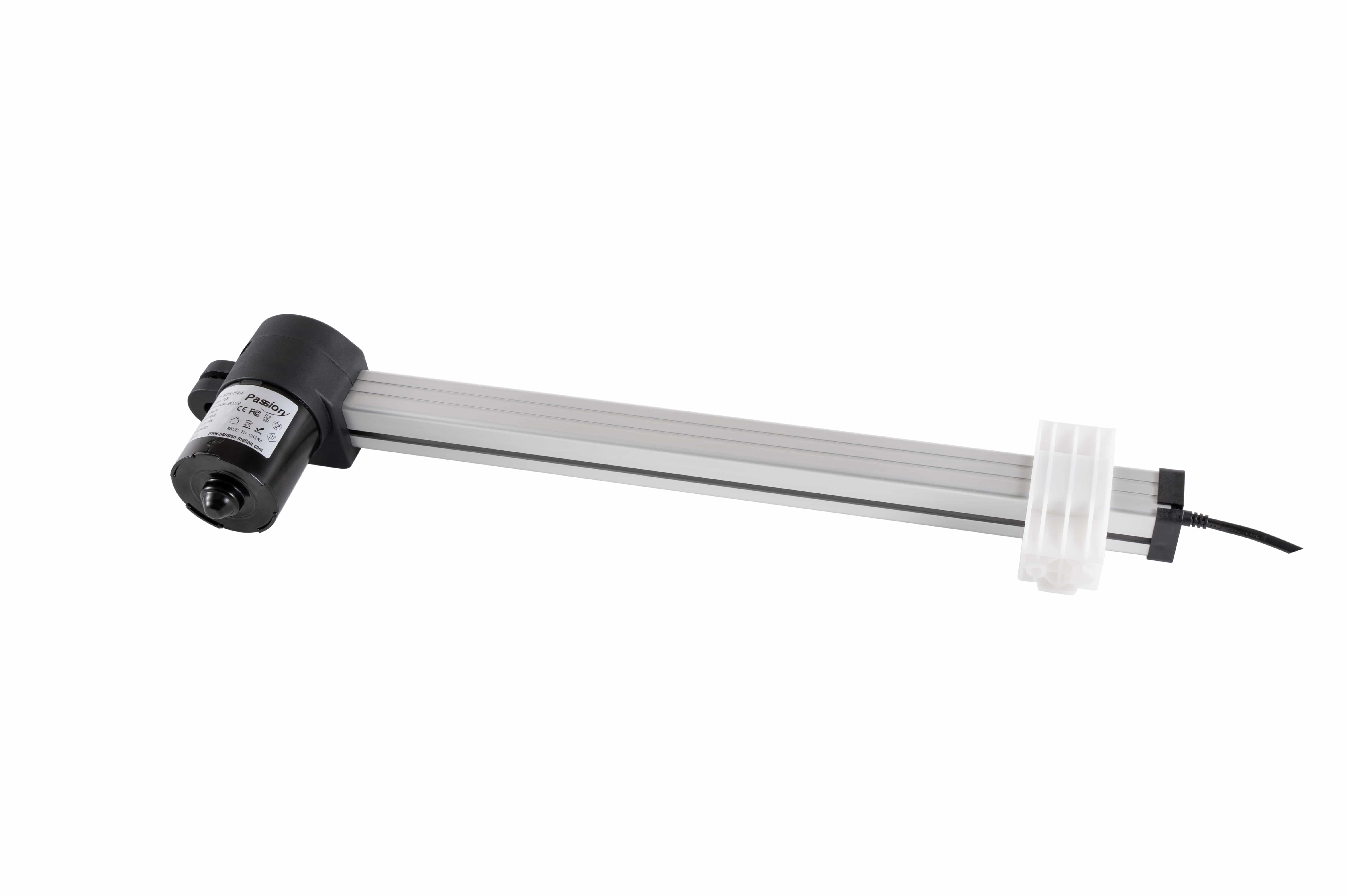
Mounting geometry should keep the actuator loaded along its intended axis while the structure carries unintended side loads and moments.
Check the candidate's actual mounting instructions and side-load limits. The correct guidance arrangement depends on actuator architecture; do not assume every product has the same allowable moment or transverse load.
10. Add Environment and Electrical Checks
Mechanical sizing can still fail at system level if the environment or electrical supply is wrong.
Before final selection, check:
- operating temperature;
- dust and water exposure;
- corrosion or chemicals;
- washdown or contamination;
- available voltage;
- steady and peak current;
- voltage drop through cables and connectors;
- controller current capacity;
- limit switches and end-of-travel behavior;
- position feedback;
- synchronization requirements;
- behavior after power loss.
These checks should use the specifications for the exact configuration, not generic family assumptions.
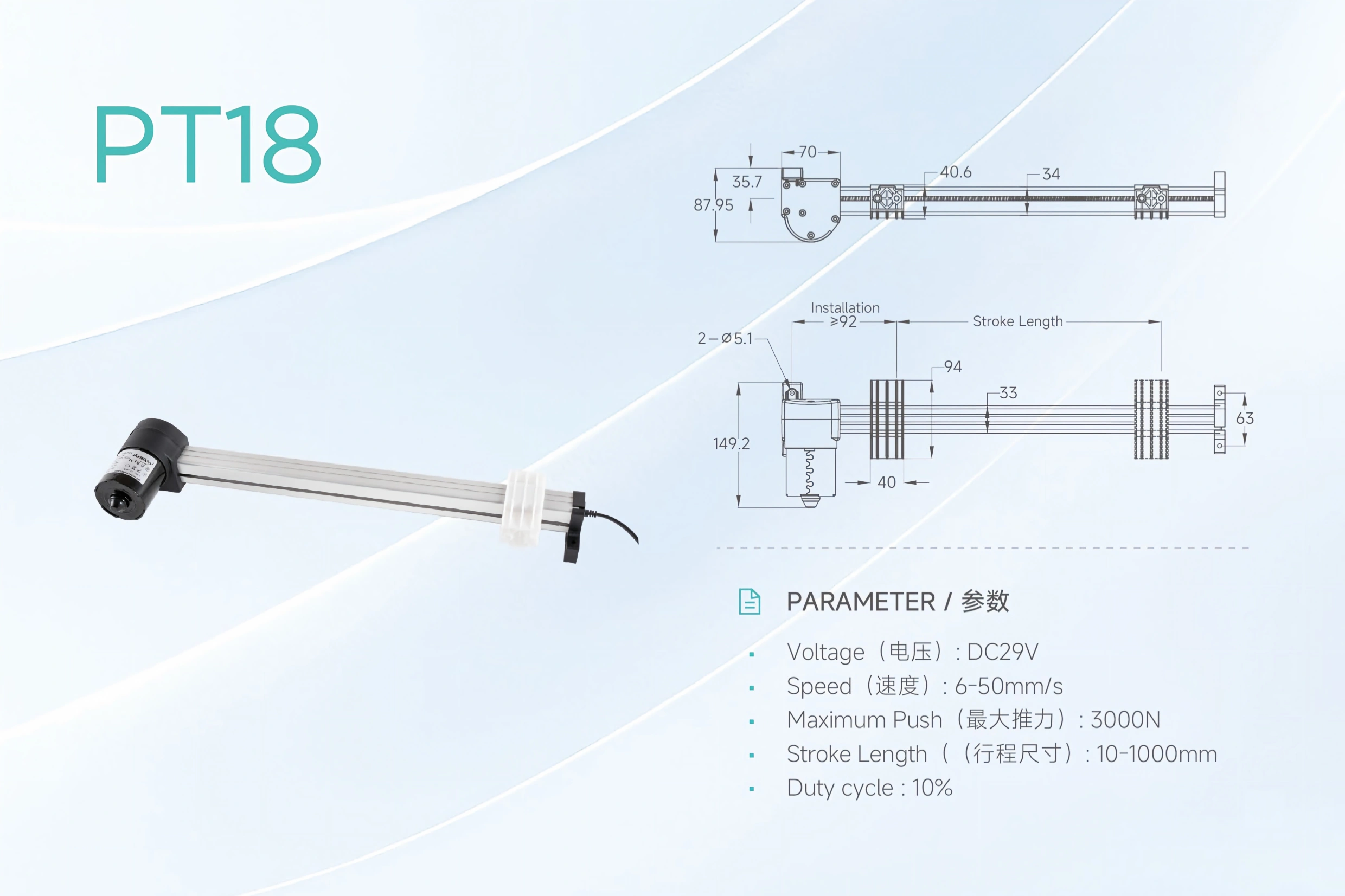
Final selection should verify force, loaded speed, stroke, duty cycle, and installed geometry together.
11. Final Configuration Validation Checklist
Before releasing a design, compare the calculated requirement against a real actuator configuration as one combined operating envelope.
Mechanical
- Required push and pull force at the worst load case
- Static/holding requirement where relevant
- Stroke
- Retracted and extended installed length
- Loaded speed
- Acceleration/deceleration requirement
- Buckling or critical-speed limits where applicable
- Mounting alignment and side-load limits
- Bracket, pin, and supporting-structure capacity
Thermal and Cycle
- Duty cycle at the actual load
- Run/rest pattern
- Ambient temperature
- Reversal frequency
- Worst-case thermal condition
Electrical and Controls
- Voltage range
- Running and peak current
- Controller and power-source capacity
- Cable voltage drop
- End-of-travel protection
- Feedback or synchronization if required
- Safe behavior after loss of power
Environment and Validation
- Required ingress protection
- Corrosion/chemical exposure
- Full-stroke clearance
- Worst-case payload and geometry test
- Start-up/breakaway condition
- Repeated-cycle validation
After the requirements are defined and checked, you can review the ServoCylMotion linear actuator range against the complete specification rather than selecting from force alone.
12. From Calculation to a Selection Brief
A good sizing result is not a single number. It is a compact engineering brief such as:
| Requirement | Example format |
|---|---|
| Motion | Vertical guided lift |
| Peak calculated axial force | 1.09 kN |
| Preliminary specified force | 1.64 kN using an illustrative 1.5 margin |
| Stroke | 300 mm |
| Loaded speed | 30 mm/s |
| Cycle | 30 extend/retract cycles per hour |
| Mounting | Pivoting ends, external guidance |
| Environment | Indoor, defined temperature range |
| Holding/safety | Project-specific requirement |
| Controls | Voltage, current, end limits, feedback as required |
That format makes assumptions visible and gives engineering, sourcing, and the actuator supplier the same starting point.
When you have these inputs, use the ServoCylMotion actuator sizing worksheet to organize the requirement and continue the sizing workflow. Treat the worksheet result as preliminary until the actual actuator configuration is checked against current product data and the real mechanism is validated.
Frequently Asked Questions
How do I determine the force a linear actuator needs?
Draw the free-body diagram for the worst credible load case. Add the force components that oppose the intended motion—such as gravity, mechanism resistance, acceleration, and external process force—then account for geometry and apply an explicit project-appropriate design margin.
Is payload weight equal to required actuator force?
Not necessarily. In a direct vertical lift at constant speed, weight may dominate the calculation. In horizontal, inclined, or hinged mechanisms, friction, acceleration, mounting angle, leverage, and other loads can make actuator-axis force higher or lower than payload weight.
How do I size a linear actuator for an incline?
Resolve gravity along the incline, add resistance, acceleration, and external forces, and calculate the force along the actual actuator line of action. If the actuator is not parallel to travel, use a complete free-body diagram because its perpendicular force component can also change bearing reactions and friction.
How do I calculate actuator force for a hinged lid?
Balance moments about the hinge. Calculate load torque from the load's perpendicular moment arm, then divide the required torque by the actuator's effective lever arm,
r × sin(φ)
. Repeat the calculation at multiple positions because the actuator angle changes during the stroke.
How much design margin should I add?
There is no universal value. The margin should reflect load uncertainty, shock, wear, environment, consequence of failure, company design rules, applicable standards, and the selected actuator's rating basis. Keep safety functions separate from ordinary design margin.
Does actuator stroke always equal load travel?
Only for simple aligned translation. In hinged or linked mechanisms, actuator stroke is the change in distance between its mounting points from one endpoint to the other.
Can I choose actuator force and speed independently?
Usually not. Motor, gearing, and screw characteristics couple force and speed. Verify the required force and loaded speed together for the same configuration.
Why does duty cycle matter if the actuator has enough force?
Because duty cycle is a thermal limit. A configuration can meet peak force yet overheat if the run time, cycle rate, load, or ambient temperature exceeds its permitted operating pattern.
Can two actuators split the load equally?
They can only be treated that way when the structure, load distribution, mounting, and synchronization support equal sharing. Real systems should be checked for imbalance and racking.
What should I verify after the preliminary sizing calculation?
Verify the real configuration's force, loaded speed, stroke, installed dimensions, duty cycle, environmental limits, mounting, current demand, control requirements, holding behavior, and performance under the worst credible mechanism condition.