Standing Desk Lifting System OEM Guide & Engineering Checklist
A B2B OEM engineering guide to define lifting architecture, travel, load, synchronization, power, wiring, validation, and release evidence.

A production-ready lifting system should be defined as an integrated motion platform before individual components are selected. For an OEM program, the essential inputs are the lifting-point layout, moving load and load distribution, required travel, loaded speed, duty pattern, mounting and guidance, synchronization behavior, power and wiring interfaces, validation conditions, and the documents needed to hold the configuration stable through production.
The engineering task is not to combine the largest force, longest travel, fastest speed, and highest power numbers from separate data sheets. Define one real operating point, then verify that the mechanical, electrical, control, and structural layers work together at that point.
Table of Contents
Start With the System Architecture, Not a Component List
The first engineering decision is the architecture of the moving platform. A rectangular two-point layout, a corner layout, and a four-point platform create different load paths, channel counts, wiring routes, synchronization problems, and structural demands even when their total moving mass is similar.
Define these items before comparing motion hardware:
- number and location of lifting points;
- top size, span, overhang, and accessory locations;
- moving mass and expected load distribution;
- whether motion points are mechanically coupled or independently driven;
- guidance and structural members that resist side load, racking, and twist;
- required control channels and motion relationship;
- available installation space for power, controls, and cabling;
- service access and replacement strategy.
A drive count by itself is not an architecture specification. The correct layout follows from geometry, load distribution, structural behavior, and the required motion sequence.
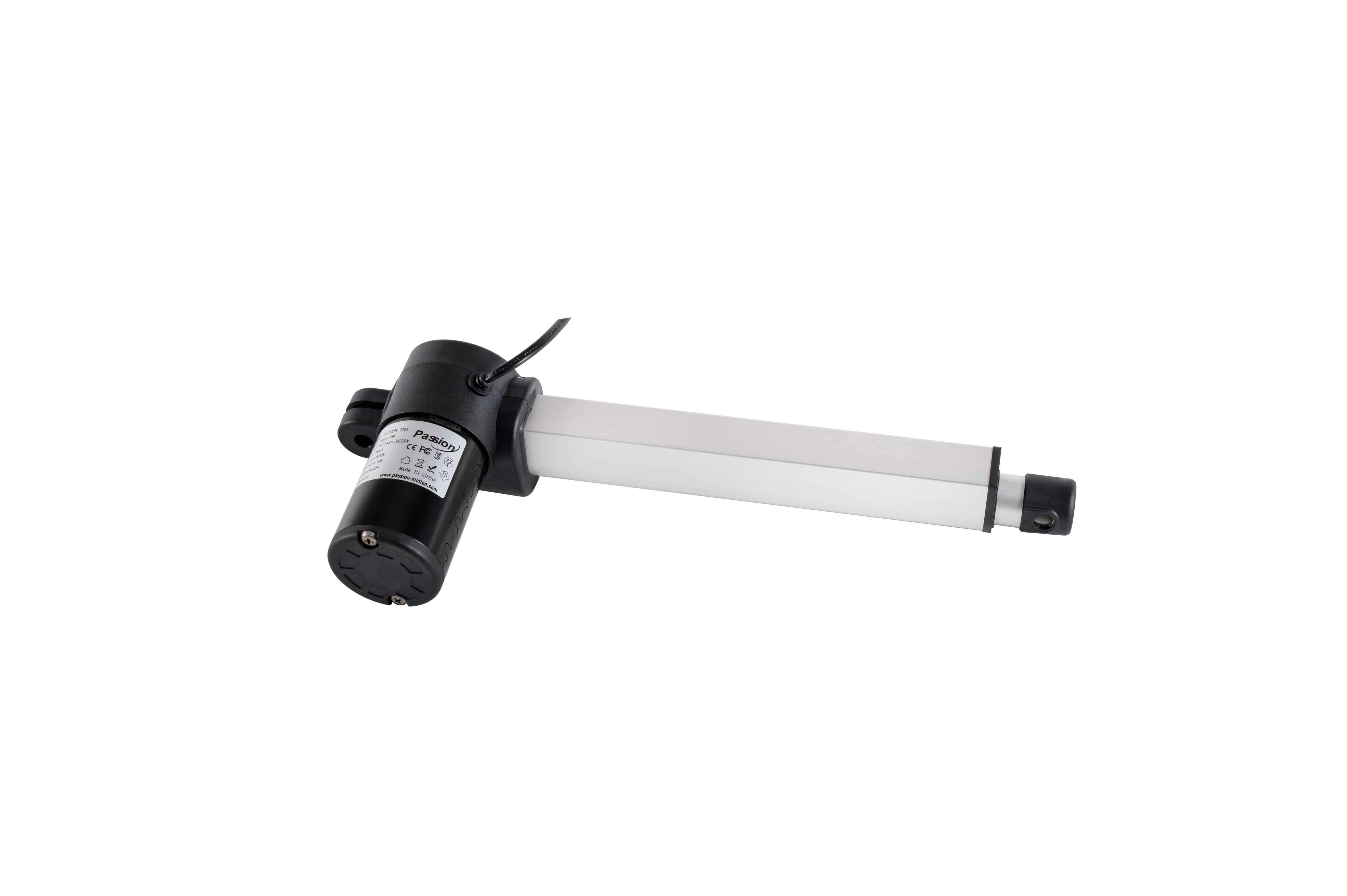
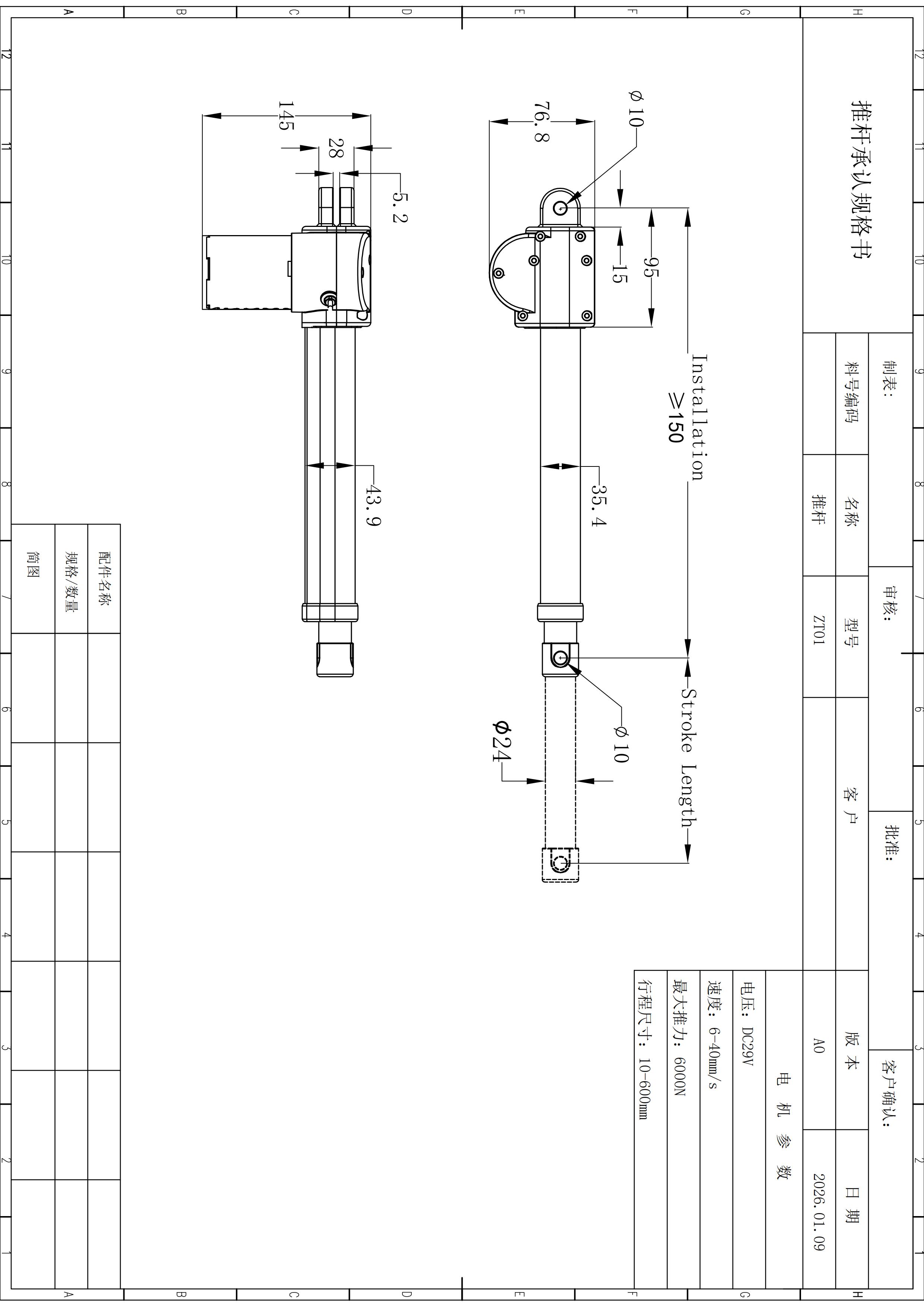
ServoCylMotion's PT and ZT families are locally documented as 29V candidate motion families. They should be treated as candidate ranges only after the system inputs are defined. Independent family maxima must not be combined into an assumed configuration.
Motion hardware should be evaluated against the defined load, travel, mounting, and control architecture rather than selected from one headline rating.
Translate the Product Envelope Into Travel and Installation Geometry
Required vertical movement is only one part of the geometry problem. The installed system also has a retracted package, extended package, mounting interfaces, top thickness, structural overlap, cable movement, and clearance zones.
Before design freeze, define:
- the lowest and highest required finished worksurface positions;
- the vertical travel needed between them;
- retracted and extended installation envelopes;
- top thickness and the stack-up between lifting element, structure, and worksurface;
- bracket locations, mounting-hole pattern, and fastener access;
- allowable overhang and equipment locations;
- cable slack, moving-loop path, bend allowance, and strain relief;
- keep-out zones for moving parts and nearby equipment;
- floor-leveling allowance and the condition of the support surface.
A component can have enough nominal travel and still fail the installed design because the retracted package is too large, the structure consumes usable movement, or cables and brackets interfere near an end position.
For standards-driven programs, do not copy a generic dimension from a web summary into the specification. The applicable adopted or authorized requirement should be checked for the target market and the exact product category.
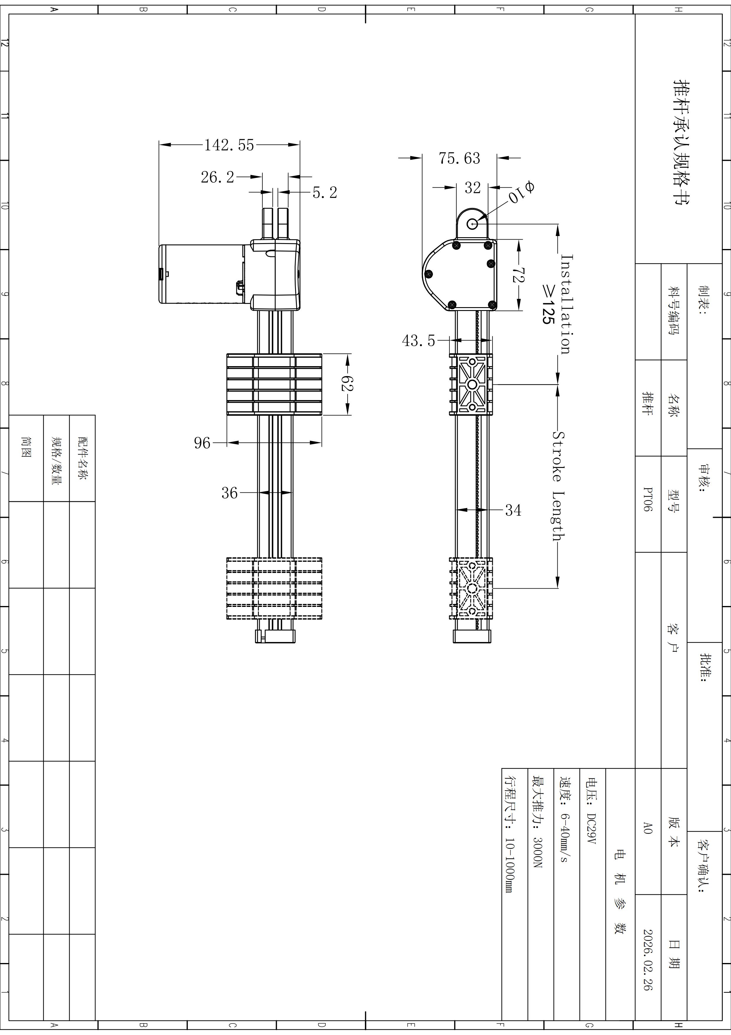
Different motion form factors can change packaging and mounting decisions, so the installed envelope should be checked before design freeze.
Define the Real Load and Performance Operating Point
Total mass is necessary, but it is not enough. A useful engineering load definition identifies what moves, where that mass is located, and how the load changes across normal and worst-case use.
Include:
- worksurface and moving structure;
- monitors, arms, computers, tools, and mounted accessories;
- future accessory allowance where the program requires it;
- edge and corner load cases;
- one-sided or otherwise uneven loading;
- center-of-gravity location and overhang;
- cable drag and other motion-dependent resistance;
- any service condition that changes the load path.
The engineering review should then pair that load definition with required loaded speed , not only an unloaded headline value. Record the intended working load, required transition time or velocity, supply condition, ambient condition where relevant, and the acceptable change in performance under asymmetric loading.
Specify duty as an operating pattern, not a vague adjective. Define consecutive moves, expected rest periods, cycles in the real use profile, and any commissioning or service sequence that can produce more frequent movement than normal operation.
Operating-Point Checklist
| Input | Define for the program | Why it changes the design |
|---|---|---|
| Moving load | Mass of the complete moving assembly and carried equipment | Determines force demand and structural loading |
| Load distribution | Normal, edge, corner, and uneven cases | Changes per-point force, moment, and synchronization demand |
| Required travel | Movement required in the installed product | Sets the motion envelope and packaging requirement |
| Loaded speed | Required motion rate at a stated load | Prevents no-load performance from being mistaken for working performance |
| Duty pattern | Consecutive moves, rest behavior, and realistic usage | Affects thermal and electrical margin |
| Guidance | How the structure controls side load and alignment | Influences friction, binding, stability, and component loading |
Specify Synchronization as Behavior You Can Test
"Synchronized" should not be the end of the control specification. A multi-point system needs a defined initialization process, coordinated-motion behavior, fault response, and recovery sequence.
Turn synchronization into explicit acceptance questions before the controller is frozen:
- How is the system initialized or calibrated?
- What position difference is acceptable for this project, and how will it be measured?
- What happens if load becomes uneven during travel?
- What happens if one channel stalls or becomes disconnected?
- What happens after a power interruption?
- Does the system require a reset or re-reference sequence?
- How are upper and lower software limits handled when they are part of the design?
- What should the user interface show during a fault?
- What evidence demonstrates recovery without leaving the structure in an unacceptable misaligned condition?
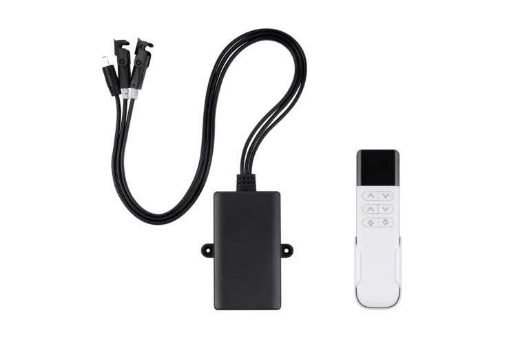
ServoCylMotion locally documents YK-06, YK-08, and YK-10 as synchronized two-, three-, and four-channel examples respectively. Those mappings are product-positioning references, not blanket compatibility approvals. The exact motion components, feedback interface, wiring, controller configuration, and mechanical platform still require project review.
For a deeper review of coordinated multi-point behavior, use the multi-motor synchronization engineering resource .
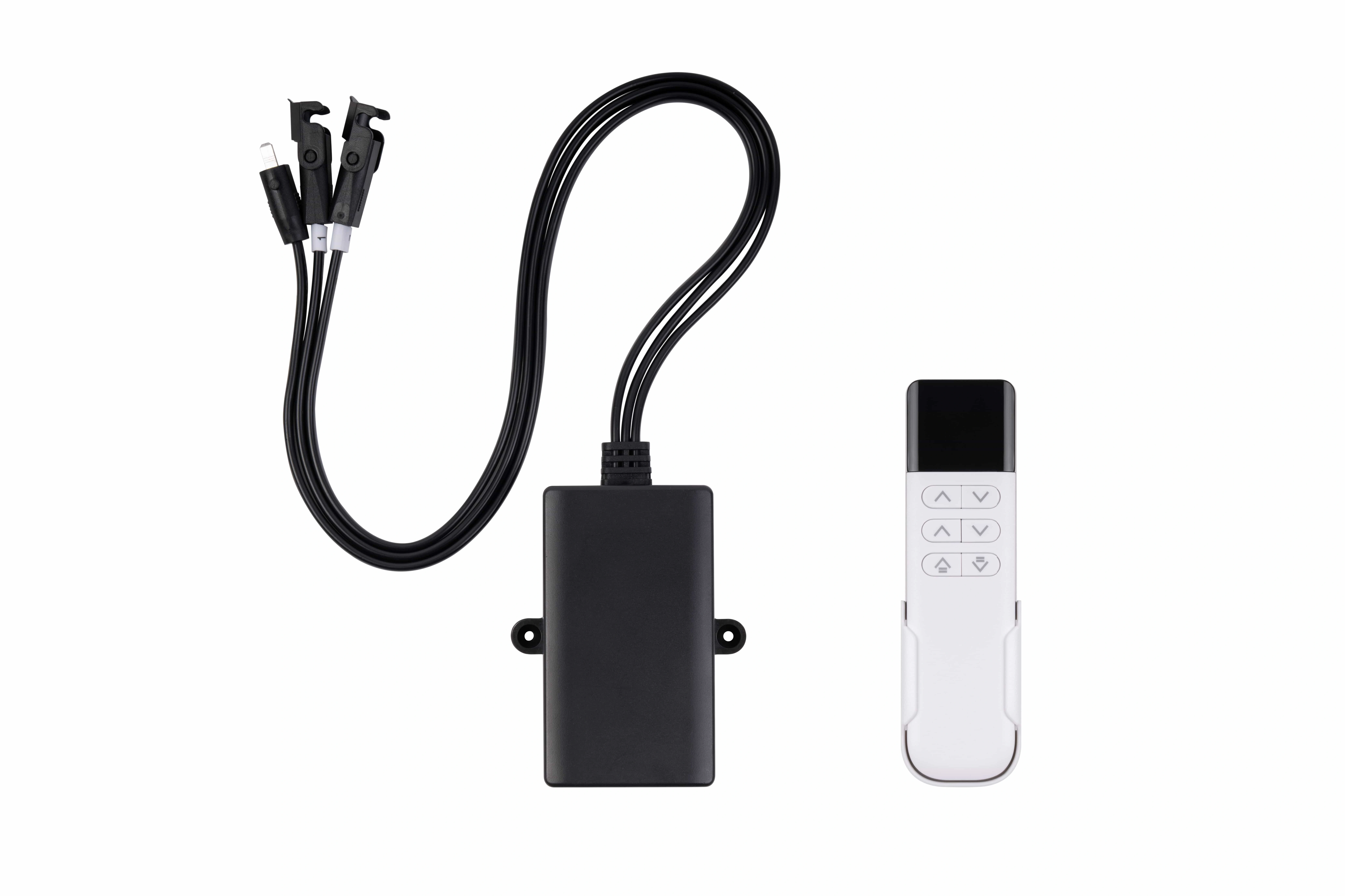
YK-06 is a locally documented two-channel synchronized example; final component pairing still requires configuration review.
Engineer Power, Connectors, and Wiring as One Interface Chain
Nominal voltage is only the first electrical check. A production system must also satisfy current demand, startup behavior, simultaneous channel operation, connector and polarity requirements, control interfaces, cable routing, and service constraints.
The local YK controller family is documented around DC 29V and 60–120W family-level power handling. ServoCylMotion also locally documents 29V power options in 1.8A (about 52W), 2.0A (58W), and 3.0A (87W) classes. These are documented platform examples, not automatic pairing approvals.
A shared 29V label does not establish compatibility. Verify:
- continuous and startup current demand;
- how many channels can start or run together;
- connector family and mating interface;
- pinout and polarity;
- motor and feedback interface;
- cable length and routing;
- moving-loop slack and strain relief;
- available service access;
- thermal behavior under the defined duty pattern.
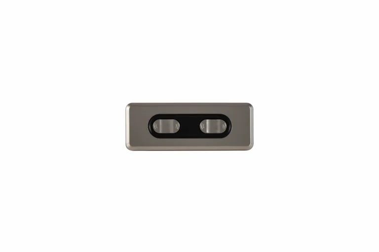
When the component chain is not already verified, use a system compatibility review before freezing connectors and wiring. The locally documented 29V power options can then be compared against the actual current and interface requirements.
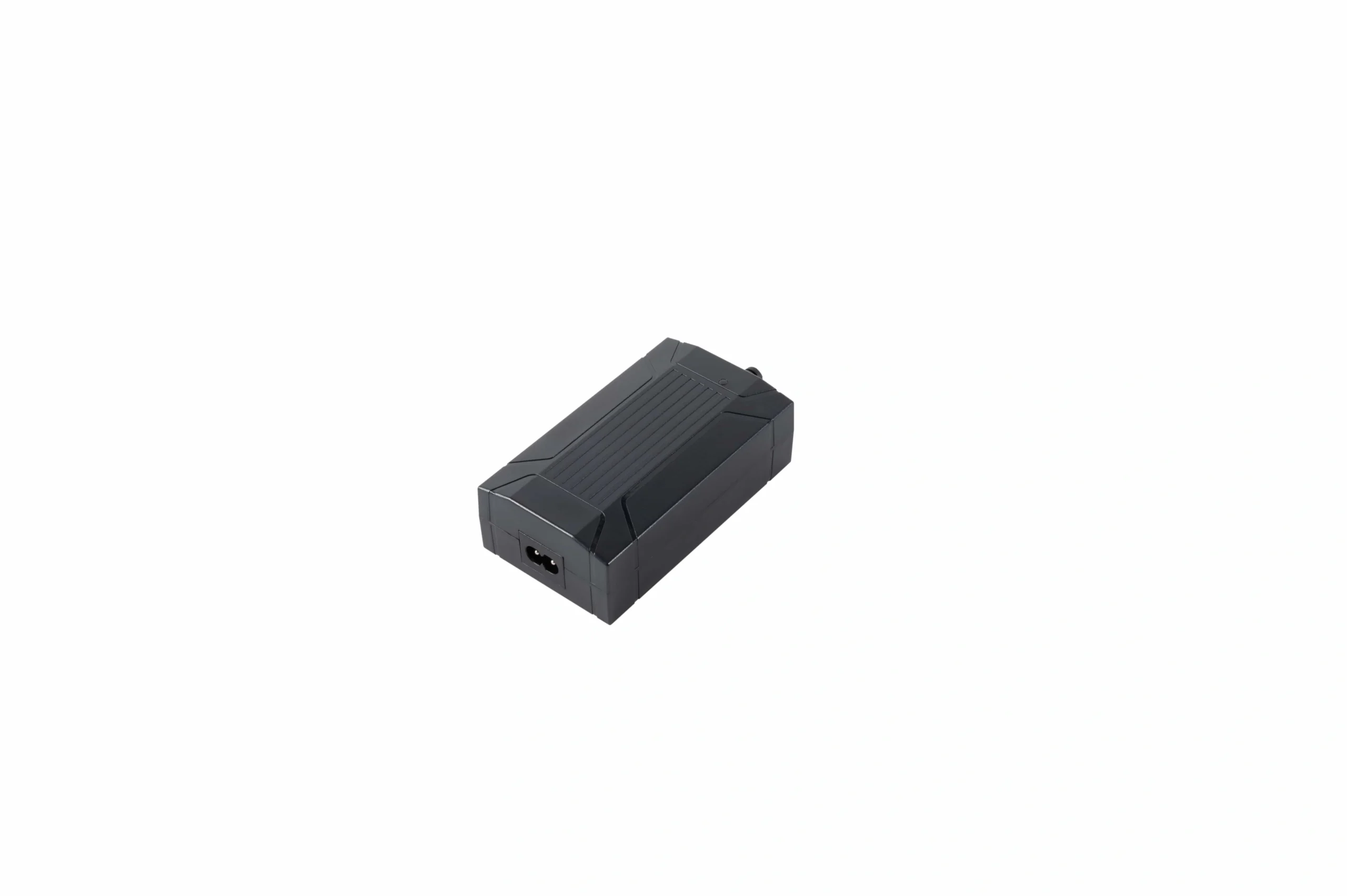
A 29V label alone does not establish system compatibility; current demand, startup behavior, connectors, polarity, and control interfaces still need to match.
Keep Structure and Stability in the Same Release Problem
A motion system can produce enough axial force and still perform poorly when the surrounding structure racks, twists, binds, or allows excessive movement at full extension.
Review the complete assembly across its travel, especially near the most extended position. Relevant checks include:
- guidance and rail overlap;
- cross-member stiffness;
- joint fit and fastener control;
- foot geometry and leveling;
- worksurface stiffness;
- top overhang and accessory placement;
- uneven loading;
- side loads and moments transferred into the moving hardware;
- cable forces that change through travel.
The mechanical structure should guide the moving platform so that motion components are not unintentionally used as the only resistance to side load or twist. If a design relies on a specific allowable moment or side-load capability, that value must come from controlled evidence for the exact configuration rather than a generic category assumption.
Build the BOM and Engineering Document Pack Together
A useful BOM is more than a part list. It should identify the system layer, the interface that must be controlled, and the evidence required to release that layer.
Motion-System Layer Map
| System layer | Typical scope | Define before release |
|---|---|---|
| Motion | Lifting elements, transmissions, drive hardware | Lifting points, moving load, travel, loaded speed, mounting |
| Control | Multi-channel controller, feedback interface, user control | Channel count, coordinated behavior, initialization, reset, fault response |
| Power | DC supply and mains interface | Voltage, continuous/startup demand, simultaneous loads, protections, installation |
| Frame interfaces | Rails, cross-members, feet, brackets, top attachment | Layout, mounting, stiffness targets, clearances, service access |
| Cabling | Motor, feedback, control, and power leads | Length, pinout, routing, bend allowance, strain relief |
| Validation | Functional, structural, electrical, cable, and repeat-cycle checks | Test load, duty profile, conditions, acceptance criteria |
The engineering document pack should identify at least:
- general arrangement and installation drawing;
- mounting-hole and keep-out information;
- load cases and load-position assumptions;
- wiring diagram, connector family, and pinout;
- controller and configuration identification;
- initialization, reset, and fault-recovery procedure;
- cable lengths and routing requirements;
- fastener and assembly-control information where applicable;
- test conditions and acceptance limits;
- controlled change process for components, wiring, and firmware;
- replacement or service compatibility rules.
This documentation allows engineering, sourcing, quality, assembly, and service teams to review the same controlled configuration instead of interpreting separate component descriptions differently.
OEM Engineering Release Checklist
Use this checklist before design freeze and again before production release.
| Design input | Define before design freeze | Why it matters | Evidence before release |
|---|---|---|---|
| Lifting-point architecture | Count, position, coupling method, channel need | Establishes load paths and coordination problem | Approved system layout and block diagram |
| Moving load | Complete moving mass plus accessories | Sets working force demand | Load list tied to the approved configuration |
| Load distribution | Normal, edge, corner, uneven cases | Affects per-point force, moment, and stability | Load-position drawing or test matrix |
| Travel and package | Required movement, retracted/extended envelope, clearances | Prevents packaging and interference failures | Installed-envelope drawing and full-travel check |
| Loaded speed | Required performance at a defined working load | Separates working performance from no-load values | Loaded-motion test result |
| Duty pattern | Consecutive moves, rest behavior, expected usage | Affects thermal and electrical margin | Duty-based functional/thermal test |
| Guidance and structure | Rails, overlap, stiffness, feet, joints, top interface | Controls side load, racking, and stability | Structural review and stability test |
| Synchronization | Initialization, mismatch criterion, fault and recovery behavior | Makes coordinated motion measurable | Synchronization and recovery test record |
| Power | Supply class, continuous/startup demand, simultaneous operation | Prevents voltage-only selection | Power budget and loaded current result |
| Connectors and wiring | Pinout, polarity, cable lengths, moving routes | Prevents interface and cable-motion failures | Approved wiring diagram and cable inspection |
| Controls | Channel count, user functions, limits, reset behavior | Defines expected motion and recovery | Configuration record and functional test |
| Environment | Temperature, humidity, dust, cleaning, vibration as applicable | Can change electrical and mechanical performance | Project-specific environmental evidence |
| Documentation | Drawings, configuration IDs, procedures, test criteria | Supports repeatable production and service | Controlled document pack |
| Change control | Rules for hardware, cable, firmware, and substitution changes | Prevents unreviewed changes to a qualified system | Revision and approval record |
Validate the Complete Assembly Before Production Release
Component-level testing is useful evidence, but it does not automatically qualify a different complete assembly. Validation should use the intended structure, worksurface, accessories, wiring, controller, supply, and motion components.
A practical release plan can include:
- dimensional inspection and full-travel clearance;
- motion at the intended working load;
- loaded speed and current measurement;
- stability at low, intermediate, and high positions;
- uneven-load cases where relevant;
- initialization, synchronization, reset, and fault recovery;
- power-interruption behavior;
- motor, controller, connector, and supply thermal checks under the intended duty pattern;
- cable flex, routing, strain relief, and connector retention;
- repeated cycling under defined conditions;
- obstruction-response testing when that behavior is part of the verified configuration;
- production end-of-line checks tied to acceptance criteria.
A test should identify the load, position, operating condition, sample configuration, and pass/fail limit. Without those conditions, a cycle count or performance label is difficult to transfer into an OEM release decision.
Standards: Keep Guidance, Product Testing, and Dimensions Distinct
Standards and guidelines should be mapped to the role they actually play in the target program.
BIFMA G1 is furniture ergonomics guidance. It should not be presented as the same thing as a product test standard or as a blanket product certification.
ANSI/BIFMA X5.5 provides desk and table product testing context for safety, durability, and structural performance. The exact applicable edition, scope, test program, and evidence should be confirmed for the product being released.
EN 527-1 addresses dimensional requirements for office work tables. Specific dimensions should be checked against an authorized text and the version adopted for the target market rather than copied from a secondary summary.
For a multi-market program, create a compliance matrix that states the destination market, applicable requirement, evidence owner, document revision, and any configuration dependency. Do not assume that a generic standards reference proves the complete product meets every requirement.
Frequently Asked Questions
What should an OEM define before choosing the lifting architecture?
Define the lifting-point layout, complete moving load, load distribution, required travel, loaded speed, duty pattern, mounting and guidance, coordinated-motion behavior, power and wiring interfaces, validation conditions, and required documentation. Component selection should follow those inputs.
How should the number of lifting points be chosen?
Base the decision on surface geometry, span, load distribution, structural behavior, and the required motion relationship. The number of drive channels is a consequence of the architecture, not a substitute for defining it.
Why is total load capacity not enough?
The same total mass can create different demands when it is concentrated near an edge, offset from the center, or distributed unevenly. Those conditions change per-point loading, bending moment, structural deflection, and synchronization behavior.
What should a synchronization requirement contain?
It should define initialization, the project-specific acceptable mismatch, uneven-load behavior, stalled or disconnected-channel response, power-loss recovery, reset behavior, and the test method used to verify those requirements. Do not assume a generic tolerance that is not supported by the exact configuration.
Does matching 29V automatically make components compatible?
No. Current demand, startup behavior, simultaneous operation, connector and polarity, control or feedback interface, cable configuration, and the selected motion hardware must also match.
What should be tested before production release?
At minimum, test full travel, working-load motion, loaded speed/current, stability, relevant uneven-load cases, coordinated-motion and recovery behavior, thermal conditions, moving cables, repeated cycles, and the defined production checks. Add project-specific structural, environmental, and safety tests as required.
References
Review the Complete Motion Solution
If the architecture, operating point, control behavior, and validation requirements are defined, the next step is to review the complete standing-desk motion solution against that controlled requirement set.