Standing Desk Motion System BOM: What OEM Teams Should Freeze Before Production
Build a revision-controlled standing desk motion system BOM covering lifting hardware, control, power, feedback, cables, regionalization, and approved alternates.

A standing desk motion system BOM should do more than list parts. For an OEM program, it should define the released system configuration : which lifting mechanisms, controller, user interface, DC source, AC-input hardware, cables, feedback signals, firmware parameters, and optional modules are approved to work together.
That distinction matters because a part can look electrically plausible and still be incompatible. A matching connector shell does not prove the pinout is the same. A matching nominal voltage does not prove the controller can supply the required current. A keypad with the same buttons does not prove the protocol or firmware is compatible.
Suppliers such as TiMOTION and LINAK present desk-motion solutions as coordinated systems or kits, while replacement-control pages such as UPLIFT's make model and configuration distinctions explicit. The useful OEM lesson is simple: freeze interfaces, not just component names .
Table of Contents
What a motion-system BOM actually controls
A practical BOM for a powered height-adjustable desk usually sits at the boundary between mechanical design, electrical design, firmware configuration, sourcing, assembly, test, and after-sales service.
At minimum, the released record should answer five questions:
- What moves? Which lifting mechanisms or motor/gear assemblies are used, and how many?
- What controls them? Which controller channels, feedback inputs, and motion parameters are required?
- What powers the system? Is the design based on an integrated AC-input control box or an external low-voltage DC source?
- How are components connected? Which connectors, pinouts, cable lengths, conductor sizes, and harness routes are approved?
- Which revision is valid? What hardware, firmware, parameter file, regional input configuration, and approved alternates belong to the released build?
If those fields are missing, the BOM is a procurement list rather than a reproducible engineering definition.
For projects that need a broader fit check before release, ServoCylMotion's system compatibility resource is the more appropriate next step than assuming parts from different families will interchange.
OEM motion-system BOM table
The table below is the core release checklist. It separates a system into functional lines and shows which interface fields should be frozen before production.
| BOM line | Function | Usually required? | Fields to freeze before release |
|---|---|---|---|
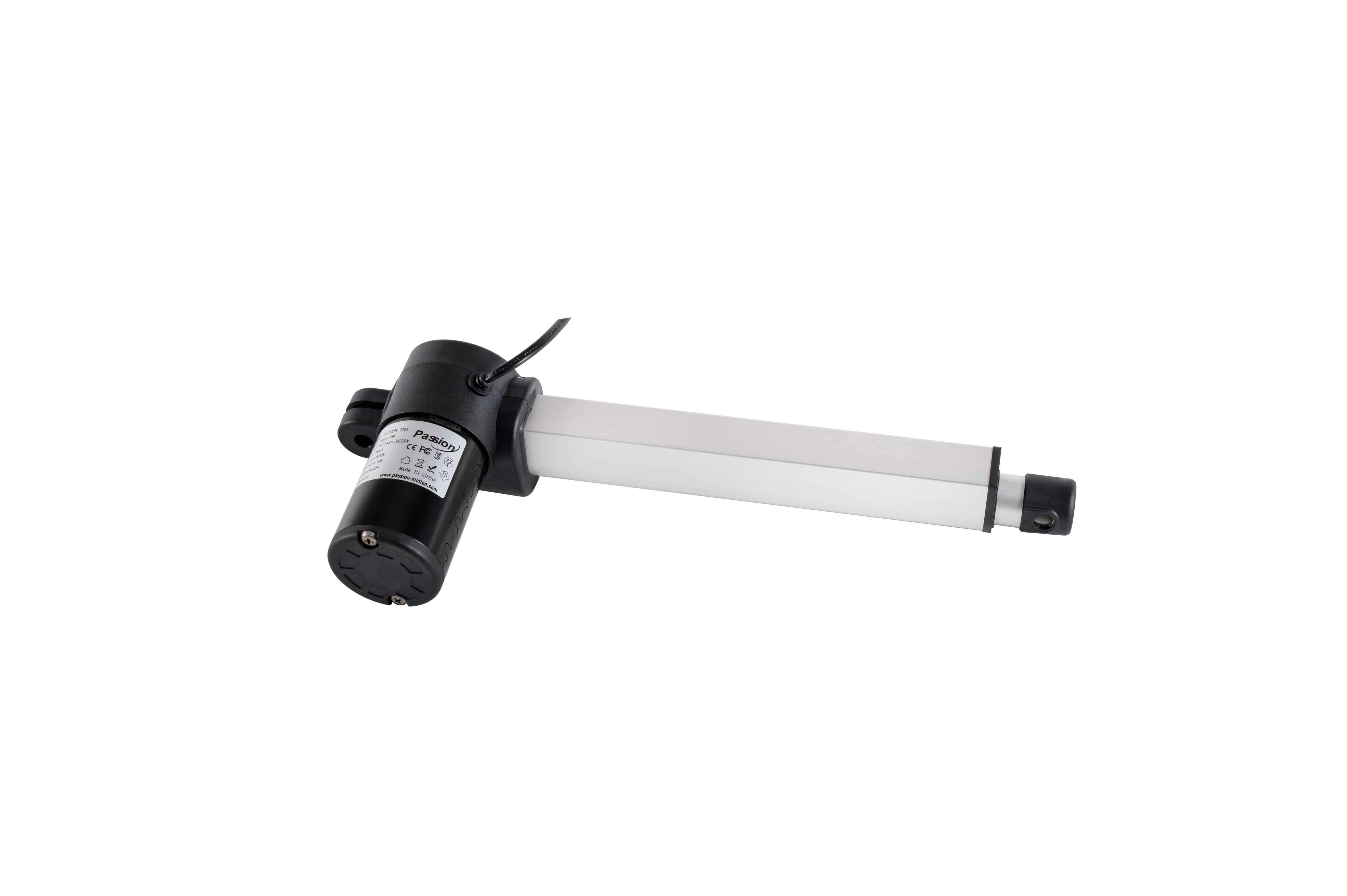
| Lifting mechanisms / motor-gear units | Produce vertical travel | Yes | family or exact part, quantity, stages, stroke, mechanical interface, load/duty requirement, motor electrical requirement, feedback type, connector, channel identity |
| Control box / motion controller | Drives motors, coordinates channels, stores logic/parameters | Yes | input architecture, channel count, motor mapping, supported feedback, current budget, handset interface, accessory ports, hardware revision, firmware, parameter-set ID |
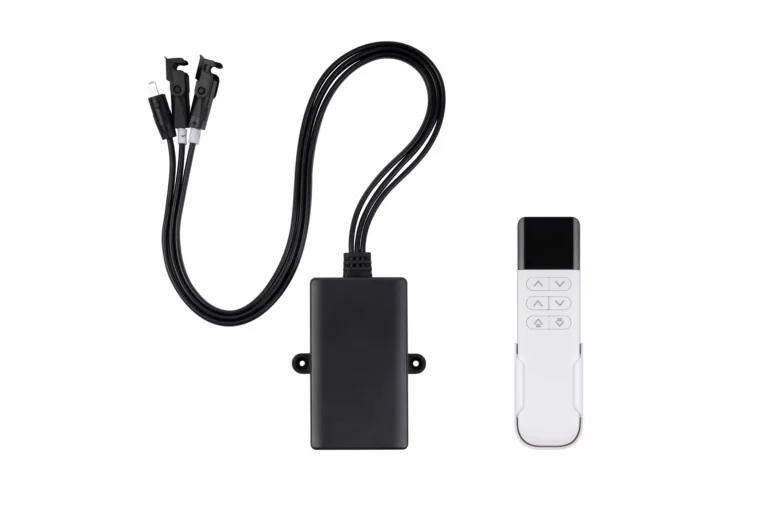
| Handset / desk panel | User commands, reset, homing, display, memory or lock functions | Usually | connector, supply, protocol, supported controller revision, button functions, display/units, reset sequence |
| External DC source | Supplies low-voltage DC when architecture requires it | Conditional | nominal output, continuous and peak current, connector, polarity, protection behavior, cable length, thermal limits |
| Regional AC cord / input lead | Connects the system to local mains | Yes for cord-connected systems | destination region, plug/inlet type, voltage/current rating, conductor configuration, grounding requirement, length, strain relief |
| Motor / feedback cables | Carry motor power and position/safety signals | Yes | connector family, gender/keying, pinout, conductor count, gauge, shielding, length, current rating, bend radius, channel label |
| Extension cables / frame harness | Routes interfaces through the frame | Conditional | branch topology, mating connectors, pin-for-pin mapping, gauge, length, shielding, clips/grommets, service loop, routing |
| Sensors / anti-collision inputs | Support obstruction or position/safety functions | Architecture-dependent | sensor type, controller input, connector, threshold/calibration, firmware enablement, failure behavior |
| Wireless / accessory modules | Add remote, app, charging, or auxiliary functions | Optional unless required by the product specification | protocol, controller port, power draw, pairing, firmware, regional radio requirements |
| Motion-critical brackets / fasteners | Maintain alignment and structural interfaces | Yes where load-bearing | drawing revision, hole/thread pattern, material/grade, torque, locking method, quantity |
| Configuration / release records | Make the system repeatable and serviceable | Yes | supplier part IDs, hardware revisions, firmware, parameter file/checksum, wiring diagram, approved alternates, work instruction, test record |
Control and interface components should be frozen as part of the released system BOM, not selected independently.
The key point is not that every desk uses every line. The key point is that each released product variant should make the required, conditional, and optional lines explicit.
Map the power and signal path before freezing the BOM
A BOM becomes easier to audit when the team first draws a simple power-and-signal path.
A common external-DC architecture can be represented as:
regional AC outlet → AC-input cord → DC source → motion controller → motor/feedback cables → lifting mechanisms
The command path then adds:
handset or wireless input → controller logic → motor drive → feedback → controller correction
An integrated AC-input controller collapses the external DC-source step, but the engineering questions remain the same. The team still has to verify mains input, motor power budget, feedback, channel mapping, controller configuration, and user-interface compatibility.
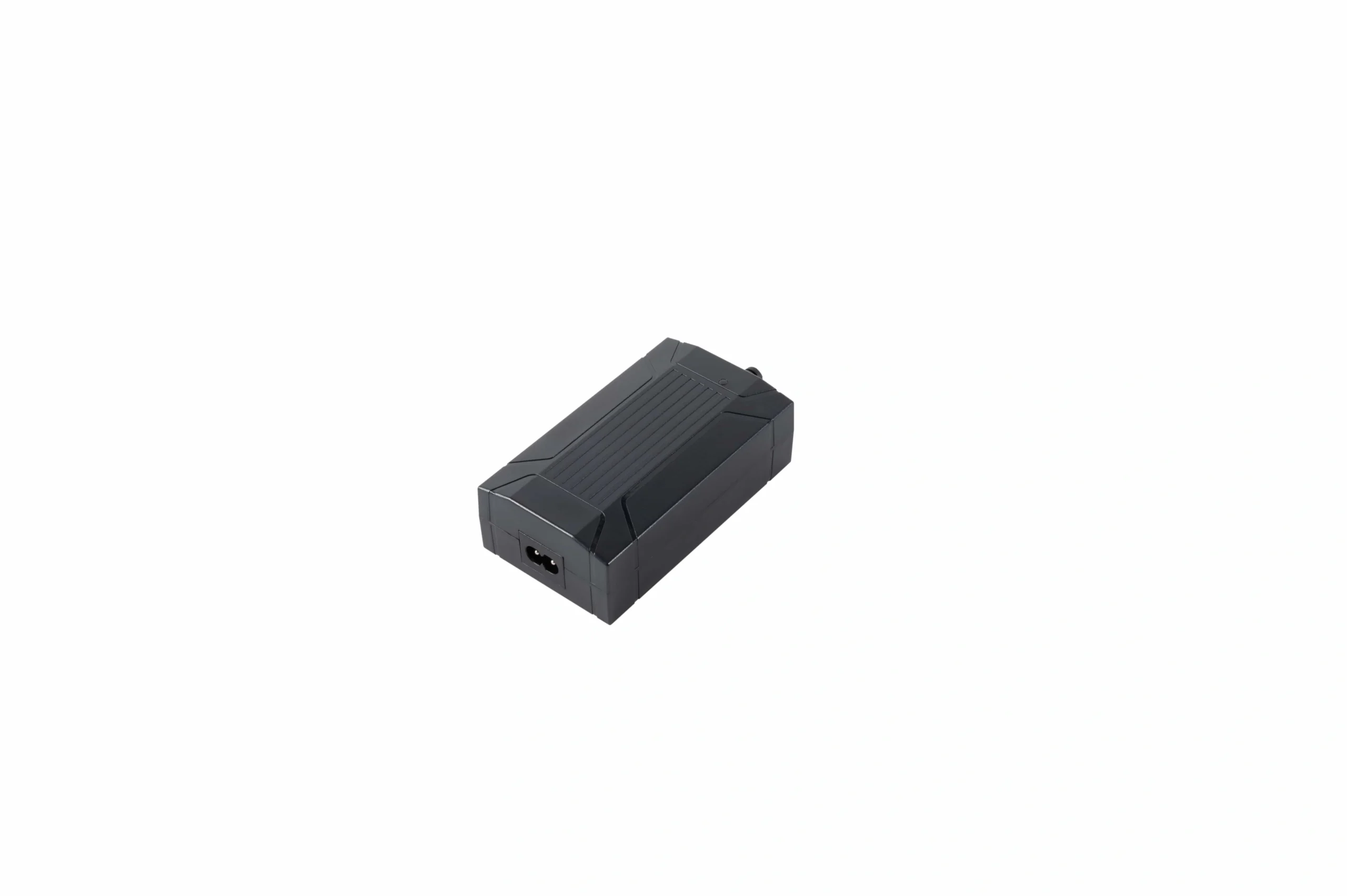
External-DC architectures require the supply, controller input, connector, polarity, and current budget to be released together.
Freeze power as a budget, not a label
Do not stop at a nominal voltage. Record:
- allowable input range;
- continuous current requirement;
- peak or startup current;
- total system power budget;
- per-channel demand where relevant;
- current limiting and protection behavior;
- connector current rating;
- polarity;
- thermal derating;
- duty-cycle assumptions.
For a 29 V standing desk power system, for example, the nominal DC value is only one field in the compatibility record. The controller input range, motor demand, peak current, connector, and harness must still be verified for the actual configuration.
This is also where sourcing teams should avoid substituting a supply because the plug “fits.” Electrical and control interfaces must be validated as a set.
Freeze motor count, channel mapping, and feedback together
A two-motor frame is not defined only by having two motors. The controller also needs the correct number of channels and the correct feedback scheme for the motion architecture.
Freeze:
- physical motor or lifting-unit count;
- controller channel count;
- channel-to-leg assignment;
- whether channels run synchronously, independently, or in a master/follower arrangement;
- feedback type on each channel;
- expected feedback polarity/direction;
- permitted mixed-component combinations;
- reset or initialization behavior;
- synchronization tolerance and error handling.
For projects where the difference between linked and independent motion is a design decision, see the dedicated multi-motor synchronization capability .
Feedback is a compatibility interface
Hall pulses, incremental encoders, absolute feedback, current-based sensing, and dedicated collision sensors are not interchangeable concepts.
The BOM or associated interface matrix should identify:
- feedback technology;
- sensor supply;
- signal count;
- direction convention;
- shared versus separate cable conductors;
- reference ground;
- controller expectation;
- homing or initialization method.
If a replacement motor has the same mechanical dimensions but a different feedback scheme, it should be treated as a new engineering combination until validated.
Connector shape is not a pinout
This is one of the most common sources of avoidable integration failure.
For each electrical interface, freeze:
- connector manufacturer/family where known;
- plug/receptacle gender;
- number of positions;
- keying and latch;
- contact rating;
- exact pin-by-pin function;
- motor polarity;
- feedback supply and signal pins;
- communication pins for the handset or accessories;
- shield or earth treatment;
- cable exit orientation.
The visible housing should never be the approval criterion.
The same logic applies to extension cables. A mechanically mating cable can still introduce a wrong pin map, inadequate conductor size, excessive voltage drop, poor feedback integrity, or a routing problem.
Treat cable construction and routing as BOM data
Cables are often under-specified because they appear to be passive parts. In a moving desk frame, they affect both electrical performance and mechanical reliability.
Record:
- finished length and tolerance;
- conductor count;
- conductor gauge;
- voltage/current rating;
- shielding or twisted-pair requirement;
- overmold and strain relief;
- minimum bend radius;
- moving service-loop requirement;
- clip and grommet positions;
- separation between mains and low-level signal wiring;
- pinch and abrasion protection.
For regional or project-specific harness requirements, power cable customization is the appropriate commercial bridge after the engineering requirements are defined.
Firmware and parameter files belong in the released configuration
A controller part number alone may not reproduce the same desk behavior if the firmware or parameter set changes.
The release package should identify, where applicable:
- controller hardware revision;
- firmware version;
- bootloader or programming compatibility;
- parameter-set revision;
- channel map;
- speed and acceleration limits;
- current limits;
- upper and lower travel limits;
- anti-collision enablement or sensitivity;
- reset and homing logic;
- display or handset functions;
- error-code behavior;
- configuration-file checksum.
This is especially important when procurement approves an alternate controller or when a supplier revises electronics without changing the mechanical envelope.
Separate mandatory, conditional, and optional lines
A useful BOM should distinguish required to move , required for a particular architecture , and required only for a committed feature .
Normally mandatory
A functioning electric desk motion architecture generally needs:
- lifting hardware;
- controller;
- a valid power path;
- motor and required feedback conductors;
- a command or commissioning interface;
- motion-critical mounting hardware;
- wiring and reset/commissioning documentation.
Conditional
These may be required depending on frame geometry and system architecture:
- extension cables;
- multi-branch harnesses;
- external sensors;
- service/programming cables;
- additional controller channels;
- master/follower links;
- specialized brackets.
Optional only when the product requirement allows omission
Examples can include:
- memory controls;
- display functions;
- app connectivity;
- RF remote control;
- USB charging;
- auxiliary sensors;
- cosmetic cable-management accessories.
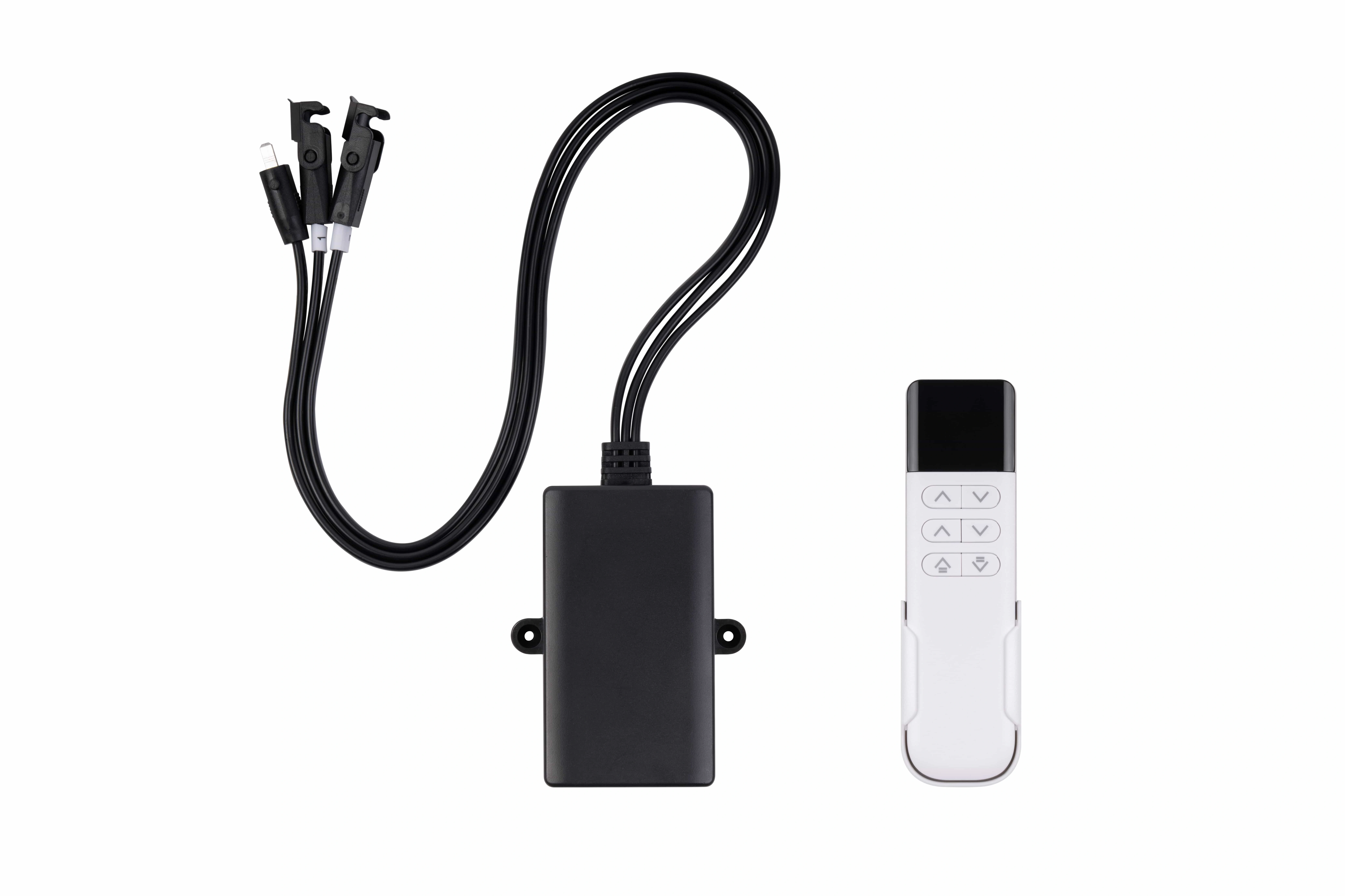
A wireless command module is optional only when the released product requirement does not depend on that function.
An accessory stops being optional when the marketed or contracted function depends on it. If wireless command is promised in the released specification, the wireless module and its controller compatibility become required lines for that variant.
Regionalize the AC-input side as a controlled BOM variant
Destination-market power hardware should not be selected at the end of the project as a packaging detail.
Freeze:
- destination country or region;
- mains input requirement;
- plug and inlet configuration;
- conductor/grounding arrangement;
- cord length;
- strain relief;
- labeling or documentation requirements;
- controller or DC-source input compatibility.
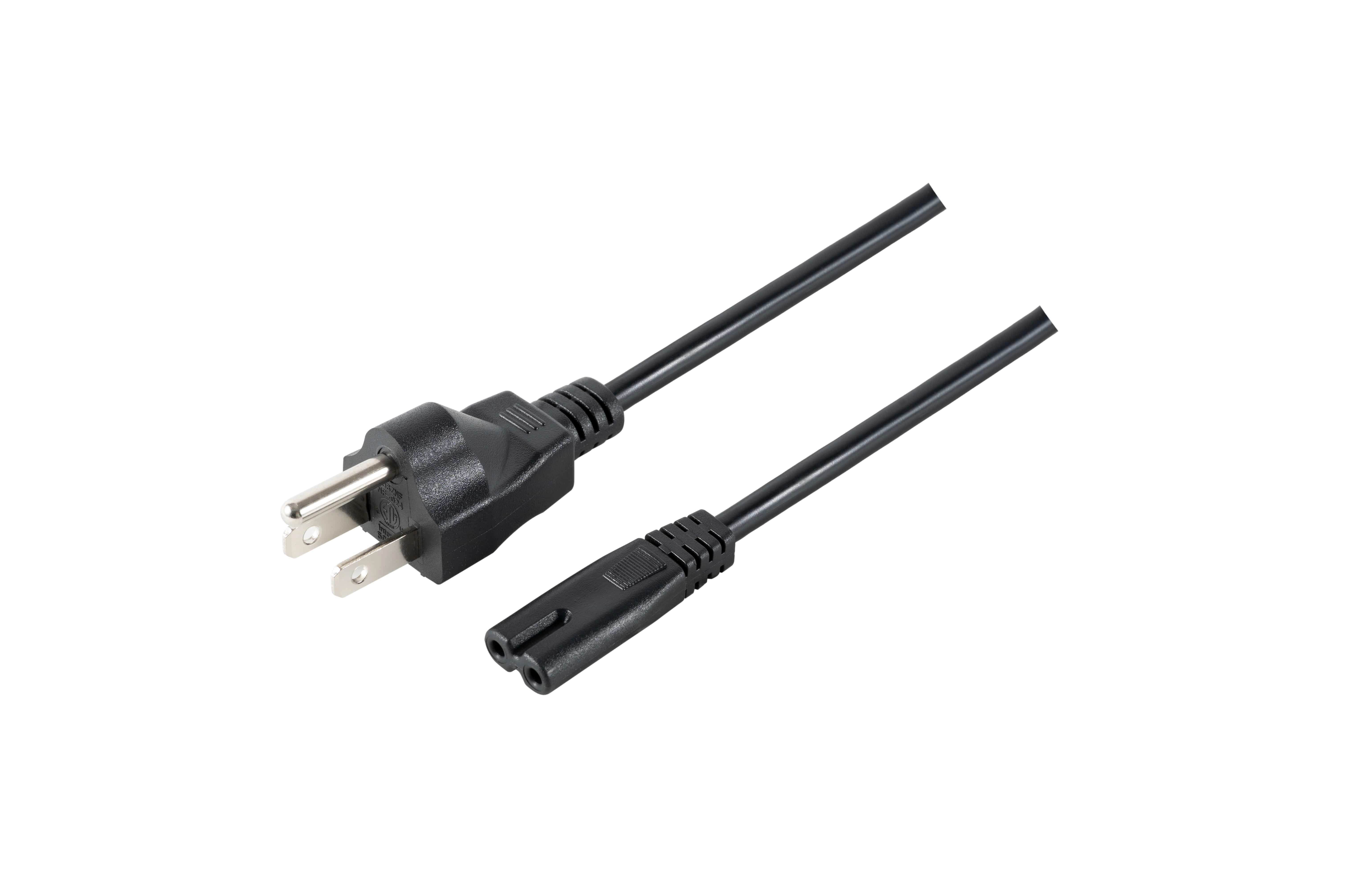
Regional AC cord and grounding requirements belong in the destination-market BOM variant.
The same controller family may have different regional input configurations, and not every frame/control variant is necessarily offered in every input version. Treat the market-specific power path as a released variant that must be validated with the rest of the system.
For the commercial application context—rather than the BOM methodology—see ServoCylMotion's standing-desk solution page .
Common BOM failure modes
1. Mixing components from different system families
Each item looks plausible on its own, but the controller, lifting hardware, and UI use different feedback, protocols, or parameter conventions.
Prevention: freeze the validated combination, not a shopping list of individually acceptable parts.
2. Matching only the connector housing
The cable mates mechanically but uses a different pinout or contact rating.
Prevention: release a pin-level interface drawing or wiring diagram.
3. Ignoring channel count or channel order
A controller has “multiple outputs,” so the team assumes any channel can drive any leg.
Prevention: record motor count, channel mapping, allowed topology, and initialization behavior.
4. Treating nominal voltage as the compatibility test
The supply label matches, but the current budget, connector, polarity, or peak demand does not.
Prevention: verify the full power budget and interface.
5. Substituting cable length without revalidation
A longer cable introduces voltage drop, signal integrity risk, routing problems, or strain.
Prevention: approve cable construction and finished length as part of the BOM.
6. Changing electronics without freezing firmware
The hardware part looks unchanged, but behavior differs because parameters or firmware changed.
Prevention: record revision and configuration identifiers.
7. Calling an alternate “equivalent” without validation
A supplier substitute meets one headline specification but differs at an interface.
Prevention: use an approved-alternate process with documented equivalence and test evidence.
RFQ and release checklist
Before requesting a production quotation or approving a new revision, send an interface package rather than a list of component names.
A useful RFQ should include:
- target frame configuration and motor count;
- lifting-unit mechanical requirements;
- controller channel count and topology;
- required feedback method;
- power architecture and current budget;
- connector and pinout requirements;
- cable lengths, gauge, and routing constraints;
- handset functions and protocol requirements;
- synchronization, reset, and homing behavior;
- sensor or anti-collision requirements;
- regional AC-input configuration;
- firmware or parameter-set requirements;
- approved-alternate rules;
- wiring diagram and inspection/test expectations;
- revision-control and change-notification requirements.
If the project is ready for a component-level compatibility review, send the draft BOM and interface matrix through ServoCylMotion contact before the production revision is frozen.
FAQs
What is the difference between a parts list and a motion-system BOM?
A parts list says what is purchased. A motion-system BOM should also define the interfaces and revisions that make those parts a validated system: electrical limits, channel mapping, feedback, connectors, wiring, firmware/parameters, and regional variants.
Is matching the nominal DC voltage enough to approve a replacement?
No. Also verify current capacity, peak demand, connector and pinout, polarity, feedback, controller channel mapping, protocol, cable construction, and firmware/parameter compatibility.
Should the controller and handset be frozen as a pair?
They should be frozen as compatible interfaces. Record the controller revision, handset protocol, connector, required functions, and any firmware dependency rather than assuming that a similar-looking panel is interchangeable.
Can an extension cable be substituted if both ends fit?
Not safely on connector fit alone. Verify pin mapping, conductor size, current capacity, feedback integrity, cable length, shielding, bend radius, and routing.
How should regional AC cords be handled?
Treat the destination-market cord and input configuration as controlled BOM fields. Confirm the local mains requirement, plug/inlet arrangement, grounding approach, controller or DC-source input, and documentation for the released market.
When is a wireless module optional?
It is optional only when the released product requirements can be met without wireless control. If wireless operation is part of the committed configuration, the module, protocol, pairing behavior, and controller compatibility become required BOM data.
What information should be recorded for an approved alternate?
Record the exact alternate part identity, revision, electrical/mechanical interface equivalence, firmware or parameter impact, validation evidence, approval date, and the change record that authorizes the substitution.