How Electric Actuator Control Works: Wiring, Direction, Limits, and Protection
Learn how electric actuator control electronics switch motor direction, handle limit inputs and feedback, connect power, and protect a basic motion circuit.

Electric actuator control electronics sit between a command source and the motor. Their basic job is to decide when the motor should run, in which direction, when it should stop, and what conditions should block motion .
In the simplest two-wire DC arrangement, extend and retract are produced by reversing motor polarity. More capable systems add relays or semiconductor drives, command inputs, current protection, feedback signals, multiple channels, status outputs, and communication interfaces.
Definition: An electric actuator control unit receives a command, switches or regulates motor power, applies stop/protection logic, and—when feedback is available—uses motion information to control or verify the result.
That definition is more useful than thinking of the control unit as a universal box. The electrical interface must match the motor, power source, limits, feedback, and command method used in the actual system.
Table of Contents
From a button press to linear motion
A basic command-to-motion path looks like this:
Command source
    |
    v
Control logic / switching
    |
    +---- protection and limits
    |
    v
Motor-power stage
    |
    v
DC motor -> gearbox -> screw -> linear travel
    ^
    |
Optional feedback
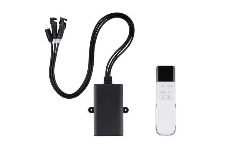
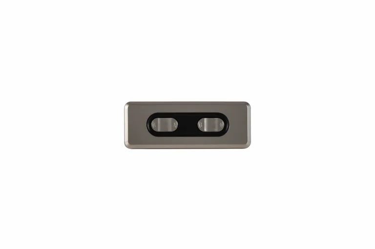
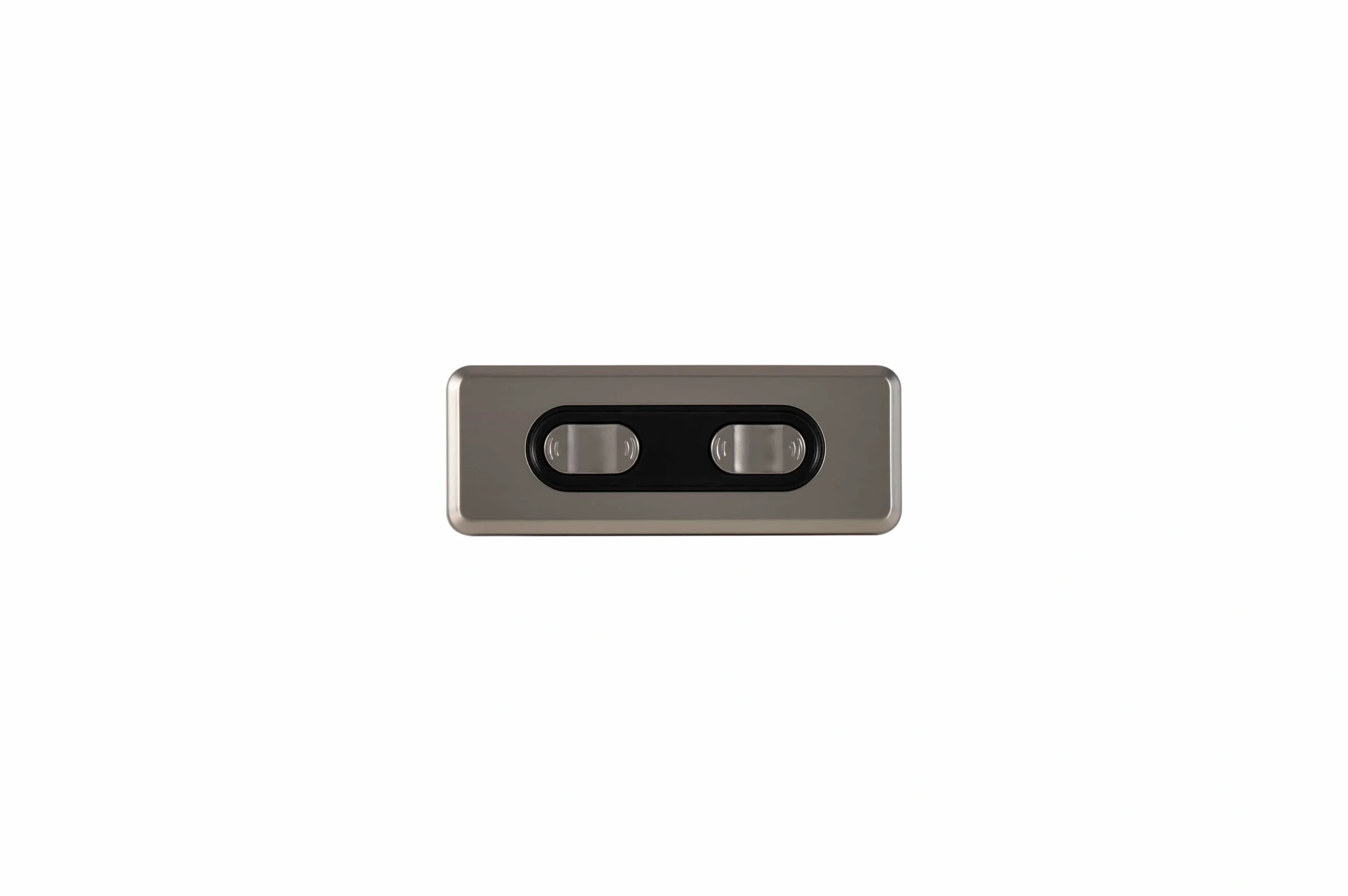
The command source might be a rocker switch, pushbutton, embedded panel, PLC output, wired handset, or remote receiver. The switching stage then routes power to the motor in the required direction.
A control unit connects command inputs, power, and motor outputs through defined interfaces.
In a simple manual circuit, the switch itself may reverse polarity. In a more structured system, a low-current button tells control electronics what to do, while relays or an H-bridge handle motor current.
This separation matters because command signals and motor power are different electrical jobs. A small logic input can request motion without being able to carry the current required by the motor.
How basic direction reversal works
Many brushed-DC linear motion devices use two motor leads. If one polarity makes the rod extend, reversing the polarity makes it retract.
Conceptually:
| Command | Motor lead A | Motor lead B | Result |
|---|---|---|---|
| Extend | +DC | 0 V | Motor turns one direction |
| Retract | 0 V | +DC | Motor turns the opposite direction |
| Stop | no drive / brake state | no drive / brake state | Motion stops |
The exact stop state depends on the circuit. Some designs disconnect the motor and let it coast. Others electrically brake it. That behavior must be defined rather than assumed.
Switch or relay control
A reversing switch or relay arrangement can swap polarity mechanically. This is often enough for simple extend/retract motion where intermediate position does not need to be measured.
H-bridge control
An H-bridge reverses motor current electronically. It can also support pulse-width modulation for speed control, current sensing, braking modes, and fault handling.
An H-bridge adds capability, but it also creates additional design requirements such as switching timing, current rating, thermal limits, and protection.
Basic wiring table
The exact terminal names vary by product, but the engineering roles are consistent.
| Connection group | What it carries | What to verify |
|---|---|---|
| DC supply input | Electrical energy for control and motor load | allowable voltage range, polarity, continuous/peak current, fuse/protection, connector rating |
| Motor output | Bidirectional power to the motor | motor voltage/current, polarity convention, conductor size, connector/pinout |
| Extend/retract inputs | Motion requests | input voltage/logic type, momentary vs maintained behavior, priority/interlock rules |
| Stop/enable input | Permission to run | normally enabled/disabled state, fail-safe behavior, restart rule |
| Limit inputs | End-position or overtravel information when externally available | electrical type, normally open/closed logic, response to activation |
| Feedback inputs | Position/speed information | sensor type, supply, signal scaling, pulse count or analog range, direction convention |
| Status/fault outputs | Ready, moving, limit, or fault state | output type, voltage/current capability, meaning of each state |
| Communication port | Commands, parameters, or diagnostics | physical layer, protocol, address, watchdog, loss-of-communication behavior |
This is a function table , not a universal pinout. Never wire an unfamiliar device from a generic table alone. Use the exact wiring diagram and interface data for the chosen components.
Internal end limits are not the same as feedback
A common beginner mistake is to treat every “limit” as a position sensor available to the control system.
Some actuators contain internal end switches that simply interrupt motor current when the mechanism reaches full extension or retraction. In that architecture, the external control electronics may not receive a separate limit signal at all.
Other systems expose:
- positive and negative limit inputs;
- a home/reference switch;
- Hall-effect pulses;
- potentiometer position;
- encoder signals;
- current or obstruction information.
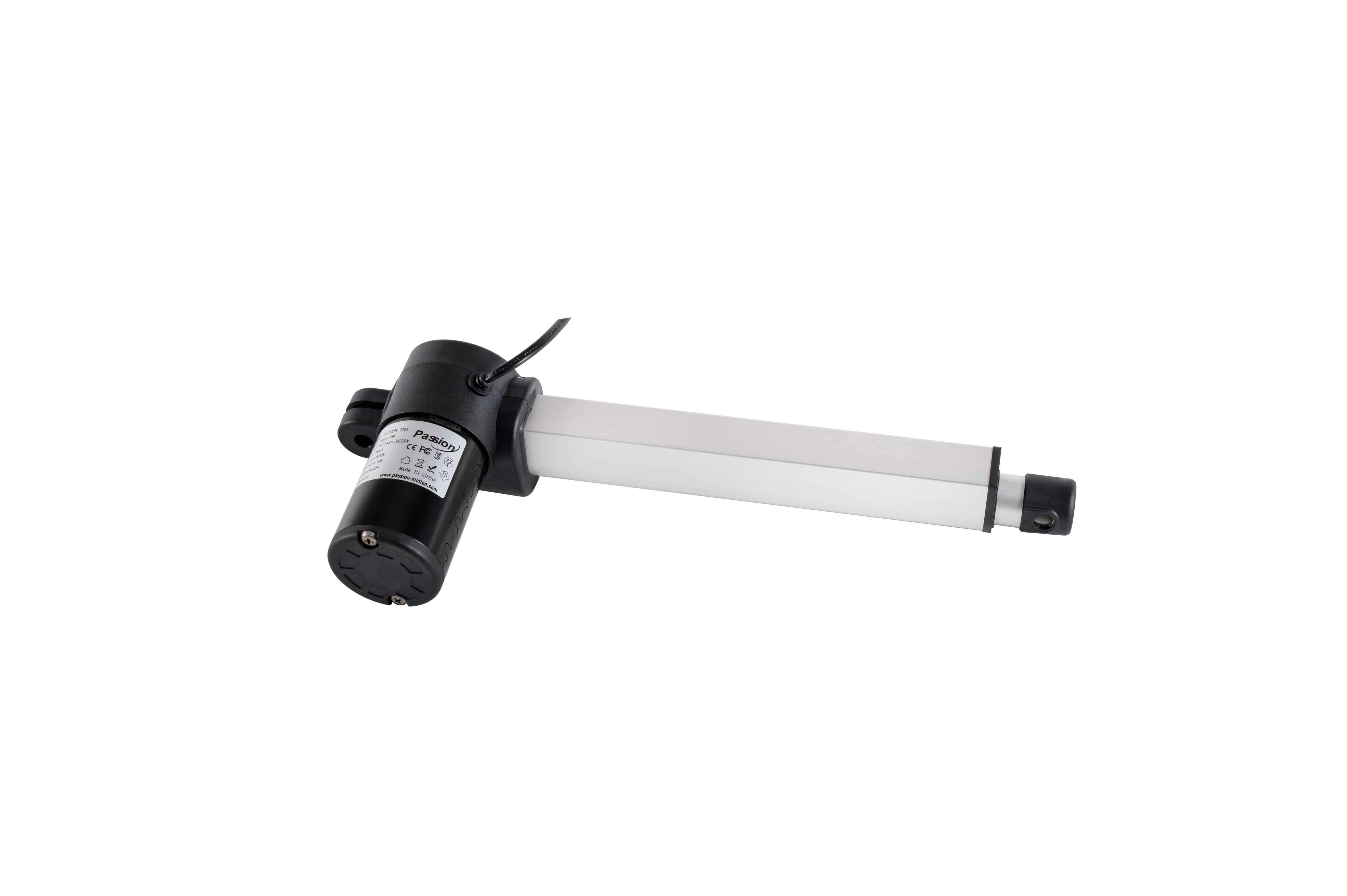
End limits, motor leads, and any feedback interface must be understood before wiring a motion system.
The difference matters because an internal end switch can stop travel without telling the supervisory logic the exact intermediate position.
What feedback adds
Feedback creates an information path from the actuator back to the control electronics.
Depending on the sensor and logic, feedback can support:
- measured position;
- speed calculation;
- intermediate-position commands;
- preset positions;
- position-error detection;
- multi-axis coordination;
- diagnostics;
- more controlled fault recovery.
Progressive Automations and SMC both illustrate that actuator-control capability changes with the available feedback and integrated electronics, while Firgelli and Tolomatic show how end limits and actuator construction fit into the motion chain.
Feedback should therefore be specified as an interface: sensor type, electrical signal, scaling, direction, required supply, and fault behavior .
Power matching: control voltage is only part of the question
A motion circuit can fail even when the nominal voltage looks correct.
The power path should be checked for:
- allowed DC voltage range;
- normal running current;
- startup current;
- peak or stall current;
- number of motors that may run together;
- cable voltage drop;
- connector current rating;
- fuse or current-limit behavior;
- heat dissipation;
- duty cycle.
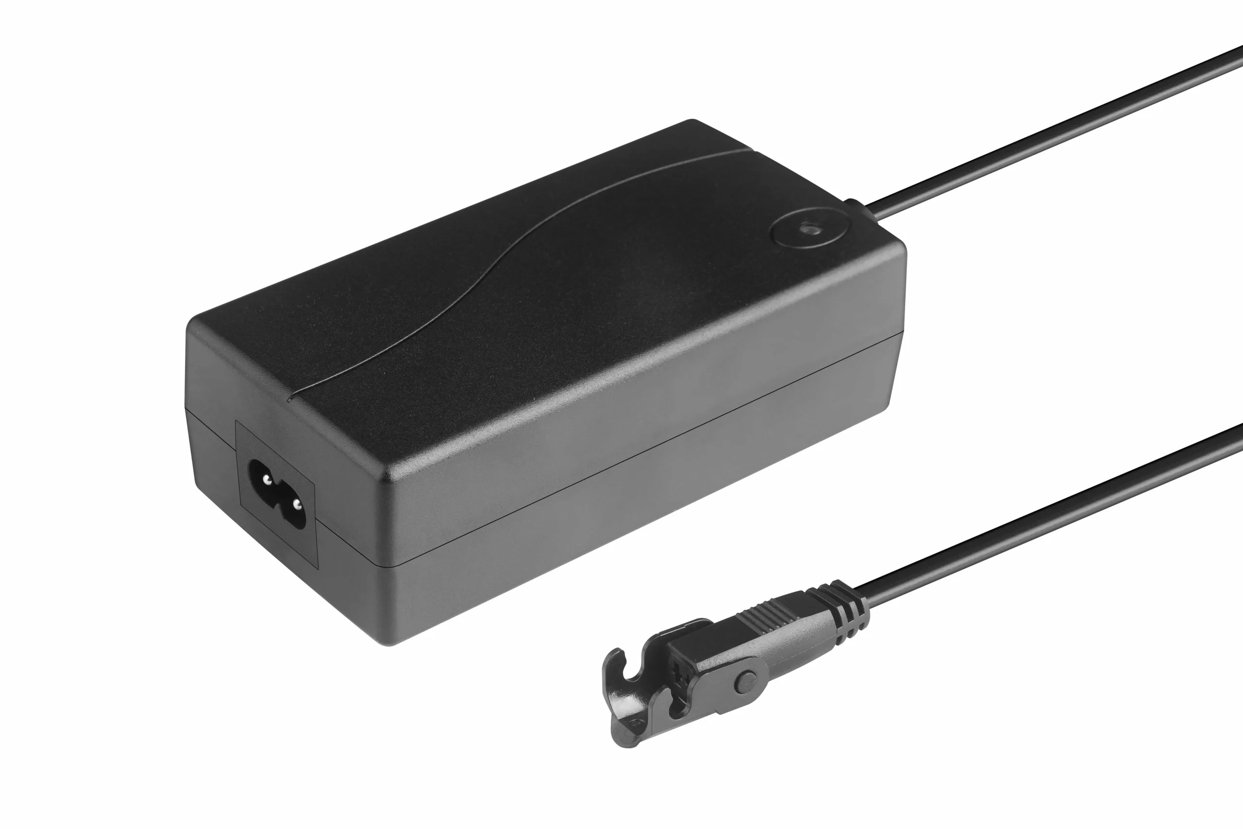
The supply and drive stage must be sized for the actual operating and transient current demand.
A small logic circuit can command a large load only if the switching stage and supply are sized for that load.
For project-level electrical matching, use ServoCylMotion's system compatibility resource rather than assuming that the same nominal voltage means two components can be combined.
Protection should be defined before wiring
Protection is not a single feature. Different architectures may provide different layers.
Typical questions include:
- What happens on a short circuit?
- Is motor current limited?
- How is a stall detected?
- What happens if the mechanism hits an obstruction?
- Is overtemperature detected?
- What happens if supply voltage drops?
- Does a fault latch until reset?
- Can motion restart automatically after power returns?
- Is an external emergency-stop interface required?
Do not assume a product provides a function because another control product does. Verify the specific hardware and system behavior.
For OEM projects that need integrated panel or command-interface options, see embedded control panels . That commercial page owns product selection; this article stays focused on how the electrical roles fit together.
Channel count: one output is not the same as coordinated multi-axis control
A control unit may have one motor output or several. Channel count tells you how many outputs are physically available, but it does not by itself tell you how those channels behave.
Possible modes include:
- one independent motor;
- several independent motors;
- several motors receiving the same command;
- feedback-based coordinated motion.
True synchronization is a separate control problem. Sending the same voltage to two motors does not guarantee equal travel when friction, load, or mechanical efficiency differs.
For systems that require coordinated multi-motor motion, use the multi-motor synchronization capability rather than treating channel count as proof of synchronization.
Command sources can change without changing the motor principle
The same basic motor-power stage can sometimes be driven from different command sources:
- rocker switch;
- embedded keypad;
- PLC;
- wired handset;
- remote receiver.
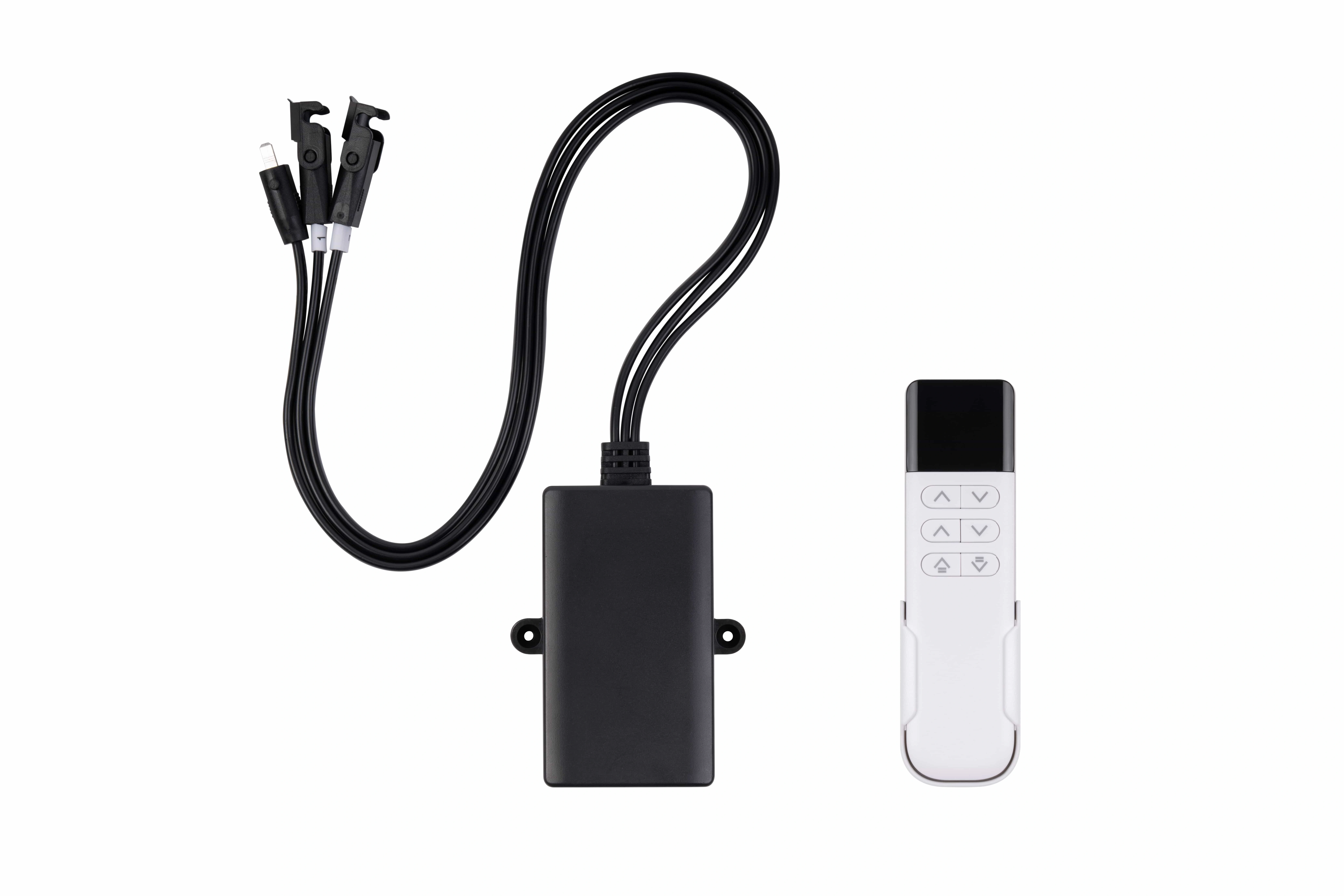
Remote control is one possible command source; the underlying motor-power and protection logic still has to be defined.
The command interface still needs defined voltage levels, logic, priority, and loss-of-command behavior. Wireless control, for example, adds pairing, timeout, and interference questions, but it does not remove the need to size the motor-power path correctly.
Commercial wireless options are listed on the wireless motor controls page .
Six common wiring and selection mistakes
1. Assuming the connector proves compatibility
Two plugs can mate mechanically while carrying different pin assignments or signal types.
2. Checking voltage but not current
The supply or switching device may be unable to handle startup or peak motor demand.
3. Treating internal end limits as external feedback
An internal stop may interrupt motor current without providing position data to the control logic.
4. Ignoring motor polarity
Reversing two motor leads may reverse motion direction, but feedback and limit signals have their own wiring conventions.
5. Adding a longer cable without checking conductor size
Longer wiring can increase voltage drop and affect motor performance or signal quality.
6. Assuming multi-channel means synchronized
Multiple outputs may be independent unless feedback and coordination logic are specifically supported.
Control-basics checklist
Before connecting power, confirm:
- supply voltage range;
- continuous and peak current;
- motor lead identification;
- direction/polarity convention;
- whether limits are internal or externally wired;
- feedback type and signal;
- command-input type;
- channel count and channel behavior;
- fuse/current/thermal protection;
- connector and pinout;
- cable gauge and length;
- fault and restart behavior.
If any of these items are unknown, stop at the interface-definition stage rather than testing by trial and error.
For an OEM design that needs a project-specific control architecture, ServoCylMotion control-system OEM support can take the requirements beyond this introductory wiring framework.
FAQs
What does electric actuator control electronics actually do?
It receives a motion request, controls the motor-power path, determines direction, applies stop and protection logic, and may process feedback or status signals.
How is direction reversed on a basic two-wire DC actuator?
A common method is to reverse the polarity applied to the two motor leads. This can be done with an appropriate reversing switch, relay arrangement, or H-bridge. The exact wiring must follow the selected hardware.
Do internal limit switches always need separate wires to the control unit?
No. In some designs, internal limits interrupt motor current directly and do not provide an external signal. Other designs expose limit or position signals. Verify the actuator wiring diagram.
What is the difference between a limit switch and position feedback?
A limit switch usually indicates an endpoint or protection condition. Position feedback provides information about where the actuator is during travel, depending on the sensor type.
Is matching voltage and connector shape enough?
No. Also verify current capacity, pinout, polarity, feedback, signal type, channel behavior, protection, and any communication requirements.
When do I need feedback?
Feedback becomes important when the system must know or correct actual motion—for example intermediate positioning, speed measurement, presets, diagnostics, or coordinated motion.
References
- Progressive Automations — Guide to Control Systems for Electric Linear Actuators
- Actuonix — Options for Controlling Linear Actuators
- SMC — Electric Actuators with Integrated Controllers
- Firgelli — Linear Actuators 101
- Tolomatic — Electric Linear Actuators Explained
- Matara — How to Control a Linear Actuator