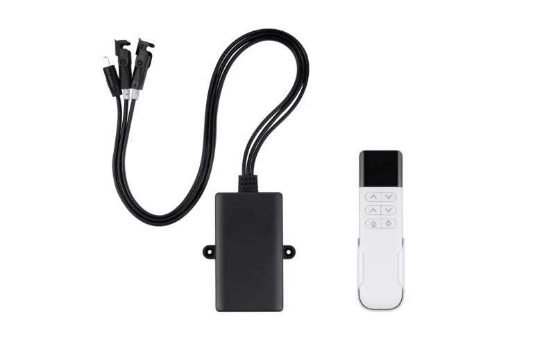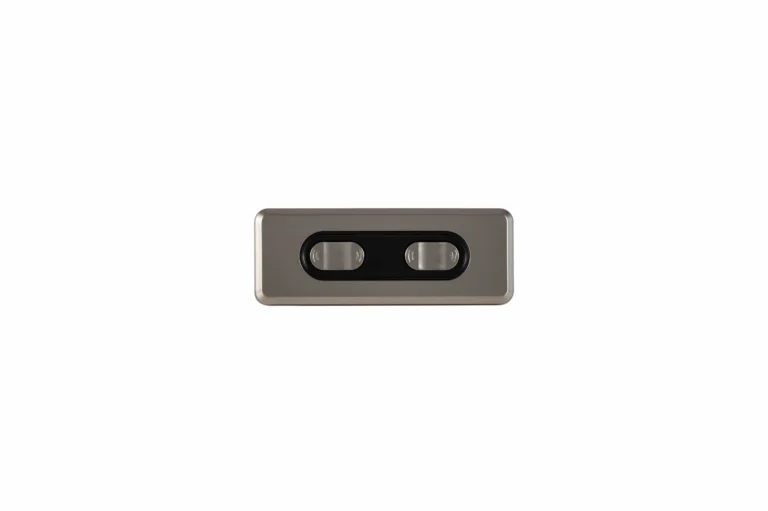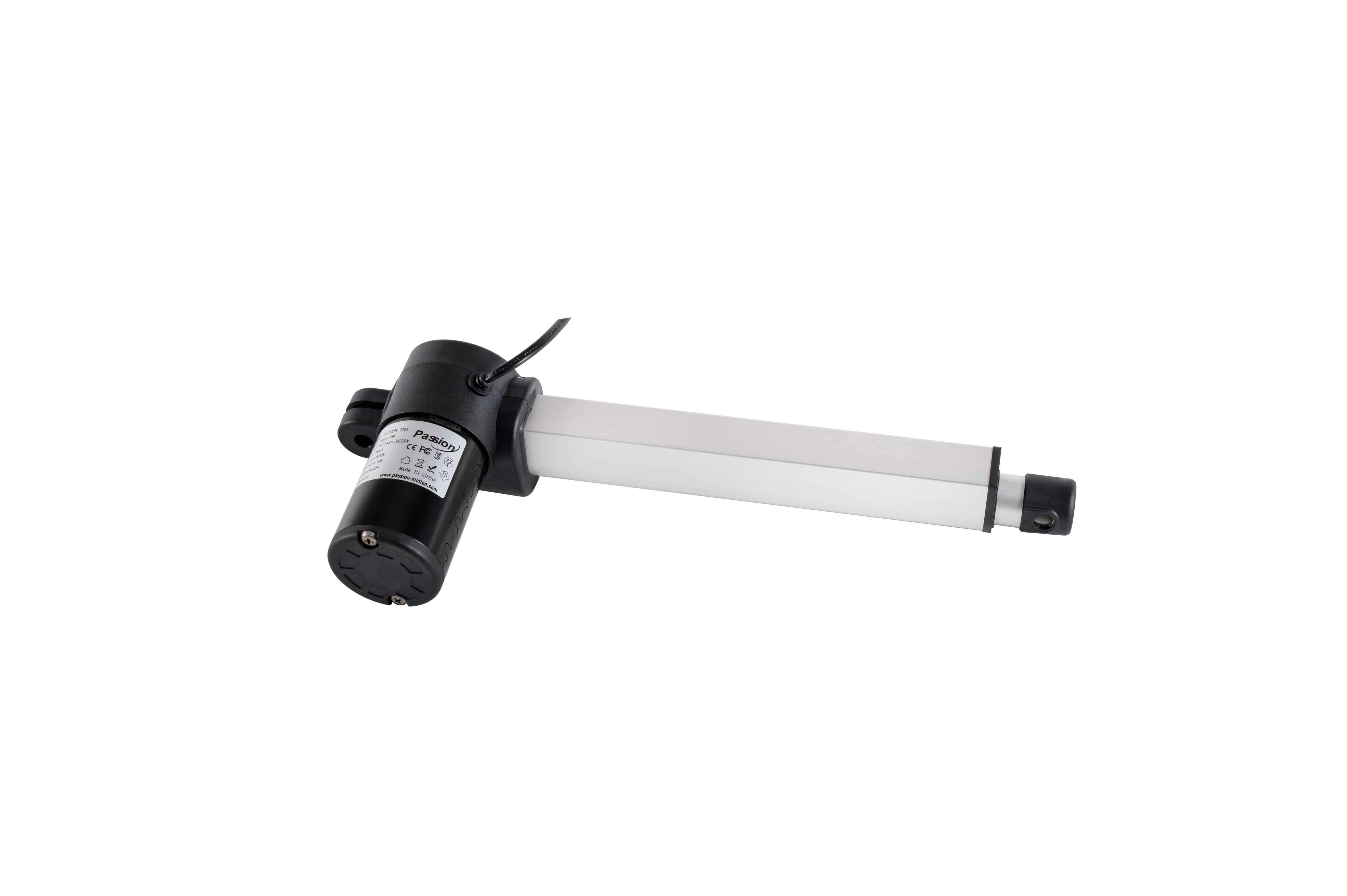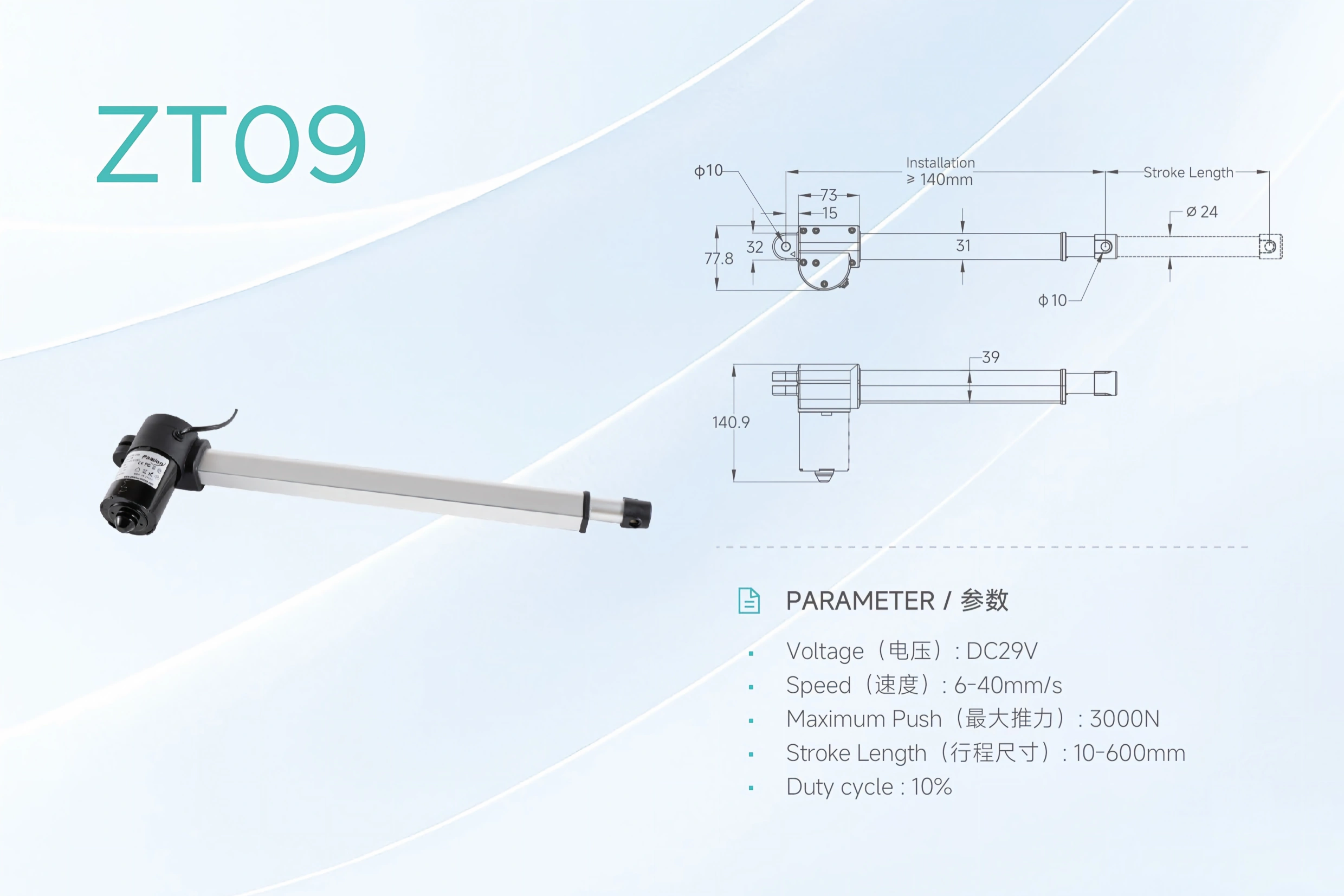
Linear Actuators for Adjustable Beds: OEM Selection Guide
Select linear actuators for adjustable beds by motion zone, load, stroke, closed length, speed, noise, duty cycle, motor count, controls, feedback, power, and validation.

Selecting linear actuators for adjustable beds is a system-design task. The right choice depends on how many bed sections move, how each linkage converts actuator travel into section angle, how much load each zone carries, how quiet the movement must be, and how the control system coordinates multiple motors.
For OEM projects, the most reliable sequence is to define the motion zones first and select components second.
A typical comfort-bed frame may include:
- head/back elevation;
- knee or thigh elevation;
- an optional foot zone;
- an optional neck or lumbar zone;
- whole-frame tilt or height adjustment in more complex designs;
- split left/right zones.
Each zone should have its own load case, stroke, speed, duty cycle, holding requirement, mounting geometry, control channel, and validation plan.
Table of Contents
Motion-zone selection table
| Requirement | Head / back zone | Knee / leg zone | Additional zone | Whole-frame / paired motion |
|---|---|---|---|---|
| Main load input | upper-body and frame load through linkage | lower-body and frame load | zone-specific load | full frame, distributed load, guide friction |
| Force driver | linkage angle and moving mass | leverage and knee geometry | depends on zone | total load, imbalance, guide friction |
| Stroke | derived from required section angle | derived from leg-section motion | often shorter but application-specific | derived from lift or tilt geometry |
| Closed length | must fit inside frame | constrained by crossbars and upholstery | often space-sensitive | constrained by base structure |
| Speed | smooth and comfortable | coordinated with user expectation | zone-specific | may need matched motion |
| Noise | low-noise operation usually important | low-noise operation usually important | important in occupied spaces | frame resonance can amplify noise |
| Duty cycle | intermittent repeated moves | intermittent repeated moves | depends on function | may create higher simultaneous thermal load |
| Holding | must hold selected angle as required | must hold selected angle as required | zone-specific | important for lift/tilt architectures |
| Controls | dedicated buttons/presets may be needed | dedicated buttons/presets may be needed | extra channel/function | coordinated logic often required |
| Feedback | useful for presets/position memory | useful for presets/position memory | depends on function | important when two axes must remain aligned |
| Power | zone current plus control electronics | zone current plus control electronics | adds to system budget | size for worst simultaneous motion |
| Validation | load, cycle, noise, stop, wiring | load, cycle, noise, stop, wiring | zone-specific | load balance, synchronization, fault response |
Each motion zone should be specified by load path, travel, packaging, speed, duty, and control requirements before component selection.
The table is a requirements map, not a product recommendation. It helps the engineering team define what each zone needs before a model is chosen.
Step 1: Define every motion zone and linkage
The actuator does not move the user directly. It pushes or pulls a linkage connected to a hinged bed section.
That means required actuator force changes with:
- pivot position;
- actuator mounting points;
- linkage angle;
- center of gravity;
- user-load distribution;
- mattress and frame weight;
- friction;
- acceleration;
- frame deflection.
The worst force can occur at the least favorable linkage angle rather than at the maximum section angle.
A useful CAD model should include:
- all hinge axes;
- actuator mounting centers;
- moving section mass;
- expected load distribution;
- minimum and maximum section positions;
- frame interference;
- cable routing;
- hard stops.
Do not select from a single “load weight” number without considering geometry.
Step 2: Calculate force across the whole motion
Force should be checked at multiple positions through the stroke.
For each zone, document:
- maximum dynamic force;
- push and pull direction;
- friction allowance;
- design margin;
- expected asymmetric load;
- start/stop transients;
- mechanical efficiency.
If the linkage becomes mechanically unfavorable near one end, the peak force may rise sharply.
Use the actuator sizing resource after the kinematic geometry is known. The calculator should support the engineering process, not replace the load-path analysis.
Avoid using stall force as the normal operating target
A high stall or static number is not the same as a recommended continuous operating point.
The design should leave enough margin for:
- manufacturing tolerance;
- aging and wear;
- friction variation;
- mattress or accessory variation;
- voltage drop;
- temperature.
The final margin should be documented as part of the project requirements.
Step 3: Match stroke and closed geometry together
Stroke is only one dimension.
The frame must also accommodate:
- retracted hole-to-hole length;
- housing width;
- motor/gearbox envelope;
- clevis angle;
- bracket thickness;
- connector position;
- cable exit;
- service clearance.
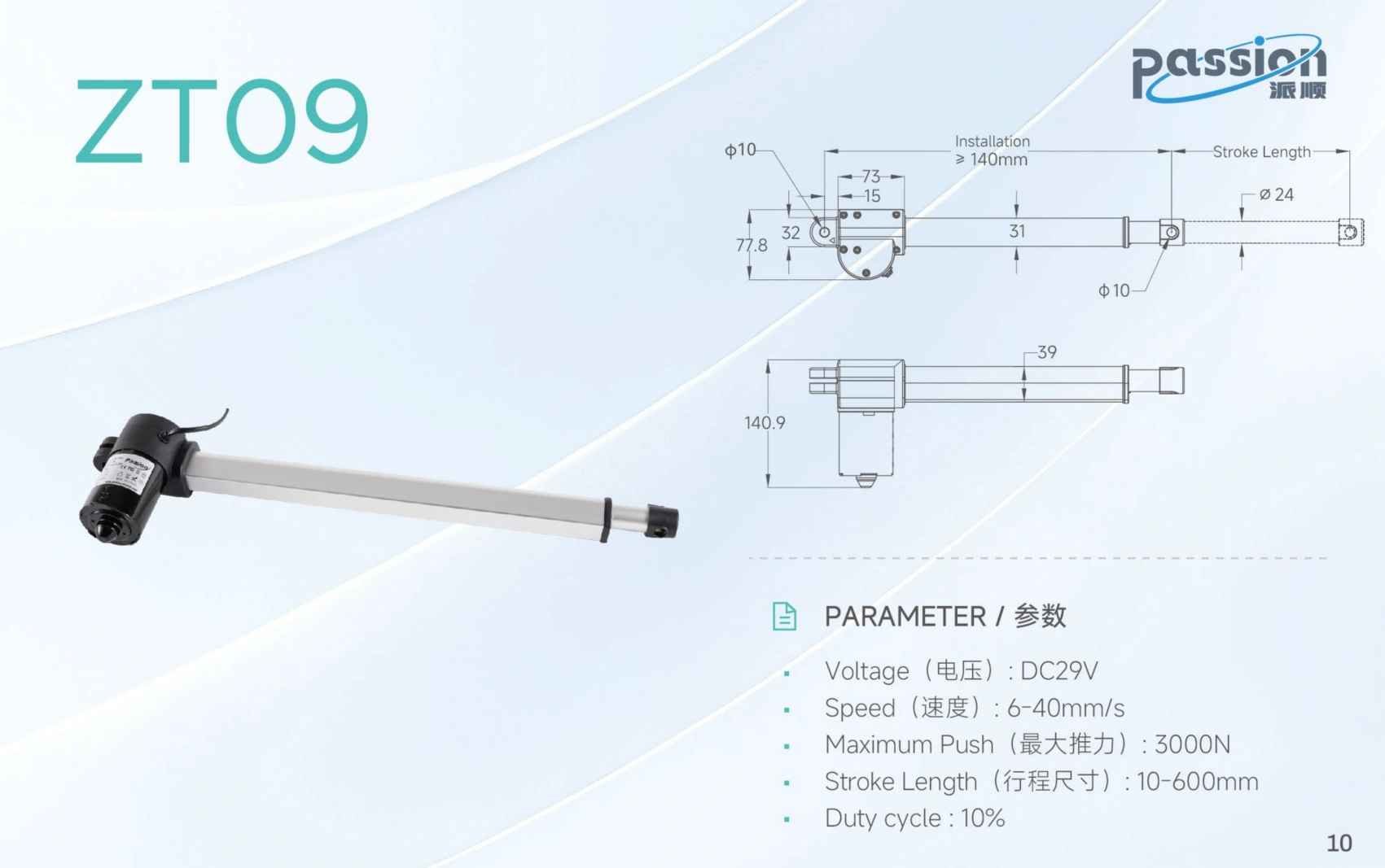
Similar travel can require very different closed length, mounting centers, and connector clearance.
Two drives with similar travel can have very different installation envelopes.
For compact furniture, closed length can decide feasibility before force does.
Check full travel in CAD
At both end positions, verify:
- no housing interference;
- no bracket collision;
- no cable pinch;
- no over-angle at clevis joints;
- no side loading caused by frame deflection;
- no binding at tolerance extremes.
The actuator should remain primarily axially loaded. Hinges and frame structure should carry lateral forces and moments.
Step 4: Choose single-drive, dual-drive, or multi-zone architecture
There are several common system approaches.
One drive per zone
A single drive is the simplest architecture when the frame section is stiff, well guided, and loaded reasonably close to the design centerline.
Advantages:
- fewer parts;
- simpler wiring;
- simpler control;
- no synchronization between parallel axes.
Risks:
- frame twist if the structure is wide or flexible;
- larger force concentration at one mounting location.
Integrated dual-drive architecture
A compact dual-drive unit can combine two independent bed-zone motions in one package.
This can reduce:
- wiring;
- control-box complexity;
- assembly count.
But the OEM still needs to define:
- which zones each output controls;
- force and travel for each output;
- control behavior;
- replacement strategy;
- cable routing;
- accessory connections.
Separate multi-zone drives
Additional zones usually require separate outputs.
If more than one axis supports the same moving structure, define:
- channel mapping;
- feedback on each axis;
- allowed position mismatch;
- stop behavior when one axis faults;
- reset/homing behavior;
- load sharing.
Applying the same command to two motors is not proof that they remain aligned. For paired-axis projects, review multi-motor synchronization as a separate engineering requirement.
Step 5: Treat low noise as a system requirement
A drive can sound quiet on a bench and become louder after installation.
Noise is affected by:
- gearbox;
- motor speed;
- screw transmission;
- bracket stiffness;
- frame resonance;
- loose fasteners;
- mattress support;
- cable contact;
- load imbalance.
Define:
- measurement distance;
- representative load;
- room conditions;
- motion direction;
- speed;
- assembled-frame configuration.
The target should be validated in the production-intent frame.
Step 6: Specify duty cycle and thermal behavior
Comfort furniture normally moves intermittently, but the OEM should still define the actual use case.
Record:
- run time per adjustment;
- number of adjustments per hour;
- expected daily cycles;
- simultaneous zone combinations;
- ambient temperature;
- enclosure ventilation;
- rest time.
The motor, control electronics, connectors, and power source all contribute to the thermal system.
A prototype that performs a few successful cycles is not enough evidence for lifecycle suitability.
Step 7: Define holding and power-off behavior
Each bed zone needs a clear requirement for what happens when power is removed.
Possible design expectations include:
- hold the selected position;
- resist backdriving under the intended load;
- allow controlled service movement;
- remain mechanically stable after a fault.
Do not assume a transmission is self-locking without evidence.
The project should verify:
- unpowered holding;
- creep;
- backdrive threshold;
- brake behavior if used;
- recovery after power returns.
Step 8: Freeze controls, handset functions, and presets
The control interface is part of actuator selection.
Possible requirements include:
- one button pair per zone;
- simultaneous multi-zone command;
- memory presets;
- lockout;
- wired handset;
- wireless handset;
- local service control;
- status feedback;
- reset behavior.
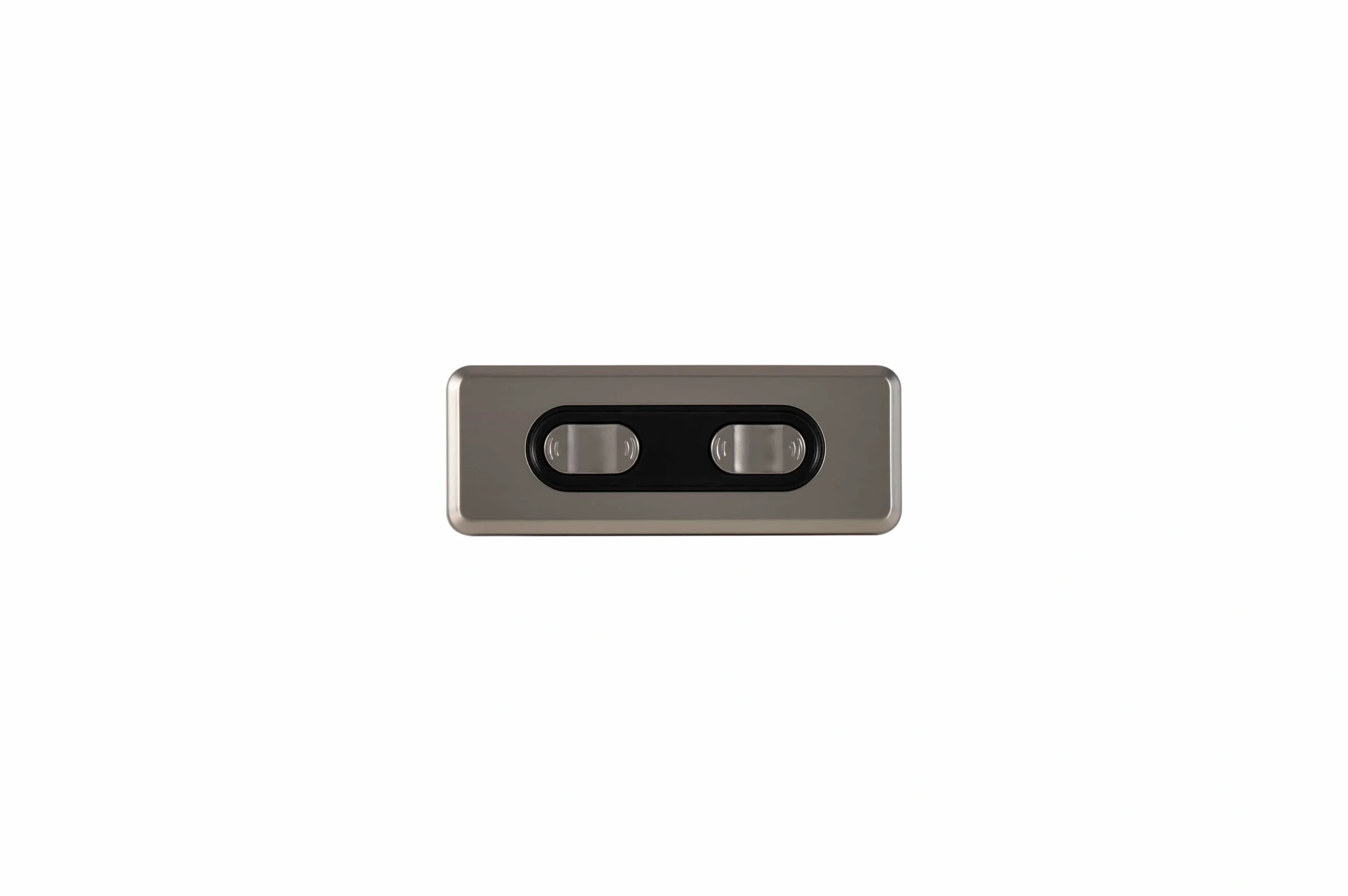
Motion zones, channel count, presets, feedback, synchronization, and fault behavior should be frozen as one control requirement.
These features determine how many channels the control electronics require and whether position feedback is necessary.
For example, repeatable presets usually require more than timed motor operation. The system must know or recreate position in a defined way.
Step 9: Decide when feedback and synchronization are required
Feedback can support:
- position memory;
- repeatable stopping;
- synchronized paired motion;
- drift detection;
- diagnostics;
- recovery after faults.
Possible sensor types include Hall-effect pulses, potentiometers, and encoders.
The important requirement is not the sensor name alone. Define:
- electrical interface;
- scaling;
- direction convention;
- reference behavior;
- what happens after power loss;
- allowed synchronization error;
- response to missing feedback.
Step 10: Size power for simultaneous motion
The power system should be sized for the worst allowed combination of zones.
Include:
- startup current;
- normal running current;
- peak/stall condition;
- controller electronics;
- simultaneous motor count;
- cable voltage drop;
- connector current rating;
- fuse/current-limit strategy.
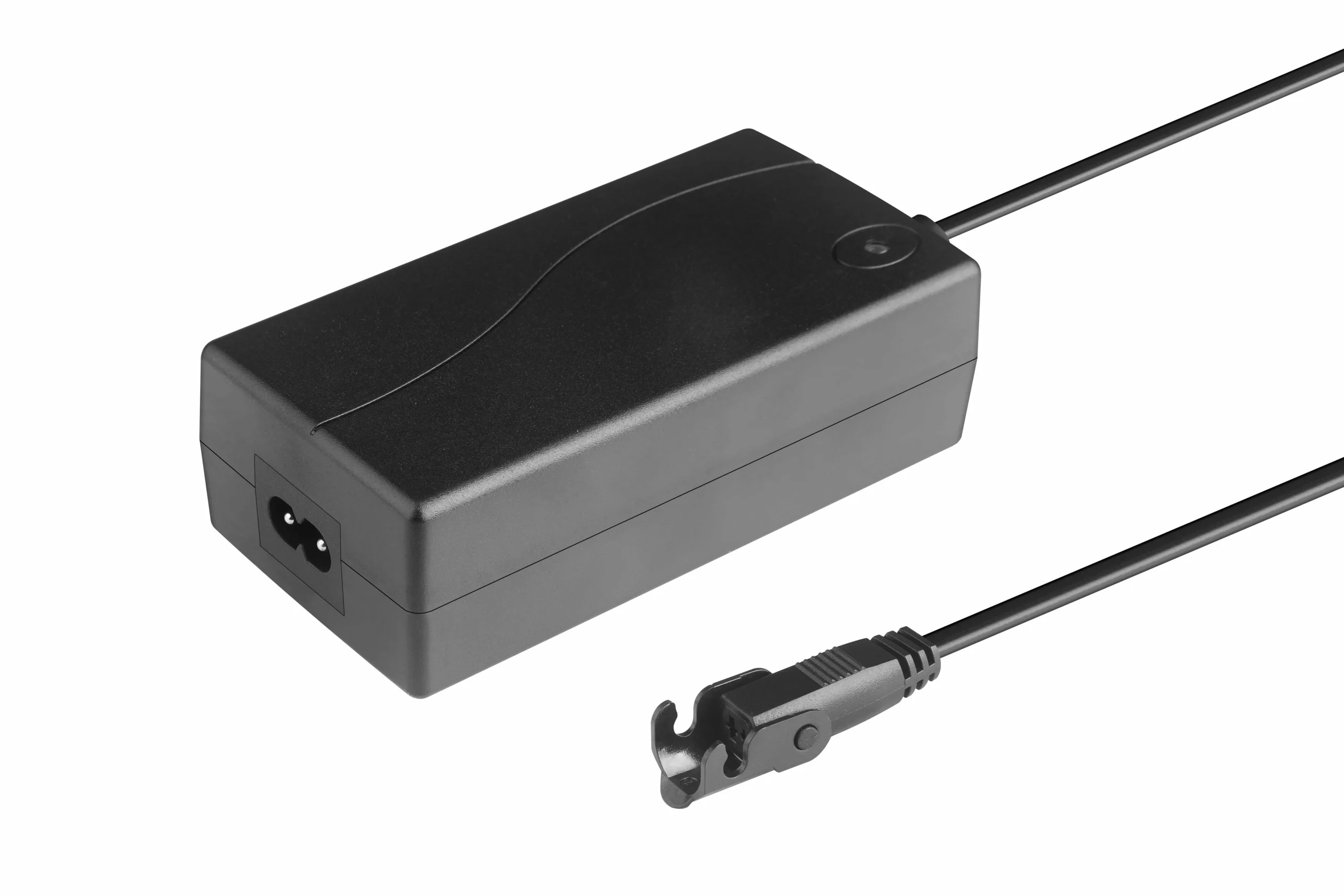
The power system must be sized for the worst permitted simultaneous-motion condition, not for one motor in isolation.
A supply sized for one motor may be insufficient if two or more zones are allowed to move together.
For a project with known motion components, controls, and supply candidates, use the system compatibility resource to verify them as one configuration.
Step 11: Design the harness for an articulated frame
Bed frames move around hinges and crossbars, so cable design is part of mechanical design.
Check:
- bend radius;
- strain relief;
- abrasion;
- connector retention;
- upholstery staples or sharp edges;
- moving hinge zones;
- service loops;
- cable length at both travel extremes.
A cable should never become the mechanical travel stop.
Harness validation should use the complete articulation cycle, not a static routing review.
Step 12: Review pinch, obstruction, and fault behavior
Moving sections can create trapping zones around:
- hinges;
- brackets;
- clevises;
- crossbars;
- frame edges;
- cable loops.
The machine-level design should define:
- guarded geometry;
- hard stops;
- command-release behavior;
- current/force monitoring where applicable;
- obstruction response;
- recovery after a fault.
Do not treat upholstery as a safety device.
OEM validation checklist
Before production release, validate the complete bed-motion system.
Mechanical
- full-stroke interference check;
- force at worst linkage positions;
- bracket and frame stiffness;
- side-load control;
- asymmetric-load behavior;
- mounting fastener retention.
Motion quality
- loaded speed;
- acceleration/deceleration;
- noise;
- repeatability;
- stop behavior;
- unpowered holding.
Controls
- every zone independently;
- every allowed simultaneous zone combination;
- presets if used;
- feedback calibration;
- synchronization if used;
- fault/reset behavior;
- stuck-command behavior.
Electrical
- startup current;
- running current;
- worst simultaneous current;
- supply voltage at the farthest motor;
- connector heating;
- fuse/current-limit behavior.
Harness
- bend-cycle test;
- pinch/abrasion check;
- connector retention;
- full articulation routing.
Thermal and lifecycle
- duty-cycle test at representative load;
- worst ambient condition;
- repeated cycle test;
- post-cycle noise;
- backlash;
- holding;
- cable condition.
The exact hardware, firmware, harness, and parameter revision used in validation should be recorded.
How to move from requirements to a commercial solution
Once the engineering sheet is complete, the project can move to the adjustable-bed industry solution without mixing commercial ownership into this selection article.
If a project already has a frame drawing, load cases, stroke targets, motor-zone map, and control requirements, send them through ServoCylMotion contact for project-specific review.
FAQs
Should each bed motion zone be sized separately?
Yes. Head, leg, tilt, height, and other zones can have different loads, leverage, stroke, speed, and duty requirements.
When is an integrated dual-drive architecture useful?
It can be useful when two common motion zones can be packaged compactly and controlled as part of one coordinated system. The OEM still needs to verify each output's load, travel, control behavior, and replacement strategy.
When is position feedback needed?
Feedback becomes important when the system needs presets, synchronization, repeatable positioning, drift detection, or diagnostic information.
Why is low noise not just a motor specification?
Because the complete frame can amplify vibration. Brackets, upholstery support, fasteners, and structural resonance influence the final acoustic result.
How should power be sized for several motion zones?
Use the worst permitted simultaneous-motion case, including startup and transient current, cable voltage drop, and the controller's total current limit.
What should be validated before production?
Validate full-load motion, geometry, noise, duty/thermal behavior, holding, wiring, controls, feedback, synchronization where used, fault response, and lifecycle in a production-intent frame.