Dual Motor Desk Frame Synchronization: Control, Drift & Validation
Learn how dual-motor desk frame synchronization works, why lifting sides drift, how reset and recovery differ by system, and what OEM teams should validate.

Dual motor desk frame synchronization is the engineering task of keeping two independently driven lifting sides coordinated closely enough that one shared worksurface remains level and mechanically well behaved throughout travel. The controller is essential, but synchronization is not a controller-only feature. Motor and transmission matching, lifting-column alignment, load distribution, wiring, power, feedback or other monitored state, fault handling, and the reference/reset process all affect the result.
For an OEM project, the useful question is not simply whether a frame has two motors. The useful question is: what does the system measure or infer, how does it respond to mismatch, what happens when one side cannot follow, and how will the assembled desk be tested before release?
Table of Contents
Key Takeaways
- Two motors create two driven motion paths that must support one common worksurface without unacceptable side-to-side mismatch.
- Synchronization performance depends on both mechanical consistency and control behavior.
- Uneven load, friction, misalignment, cable or connector issues, interrupted motion, a lost reference, or a stalled side can all contribute to drift.
- Different systems use different feedback and correction architectures. Do not assume one sensor type or one control algorithm applies to every desk.
- Reset or re-homing generally restores a known reference; the exact procedure must come from the selected control configuration.
- An OEM specification should define a project-specific mismatch criterion and validate it under representative and asymmetric loading.
What Must Stay Synchronized in a Two-Motor Desk Frame?
In a typical two-leg dual-motor architecture, each lifting side has its own drive path. Both sides support the same desktop or upper frame, so their movement cannot be treated as two unrelated axes.
The system has to control several relationships at once:
- Position relationship: one side should not rise or lower far enough ahead of the other to tilt the worksurface beyond the project limit.
- Speed relationship: a small speed difference can accumulate into position error over a long move.
- Start and stop behavior: one side should not begin, decelerate, or stop in a way that creates an unacceptable transient twist.
- Fault behavior: if one side stalls, loses power, becomes obstructed, or loses usable feedback, continued motion on the other side can increase misalignment.
- Reference state: after installation, a fault, or an interruption, the controller needs a valid basis for interpreting both sides as aligned.
That is why desk motor synchronization should be defined as behavior that can be measured, not as a label on a control box.
Mechanical Consistency Comes Before Electronic Correction
A controller can correct a limited mismatch, but it should not be expected to compensate for a badly assembled frame.
Before tuning or approving synchronization behavior, review the mechanical system for:
- lifting columns installed square to the intended structure;
- consistent mounting height and bracket position;
- excessive friction or binding on one side;
- unequal fastener preload or structural distortion;
- differences in motor, gear, or transmission behavior;
- cable drag that changes through the stroke;
- a desktop or cross-member that twists under asymmetric loading;
- floor or foot-level conditions that preload one side of the frame.
Two nominally identical motors can still behave differently because of production variation, gear friction, load, temperature, and installation conditions. Good mechanical matching reduces the amount of active correction the control system has to perform.
How a Dual-Motor Synchronization Controller Works at Principle Level
A synchronized system needs more than two output channels or a shared up/down command. At a high level, the control sequence is:
- issue a common motion command;
- observe or infer the state of each driven side;
- compare the sides or compare each side against the intended motion;
- calculate whether the mismatch remains acceptable;
- correct one or both motor commands when the design permits;
- stop or enter a fault state when the mismatch or another fault condition exceeds the permitted logic.
The exact signal used for that process varies by design. Industry implementations can use position or rotation feedback, motor-current information, or other monitored signals. Some architectures compare both sides directly; others coordinate each side against a reference or master command.
The important OEM requirement is therefore not “use sensor X.” It is to define what the system must accomplish under the real desk geometry and load cases, then verify the selected controller and motion components together.
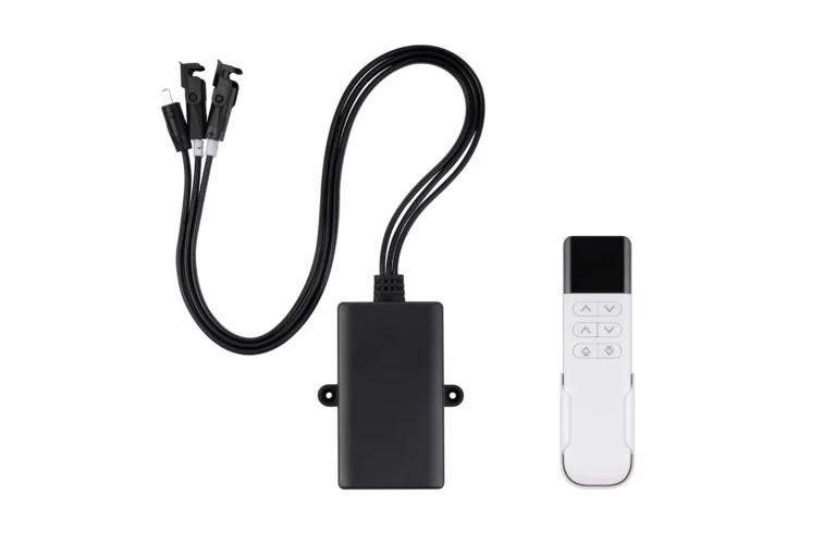
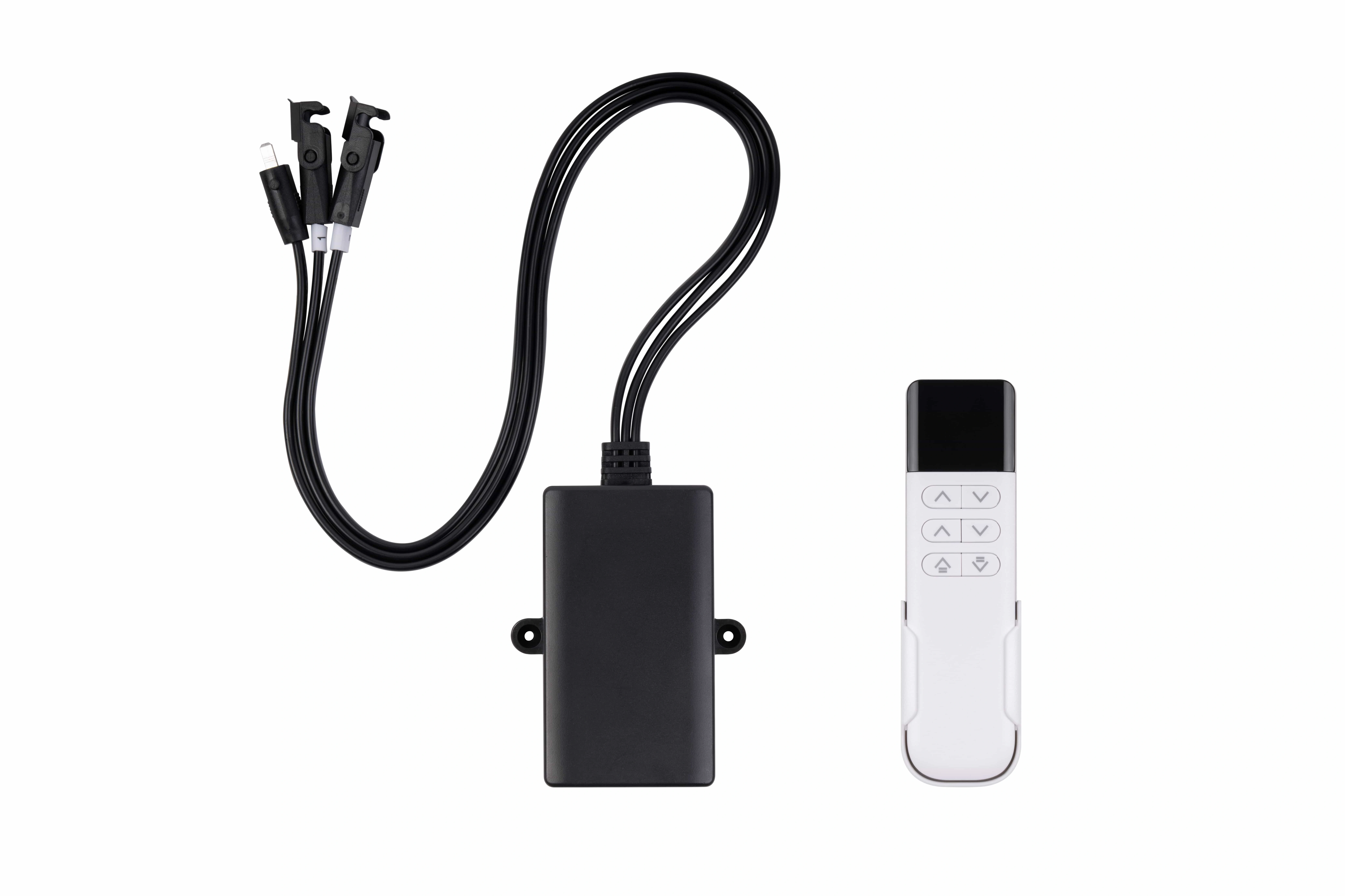
YK-06 is the documented two-channel synchronized option in the current ServoCylMotion YK controller family.
Why Dual-Motor Desk Frames Drift Out of Sync
Side-to-side mismatch normally comes from one or more of four categories.
1. Uneven Load or Changing Resistance
A heavy monitor arm, PC, storage module, cable bundle, or other equipment concentrated toward one side changes the effort required from that lifting path. If one side sees more resistance, it can lag unless the control system detects and manages the difference.
The same effect can appear when friction changes through travel or one column begins to bind.
2. Mechanical Alignment or Structural Problems
A frame can be electrically healthy and still synchronize poorly if the structure introduces unequal resistance. Common engineering checks include column parallelism, mounting geometry, cross-member alignment, desktop stiffness, foot leveling, and whether the moving structure is forcing one lifting side laterally.
If the frame racks under load, the resulting mechanical resistance can become a control problem.
3. Electrical, Cable, or Connector Issues
The two motor paths depend on a complete electrical chain. A loose connector, damaged cable, incorrect routing, unstable connection, or an unsuitable power arrangement can affect one side differently from the other.
Voltage is only one compatibility field. A complete review also considers simultaneous current demand, startup behavior, connectors, polarity, motor interfaces, cable lengths, and the selected controller configuration.
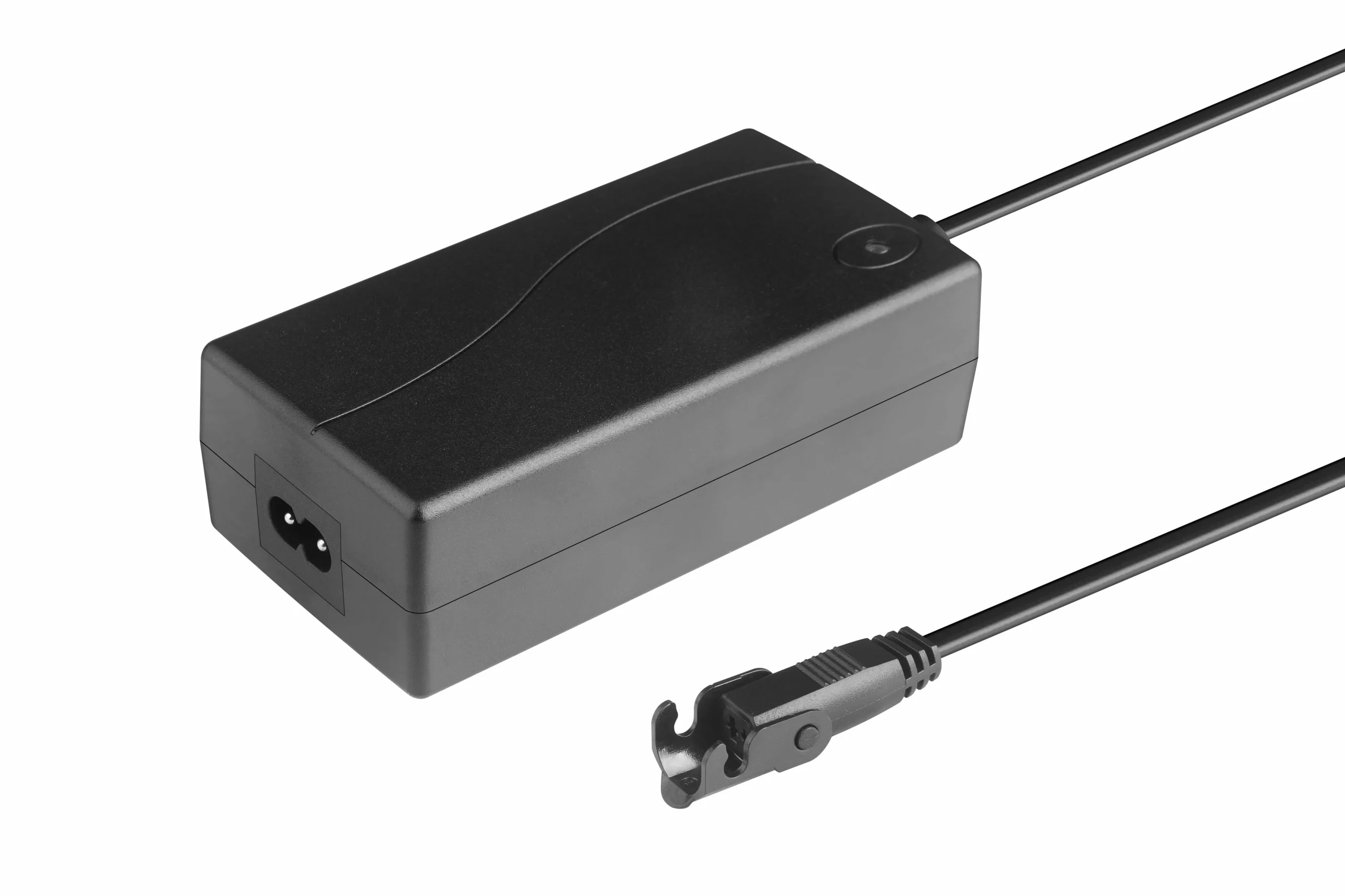
Power source, connectors, and cable routing should be reviewed together with the motor and controller configuration.
4. Lost Reference, Feedback Fault, Stall, or Interrupted Motion
Depending on the control design, synchronization can also be affected when:
- one side stalls or encounters an obstruction;
- one channel is disconnected;
- usable feedback is interrupted or becomes invalid;
- motion is stopped during an abnormal condition;
- power is interrupted before the controller completes its expected sequence;
- the controller no longer has a valid common reference.
The correct recovery action depends on the system design. Continuing to command movement without understanding why one side is lagging can increase the mismatch.
A Practical Troubleshooting Matrix
For engineering or service review, classify the symptom before replacing components or changing control settings.
| Symptom | Possible category | First engineering checks | Escalate when |
|---|---|---|---|
| One side gradually leads through a long move | Load, friction, speed mismatch, feedback/correction | Compare load distribution, mechanical resistance, connectors, and behavior in both directions | Mismatch repeats after mechanical and electrical checks |
| Desk starts level but becomes tilted near one end of travel | Alignment, binding, reference, end-of-travel behavior | Check column geometry, interference, cable drag, and reference procedure | One side repeatedly reaches a limit or fault first |
| One motor stops while the other attempts to continue | Power path, connector, stall, fault logic | Stop motion; inspect connectors, obstruction, load, and system fault indication | The cause is not obvious or the system cannot recover safely |
| Mismatch appears after power loss or service work | Reference/calibration state | Follow the documented initialization or re-homing procedure | Re-reference does not restore coordinated motion |
| Synchronization changes only with a heavy one-sided load | Asymmetric loading, structure, control margin | Reproduce with a defined load and inspect structural deflection or binding | Project acceptance criteria are exceeded |
| Intermittent mismatch changes when cables move | Cable/connector path | Inspect routing, strain relief, connector retention, and moving loops | A damaged or unstable electrical path is suspected |
This table is a diagnostic framework, not a universal service procedure. The exact fault codes, safe test limits, and reset actions belong to the selected control system.
Reset and Re-Homing: What They Actually Accomplish
A reset or re-homing process is often misunderstood as “fixing the motors.” Its more important role is to restore a known relationship between the controller's internal state and the actual mechanical positions of the lifting sides.
Depending on the design, a re-reference sequence may:
- move the system toward a known mechanical or control reference;
- clear an error state after a permitted fault;
- re-establish the relative position relationship between channels;
- confirm that both sides can reach the expected reference condition;
- prepare the controller to resume normal coordinated movement.
There is no universal button sequence that is correct for every dual-motor desk. Holding a key for a certain number of seconds, driving to a lower limit, or performing another sequence is configuration-specific. OEM documentation should therefore include the exact initialization, reset, and recovery procedure for the released hardware and firmware combination.
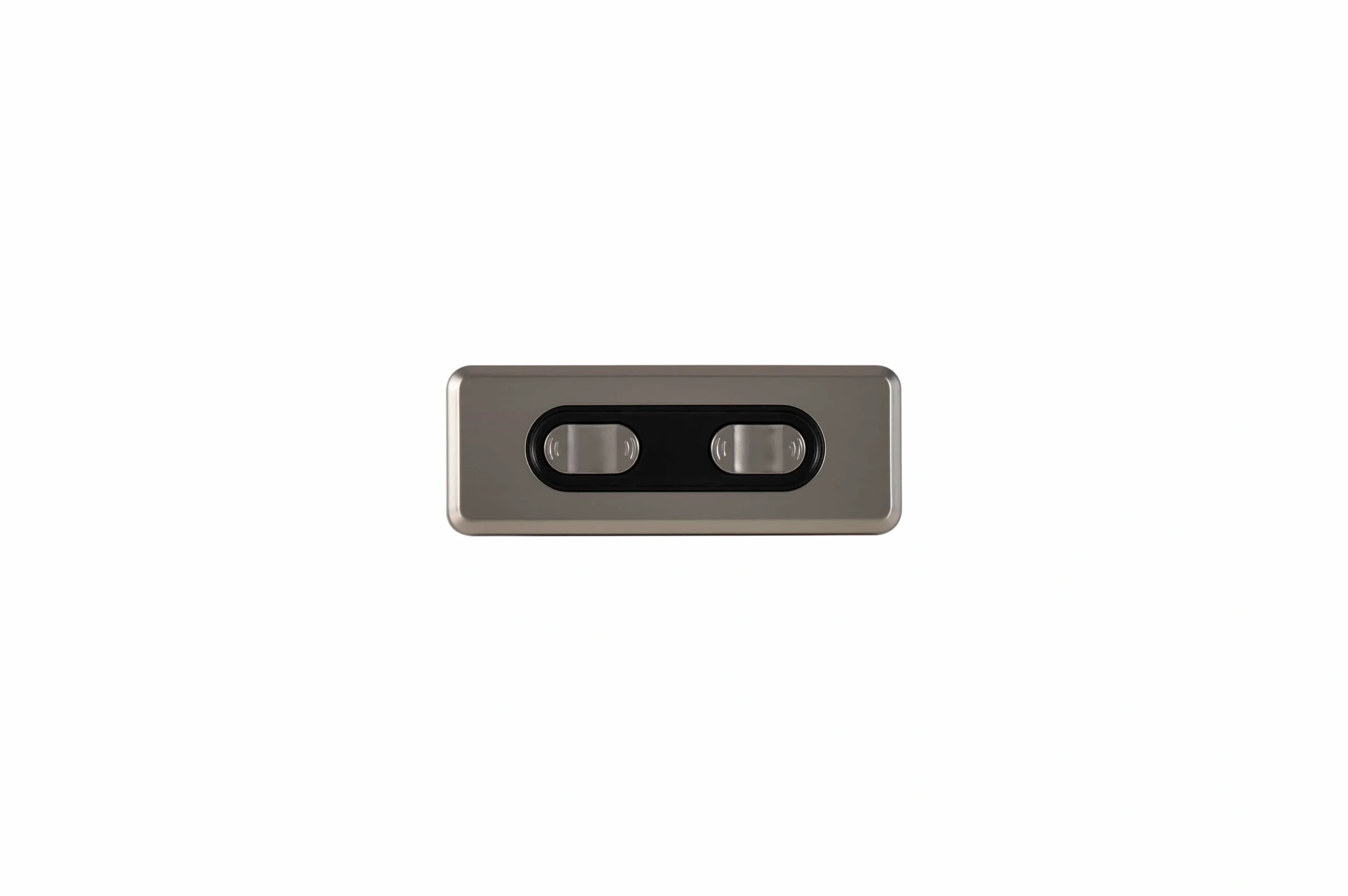
Operator-interface behavior and any reset or homing sequence should be confirmed for the selected control configuration.
Define Synchronization as an OEM Acceptance Requirement
The strongest specification does not say only “synchronized control.” It defines what acceptable behavior means for the actual desk.
A practical requirement set should answer:
- What side-to-side mismatch is acceptable for this project?
- At what desktop span and measurement points is mismatch measured?
- Does the criterion apply while moving, at rest, or both?
- What working load and load distribution are used for validation?
- What asymmetric-load case should be tested?
- What should happen if one side stalls or is obstructed?
- What should happen after a power interruption?
- How is the system initialized after assembly?
- When is re-homing required?
- What fault indication is presented to the operator?
- What evidence is recorded at end-of-line or design validation?
The acceptable mismatch should come from the product's geometry, structure, user experience, control architecture, and risk assessment. A millimeter value from another desk is not automatically transferable.
OEM Validation Checklist for Dual-Motor Synchronization
Validate the complete assembly, not just a loose motor/controller bench setup.
| Test area | Suggested validation condition | What to record |
|---|---|---|
| Initial alignment | Fully assembled frame on the intended support condition | Starting side-to-side height difference and setup method |
| Full travel | Raise and lower through the required installed range | Mismatch through travel, abnormal sound, binding, fault events |
| Representative working load | Normal distributed equipment load | Loaded motion behavior and repeatability |
| Asymmetric load | Defined off-center load at the required location | Side-to-side error, structural deflection, control response |
| Direction changes | Repeated up/down commands within the intended operating pattern | Whether error accumulates after reversals |
| Stop and restart | Controlled interruption during travel | Whether coordinated motion resumes as intended |
| Power interruption | Project-defined interruption and recovery case | Reference retention/recovery and required user action |
| Connector and cable review | Intended cable lengths, routing, moving loops, strain relief | Connector retention and intermittent-fault observations |
| Fault/recovery case | Permitted simulated stall, obstruction, or channel fault when safe and defined | Stop behavior, fault indication, recovery path |
| Re-homing | Documented configuration-specific procedure | Ability to restore the defined reference and pass criteria |
| Repeat cycling | Project-defined cycle sequence under stated load | Drift trend, repeatability, abnormal heating or mechanical change |
| End-of-line check | Production-ready assembled configuration | Pass/fail result against controlled acceptance criteria |
Do not use a generic cycle count, speed, or synchronization tolerance as a substitute for a test plan tied to the actual product.
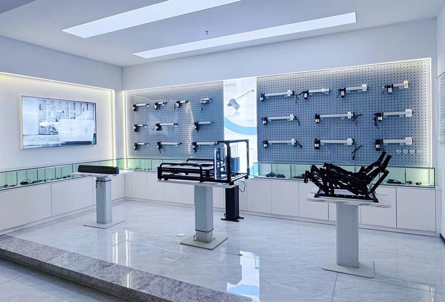
Synchronization acceptance should be verified on the assembled system against the project-defined test conditions.
ServoCylMotion First-Party Synchronization Context
ServoCylMotion's controlled YK controller data distinguishes standard multi-channel operation from documented synchronized models.
- YK-06: two synchronized channels, positioned for two-leg desks and similar paired-motor systems.
- YK-08: three synchronized channels for three-point motion applications.
- YK-10: four synchronized channels for four-point motion applications.
The controlled family platform is documented around DC 29V and 60–120W at family level, with FR4 PCB and ABS housing. These are family-level references, not proof that every maximum or option applies simultaneously to every configuration.
The current controlled source does not publish a universal feedback architecture, sensor type, or synchronization tolerance. Those items should be confirmed for the intended motor, controller, wiring, mechanical platform, and project requirement.
For model-level controller selection, review the wireless motor controller family . For electrical interfaces and component matching, use the system compatibility review .
Frequently Asked Questions
Why do two motors need synchronization in a standing desk?
Because the two driven sides support one shared worksurface. If their positions or speeds diverge too far, the desktop can tilt, the frame can rack, and mechanical resistance can increase.
Is synchronization the same as having two controller channels?
No. Channel count indicates how many driven outputs a controller can operate. Synchronization additionally requires a defined relationship between those channels, a way to detect or infer mismatch, and logic for correction, stopping, reference, and recovery.
Does every synchronized desk use Hall sensors?
No. Feedback and control architectures vary. Hall-effect sensing is one possible implementation, but other designs can use different position, rotation, current, or state information. The actual method should be confirmed for the selected system.
What causes a dual-motor desk to become uneven?
Possible causes include asymmetric loading, unequal friction, poor alignment, structural binding, cable or connector faults, one-sided stalls or obstructions, feedback problems, or loss of a valid reference. Troubleshooting should separate mechanical, electrical, and control causes.
What does re-homing do?
It re-establishes a known reference relationship for the system so the controller can resume coordinated movement from a valid state. The exact procedure is configuration-specific.
What synchronization tolerance should an OEM specify?
There is no single value that should be copied across all desks. Define the acceptable mismatch from the desk geometry, structural behavior, application, control design, and product requirements, then test it under documented load and operating conditions.
What should be tested before production release?
At minimum, verify initial alignment, full travel, representative load, asymmetric load, direction changes, stop/restart, power interruption, connectors and cables, defined fault/recovery cases, re-homing, repeat cycling, and the production end-of-line check.
References
- Autonomous — Dual-Motor Desk Engineering and Synchronization
- RightAngle Products — Single Motor vs. Dual Motor Standing Desk Reliability
- JIECANG — Single Motor vs. Dual Motor Standing Desks: Engineering & Sourcing Guide
- UpDown Desk — How Electric Standing Desks Work
Define the Synchronization Requirement Before Freezing the System
For an OEM program, document the motor count, moving load, load distribution, travel, acceptable side-to-side mismatch, reset and fault behavior, wiring and power constraints, and validation conditions before locking the electronics.
Then review the multi-motor synchronization capability against that requirement set.