Electric Cylinder vs Linear Actuator: Key Differences for Machine Design
Compare servo screw cylinders and packaged linear actuators by force, speed, duty, feedback, holding, mounting, and complete system needs.

An electric cylinder is usually a type of linear actuator: both create straight-line motion from electrical power. The useful engineering comparison is narrower. It is a choice between a servo-driven screw cylinder configured for programmable machine motion and a packaged DC rod or slider unit that combines a motor, gearbox, screw, limits, and optional feedback.
Choose between them by checking the complete operating point, required control, behavior after power loss, load guidance, and the parts needed around the actuator. The family name alone does not settle force, speed, precision, duty cycle, or cost.
Table of Contents
Key Takeaways
- The terms overlap. An actuator is the broadest category, a linear actuator produces straight-line motion, and a cylinder-style electric unit is one implementation.
- A servo screw cylinder is a strong candidate for programmable positions, motion profiles, coordinated axes, and process monitoring.
- A packaged DC unit is often suitable for straightforward extend/retract or intermittent positioning when its exact ratings and controls meet the mechanism.
- Neither architecture guarantees continuous duty, load holding, side-load capacity, or measured process force.
- Compare a defined load-speed-stroke-cycle point and the complete controls, mounting, and safety system.
Why the Product Names Overlap
Industry names are descriptive, not a universal classification standard. Joyce/Dayton describes an electric cylinder as a kind of actuator that converts electrical energy into linear motion, while Tolomatic groups rod-style, rodless, integrated-servo, and external-motor designs within a wider linear-motion range. Both manufacturer sources are listed in the references.
For this comparison, the two sides mean:
| Comparison side | Representative architecture | Typical decision context |
|---|---|---|
| Servo screw cylinder | Servo motor and drive, ball or roller screw, thrust rod, bearings, feedback, and either an inline or parallel motor arrangement | Programmable industrial motion, repeatable trajectories, coordinated axes, or force-related processes |
| Packaged DC rod or slider unit | DC motor, gearbox, lead/Acme or ball screw, rod or carriage, end limits, and model-specific feedback/control options | Endpoint motion, intermittent adjustment, lifting, opening, or positioning with simpler controls |
These are representative implementations, not hard definitions. A compact rod unit may include position feedback and onboard control. A servo cylinder may use an integrated motor, an inline external motor, or a fold-back motor with a belt or gearbox.
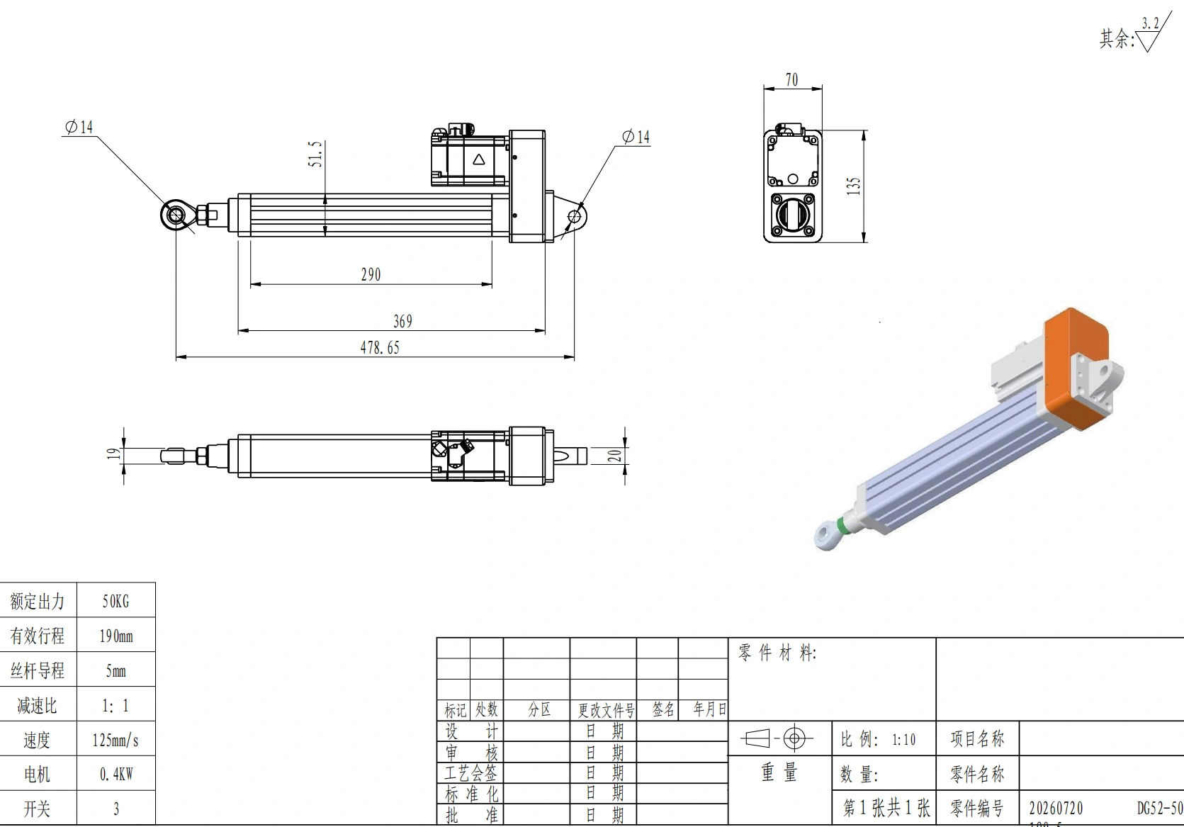
The DG52 drawing shows a screw cylinder with a parallel motor layout; the product name alone does not define its operating envelope.
Compare the Architecture Behind the Label
In a servo screw cylinder, the servo drive regulates motor motion from encoder or resolver feedback. The motor turns a screw directly or through a coupling, belt, or gearbox. The nut converts rotation into axial travel at the thrust rod. The drive and controller can command position, velocity, acceleration, and torque-related limits.
In a packaged DC unit, the housing normally contains the motor, reduction gearing, screw, nut, and output rod or carriage. A basic version may reverse by changing polarity and stop at end limits. Other models may add a potentiometer, Hall feedback, encoder, internal controller, or network interface. “Packaged DC” therefore does not mean “open loop” unless the exact model says so.
Tolomatic’s integrated-versus-traditional comparison, listed in the references, also shows why system boundaries matter. Removing an external motor mount may reduce couplings and alignment work, but the axis still needs compatible drive parameters, feedback, cables, controller logic, and commissioning.
| Design question | Servo screw cylinder | Packaged DC unit |
|---|---|---|
| Motor and drive | Servo motor plus compatible drive; motor may be integrated or externally mounted | Motor and reduction are usually inside the product; switching or a controller remains external unless built in |
| Motion conversion | Commonly ball or roller screw; exact screw and lead determine performance | Lead/Acme or ball screw depending on model and price/performance target |
| Position feedback | Normally part of the servo loop, with drive-specific compatibility | End limits may be standard; continuous position feedback is optional or model-specific |
| Intermediate positions | Suited to programmed positions and trajectories when correctly commissioned | Possible only with suitable feedback and controller |
| Mechanical packaging | More choices for motor, drive, gearbox, and mounting architecture | Compact self-contained package can simplify basic installation |
| Service boundary | Motor, drive, feedback, brake, screw, belt/coupling, and mechanics may be separate service items | Complete-unit replacement is common; internal repair options depend on the product |
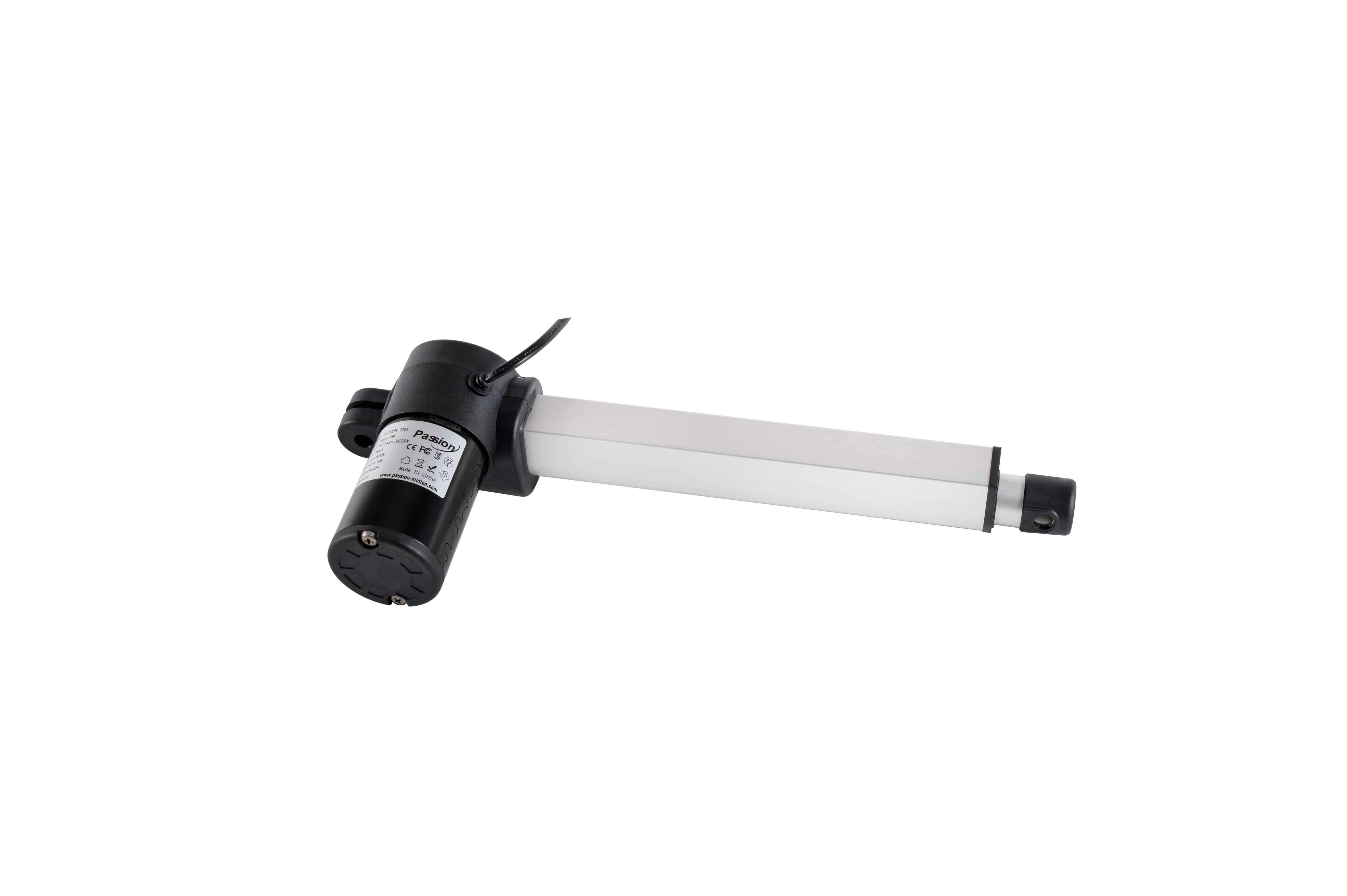
A packaged rod unit combines the motor, gearbox, tube, and end mounts in a compact assembly.
Decision Matrix for a Real Application
| Requirement | Favor a servo screw cylinder when… | Favor a packaged DC unit when… | Verify before selection |
|---|---|---|---|
| Motion task | The axis needs several positions, controlled acceleration, recipe changes, or coordination with other axes | The task is mainly extend/retract, lift/lower, or occasional repositioning | Position count, move profile, homing, synchronization |
| Force behavior | Force-related control or monitoring is part of the process and the sensing method is defined | The unit only needs to move within a known load envelope | Rated versus peak force, load-speed curve, sensor location |
| Cycle rate | A fully sized motor/screw/thermal system supports the specified production cycle | The documented intermittent rating fits the run-rest pattern | Load, speed, on-time, rest time, cycles/hour, ambient temperature |
| Power-off state | A rated brake or independent retention method is designed into the axis | A documented self-locking or brake-equipped model meets the holding requirement | Backdrive load, static holding rating, brake torque, failure response |
| Position performance | Published system accuracy and repeatability meet the process tolerance | Model-specific feedback and controller performance are sufficient | Accuracy, repeatability, resolution, backlash, load and temperature conditions |
| Side or moment load | The machine provides external guides or a rated guided configuration | The mechanism carries side load through hinges, rails, or bearings | Radial/moment ratings, full-stroke alignment, bracket freedom |
| Controls | The machine already uses a compatible servo platform or needs diagnostics and networked motion | A switch, relay, H-bridge, or compact controller completes the task | Voltage, current, drive, feedback, connector, fieldbus |
| Commercial case | Control capability, cycle performance, diagnostics, or changeover value justifies the full axis | Simple mechanics and controls keep the complete installation economical | Actuator, drive, controller, cables, sensors, guarding, setup, spares |
The “better” option is the one that closes every row at the required operating point. A simple unit with adequate feedback and duty rating can outperform an undersized servo axis in its intended task. A correctly sized servo axis can provide motion functions that would otherwise require extra switches, stops, or manual adjustments.
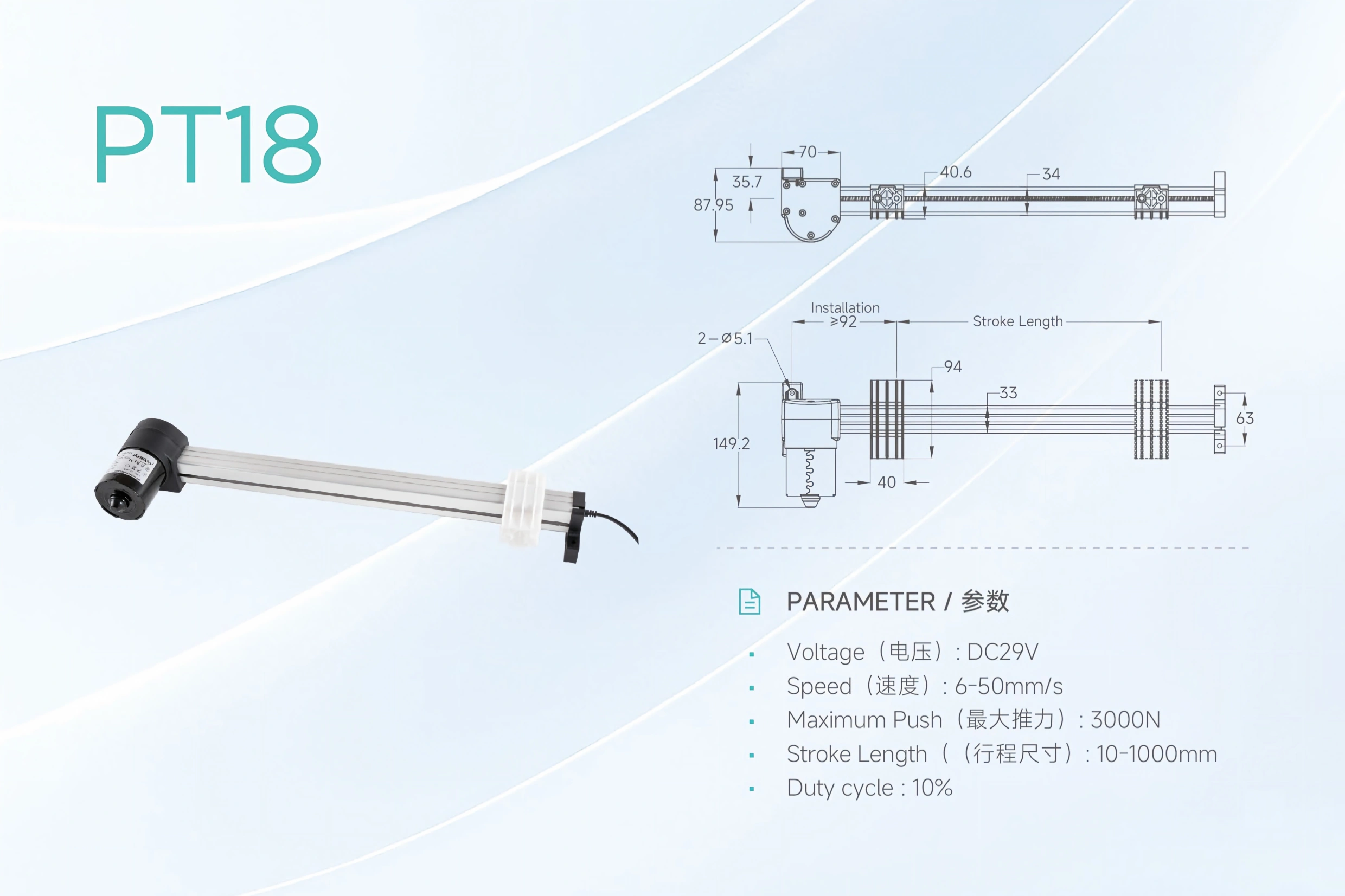
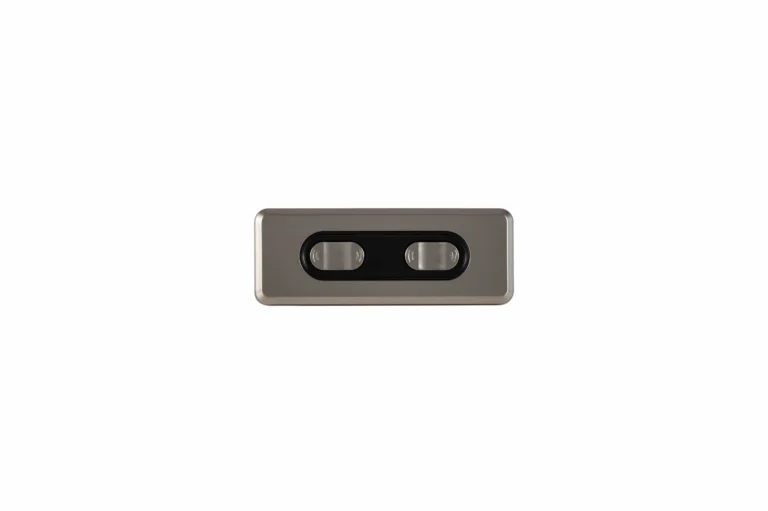
The PT18 slider layout shows why the broader category cannot be reduced to one cylinder-shaped form.
Read Every Specification as an Operating Point
Force, speed, stroke, and duty cycle are coupled. A larger screw lead can increase linear travel per revolution while reducing mechanical advantage. More reduction can raise available thrust while lowering speed. Longer screws can introduce buckling or critical-speed limits. Higher load and longer on-time increase heat in the motor, drive, bearings, screw, and grease.
That is why four numbers copied from separate range fields do not describe one usable configuration. Ask for the exact model’s force-speed curve or sizing result under the required stroke, orientation, acceleration, cycle, and ambient conditions.
ServoCylMotion’s documented examples illustrate the range of architectures and the limits of label-based assumptions:
| Example | Recorded force field | Stroke | Recorded speed | Other controlled data | What it demonstrates |
|---|---|---|---|---|---|
| DG52-50KG-190-5 | Rated output: about 490 N | 190 mm | Rated: 125 mm/s | 5 mm ball screw, 0.4 kW servo, fold-back motor | A servo screw cylinder can be configured for a light-load, higher-speed point |
| DG95-1.5T-250-5Z | Rated thrust: 15 kN | 250 mm | Rated: 83.3 mm/s | 5 mm ball screw, 1.5 kW servo, 1:2 reduction | A larger servo configuration combines higher rated thrust with a different motor and reduction |
| ZT01 | Maximum push field: 6000 N | 10–600 mm options | 6–40 mm/s listed range | DC 29 V, 10% duty cycle | A packaged rod unit can carry a higher headline force than a light-load DG example |
| PT18 | Maximum push field: 3000 N | 10–1000 mm options | 6–50 mm/s listed range | DC 29 V, 10% duty cycle, slider geometry | The broader family also includes carriage motion without a cylinder-style rod layout |
The DG values are rated fields, while the ZT01 and PT18 values are maximum/range fields. They are not equivalent test conditions and should not be ranked directly. Their practical lesson is that product naming does not create a force hierarchy.
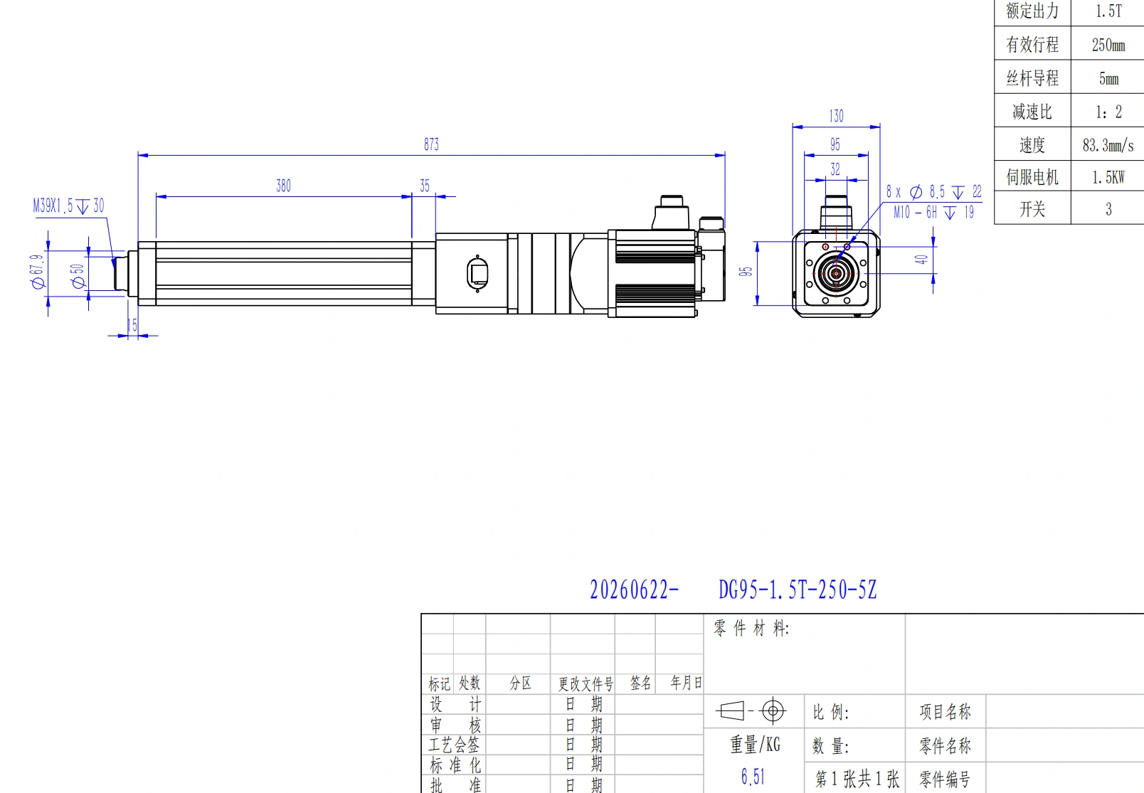
A controlled model drawing is needed to check the full installation envelope and mounting interfaces.
Five Checks That Prevent the Most Common Comparison Errors
1. Separate Position Feedback From Force Measurement
An encoder, resolver, Hall sensor, or potentiometer reports motion at a particular point in the system. It can support position control, speed control, and synchronization. It does not automatically measure the force at the workpiece.
Servo torque or motor current can provide a useful force estimate, but friction, acceleration, screw efficiency, belt tension, structural compliance, and temperature affect the result. If process force is a quality or safety variable, specify a calibrated load cell or force sensor and define where it is installed.
2. Define the Power-Off State
For a vertical or overhauling load, state what must happen after a power loss. A ball-screw axis may backdrive. A lead screw or gearbox may resist backdriving, but that behavior must be documented for the exact load and wear condition. A holding brake also needs a rated torque, control sequence, and failure analysis.
Do not use motor torque at zero speed as the only retention method. Where uncontrolled motion can injure a person or damage equipment, add appropriate mechanical support and a machine-level safety review.
3. Keep Side Loads Out of the Rod
A thrust rating describes axial work. Offset forces and moments can load the extension tube, nut, screw, seals, bearings, and gearbox. Use external rails, bearings, hinges, spherical joints, or a rated guided configuration to carry those loads. Check alignment through the entire stroke, not only at the retracted position.
The PT18 image above also shows why form factor matters: a moving carriage and a thrust rod create different load paths and mounting interfaces even when both produce linear motion.
4. Convert “Duty Cycle” Into a Motion Schedule
A percentage alone is incomplete. Define move time, dwell time, rest time, cycles per hour, load during each phase, acceleration, ambient temperature, and expected service life. Servo components can also overheat when the screw, motor, brake, or enclosure is undersized. A servo label is not a continuous-duty rating.
For the documented DG products, ServoCylMotion’s maintenance guidance calls for initial grease replenishment after 300 operating hours and subsequent replenishment every 2000 hours. It also calls for several unloaded low-speed cycles after greasing and timing-belt inspection on return-type layouts. Apply these instructions only to the products covered by that guidance.
5. Compare the Installed System
A component-price comparison can omit the parts that determine the project cost. Include the motor, drive, controller, power supply, cables, connectors, sensors, brake, mounting hardware, external guides, control enclosure, guarding, programming, commissioning, spare strategy, and maintenance access.
An integrated servo design may remove motor-mount hardware. A packaged unit may reduce wiring for a basic endpoint task. Either advantage can disappear when the application needs added feedback, synchronization, safety functions, or custom integration.
When Each Approach Usually Fits
A servo screw cylinder is usually the better starting point when the machine needs:
- repeatable intermediate positions or motion profiles;
- coordinated multi-axis motion;
- controlled acceleration and deceleration;
- process recipes or rapid changeover;
- motion diagnostics and industrial network integration;
- a defined force-related process with the correct sensing architecture;
- a motor, drive, and screw sized together for the production cycle.
A packaged DC rod or slider unit is usually the better starting point when the mechanism needs:
- simple extension and retraction;
- intermittent lifting, opening, tilting, or adjustment;
- endpoint control or modest position feedback;
- a compact, self-contained mechanical package;
- straightforward replacement as a complete unit;
- documented load, speed, duty, environment, and holding performance without a full servo platform.
For compact endpoint and slider architectures, review the available rod and carriage families against the same operating-point checklist.
What to Put in the RFQ
A useful request identifies the application before asking for a model:
- Load: moving, static, shock, friction, and worst-case linkage force in both directions.
- Motion: stroke, loaded speed, acceleration, deceleration, move time, and required positions.
- Cycle: moves per hour, on-time, dwell, rest, shifts per day, and ambient temperature.
- Geometry: retracted and extended length, mounting points, orientation, collision envelope, and external guidance.
- Performance: accuracy, repeatability, resolution, backlash, and acceptable deflection.
- Controls: supply voltage, servo platform or controller, feedback type, I/O, fieldbus, synchronization, and cable requirements.
- Force and holding: whether force is estimated or measured, sensor location, power-off state, brake, and independent load support.
- Environment and service: dust/water exposure, temperature, contamination, lubrication access, expected life, and replacement strategy.
If the load changes through a linkage, calculate the required operating point across the full travel before comparing model tables.
Frequently Asked Questions
Are an electric cylinder and a linear actuator the same thing?
The first is generally one implementation of the second. Vendor names overlap, so confirm the motor, transmission, output form, feedback, ratings, and control interface instead of classifying a product by its name alone.
Is a servo screw cylinder always more powerful?
No. Available force depends on the motor, drive, screw type and diameter, lead, gearing, stroke, bearings, thermal limits, and rating definition. Compare rated or continuous performance at the required speed and cycle.
Can a packaged DC unit stop at intermediate positions?
Yes, if the selected model provides suitable position feedback and works with a controller that closes the position loop. End switches alone only establish travel endpoints.
Does a servo encoder provide force feedback?
An encoder provides position or motion feedback. A drive may estimate force from motor torque or current, but measured workpiece force normally requires a documented force sensor or load cell and a defined calibration method.
Which option will hold a vertical load without power?
Either may hold if the exact configuration has sufficient self-locking behavior, a correctly sized brake, or another rated retention method. Neither category guarantees it. Specify the static holding load, backdrive condition, brake behavior, and failure response.
Is a servo cylinder suitable for continuous operation?
Only when the complete motor, drive, screw, bearings, lubrication, cooling, and motion profile have a continuous rating under the stated load and temperature. The servo control method alone does not establish duty capability.
What is the most important comparison document?
Use the exact model data sheet, force-speed or sizing output, dimensional drawing, control/feedback specification, and maintenance instructions together. No single headline specification describes the installed axis.
Move From Comparison to a Checked Configuration
Bring the load profile, stroke, loaded speed, cycle schedule, installation envelope, control method, and power-off holding requirement. Then review ServoCylMotion’s cylinder-family configurations against one complete operating point.