Electromechanical Press Axis Selection: Force, Stroke, Speed, and Process Control
Select an electromechanical press axis by force profile, stroke, approach and working speed, repeatability, stiffness, load-cell feedback, duty cycle, safety, and validation.

A pressing station should not be sized from a single force number. The press axis, servo drive, screw transmission, load cell, machine frame, tooling, fixture, and control logic form one process system.
For OEM engineers, the correct selection question is:
What force-position-time profile must the machine reproduce, measure, and verify over the required production cycle?
That profile determines the mechanical load, motor/drive demand, stroke, speed phases, stiffness requirement, sensing architecture, thermal duty, quality-monitoring strategy, and validation plan.
Table of Contents
Press-axis selection table
| Requirement | What to define | Why it matters |
|---|---|---|
| Peak process force | highest force during the working portion of the cycle | sizes the transmission, bearings, motor/drive and structure |
| Continuous / repeated load | force and duration repeated over the duty cycle | drives thermal suitability and service life |
| Stroke | approach distance + working travel + return clearance | prevents force-only sizing |
| Approach speed | motion before tool contact | affects cycle time and impact risk |
| Working speed | motion while force is building | affects process stability and force control |
| Return speed | retract motion after the process | contributes to total cycle time |
| Position repeatability | allowable variation in ram position | important for insertion depth and dimensional processes |
| Force repeatability | allowable process-force variation | important for consistent joining quality |
| Force sensing | load-cell range, calibration and overload | determines what the machine can measure directly |
| Force-position monitoring | acceptance windows and process signature | supports defect detection and traceability |
| Stiffness | frame, tooling, bearings, screw and fixture compliance | loaded deflection changes apparent position |
| Duty cycle | cycles/hour, force duration, dwell and ambient | determines thermal loading |
| Alignment | tool centerline, guide and fixture geometry | reduces side load and distorted measurements |
| Safety | guarding, interlocks, overtravel and fault behavior | separates process control from machine safety |
| Validation | calibration, repeatability, thermal, overload and lifecycle tests | proves the production-intent system |
Press-axis selection should start from the force-position-time profile, stroke, speed, stiffness, and duty cycle.
The table is intentionally process-first. It does not assume one transmission or one product size is correct for every press station.
Step 1: Build the force-position-time profile
Before selecting hardware, divide the cycle into phases.
A typical sequence is:
- rapid approach;
- contact detection;
- controlled working stroke;
- force/position verification;
- optional hold;
- retract;
- cycle result and data record.
For each phase, define:
- position range;
- speed;
- acceleration/deceleration;
- force;
- time;
- control mode;
- pass/fail condition.
This prevents a common mistake: combining maximum force and maximum speed as though both must occur simultaneously.
Example process logic
A press-fit process may require:
- fast approach until just before contact;
- slower controlled motion after contact;
- a maximum force limit;
- a required insertion distance;
- a force-at-position window;
- a final retract command.
The axis therefore needs more than “enough force.” It needs a motion and measurement architecture that supports the actual process recipe.
Step 2: Separate peak force from repeated thermal load
Peak force is the highest force the system may experience.
Continuous or repeated load is what determines much of the thermal and lifecycle requirement.
The sizing sheet should include:
- peak force;
- force duration;
- average/RMS motor load where applicable;
- cycles per minute or hour;
- dwell time;
- return time;
- ambient temperature;
- motor/drive thermal limits;
- screw and bearing life.
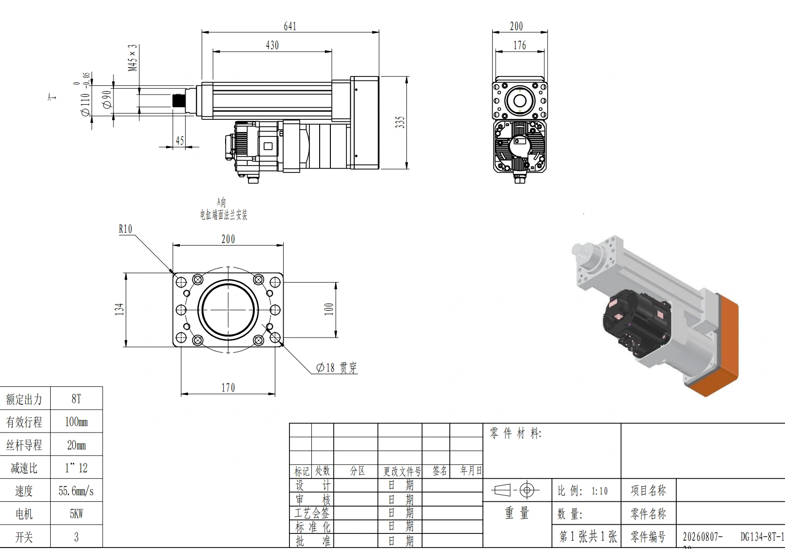
Peak force, continuous thermal load, stroke, and speed must be checked as a real operating profile rather than as unrelated maxima.
A high-force event that lasts a fraction of a second is different from holding a large load for most of the cycle.
Do not treat independent catalog maxima for force, speed and duty as one guaranteed operating point.
Step 3: Separate approach, working, and return speeds
Pressing cycles often need at least three speed regions.
Approach speed
The ram moves quickly toward the part before contact.
The design should consider:
- available clearance;
- moving mass;
- impact risk;
- contact-detection method;
- acceleration;
- deceleration before the working zone.
Working speed
After contact, speed is usually lower so the machine can control and monitor the process.
Requirements may include:
- force build rate;
- allowable overshoot;
- position resolution;
- force sampling;
- process-window response.
Return speed
After the process, the axis retracts.
A fast return can reduce cycle time, but the motion still needs:
- safe clearance;
- controlled deceleration;
- fixture/tooling protection;
- thermal consideration.
Step 4: Decide whether the process is position-led, force-led, or both
Different pressing processes use different acceptance logic.
Position-controlled with force monitoring
The axis moves to a target position while the system watches force.
Useful when:
- insertion depth is primary;
- force is a quality check;
- upper/lower force limits can identify abnormal parts.
Force-controlled with position limits
The axis builds to a target force while position is monitored.
Useful when:
- preload or clamp force is primary;
- part dimensions vary;
- travel must still remain inside a safe window.
Combined force-position acceptance
Many joining processes benefit from both.
Possible quality rules include:
- force at a specified position;
- position at a specified force;
- peak force inside a window;
- force rise over a distance interval;
- complete force-position curve inside an envelope.
Promess, Janome, IAI and Kistler all emphasize programmable motion and process monitoring as core elements of modern servo-driven pressing.
Step 5: Treat force measurement as a calibrated measurement chain
A dedicated load cell can provide direct process-force information, but only if the measurement chain is specified and maintained.
Define:
- sensor range;
- overload capacity;
- resolution;
- accuracy target;
- calibration interval;
- zero/tare behavior;
- mounting location;
- amplifier/interface;
- sampling rate;
- filtering;
- sensor-fault detection.
Motor current is not automatically tool force
Motor current can be useful for diagnostics or inferred load, but it is affected by:
- screw efficiency;
- bearings;
- lubrication;
- temperature;
- gearbox losses;
- acceleration;
- friction.
If traceable force measurement is required, the project should define the sensor and calibration method explicitly.
Step 6: Include frame and tooling stiffness in the position budget
The servo feedback may know motor or screw position very accurately while the tool moves less than expected under load.
Why?
Because the complete load path deforms:
- press frame;
- columns;
- bearings;
- screw;
- couplings;
- ram;
- tooling;
- fixture;
- workpiece.
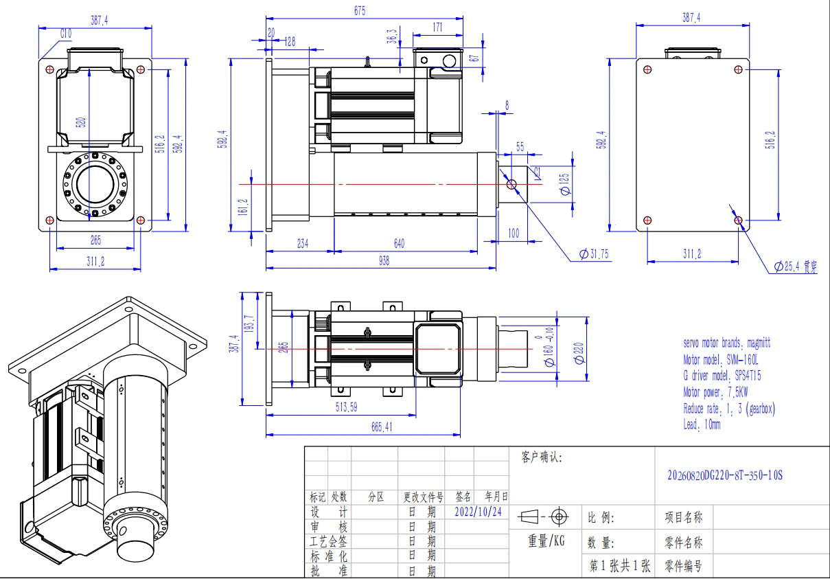
Machine frame, tooling, guides, bearings, and screw transmission all contribute to loaded stiffness and measured position.
Under high force, elastic deflection can become part of the measured process.
For better repeatability:
- keep the force path short;
- use a stiff frame;
- align the tool centerline;
- minimize eccentric loading;
- guide the tooling appropriately;
- control fixture stiffness;
- verify screw/bearing preload;
- account for thermal growth.
A high-resolution encoder cannot compensate for a flexible machine structure.
Step 7: Control alignment and side load
The press axis should primarily carry axial force.
The machine structure should manage:
- lateral guide loads;
- tooling moments;
- eccentric workpiece loads;
- fixture misalignment.
Check:
- guide parallelism;
- ram-to-tool alignment;
- fixture flatness;
- bracket stiffness;
- bearing loading;
- off-axis moments;
- tolerance stack.
Misalignment can increase wear, create side load, distort force readings, and reduce repeatability.
Step 8: Choose the screw and drive from the real duty profile
The screw transmission affects:
- force capacity;
- speed;
- efficiency;
- stiffness;
- backlash;
- life;
- lubrication;
- thermal behavior.
The correct choice depends on the force-speed-duty combination, not on a generic “best” screw type.
For broader sizing and selection support after the pressing requirements are frozen, use the engineering resources .
If a press process has unusual force, stroke or packaging constraints, the customization capability is the commercial bridge rather than expanding this article into a product page.
Step 9: Define quality windows and traceability
A production press may need to save:
- part ID;
- timestamp;
- recipe/parameter set;
- force-position curve;
- peak force;
- final position;
- cycle result;
- error code;
- calibration status;
- hardware/firmware revision.
This data can support:
- pass/fail decisions;
- process troubleshooting;
- trend monitoring;
- maintenance;
- traceability.
The acceptance window should be developed from validated good and bad process conditions rather than guessed from one successful sample.
Step 10: Include duty cycle and thermal validation
Production pressing can create a demanding thermal profile even when individual strokes are short.
Record:
- cycles per minute/hour;
- approach time;
- working time;
- hold time;
- retract time;
- force during each phase;
- ambient temperature;
- ventilation;
- motor/drive temperature limits.
The thermal test should reproduce the real cycle, not a simplified no-load motion pattern.
Step 11: Separate process limits from machine safety
Force control is a process function. Machine safety is a separate engineered layer.
The risk assessment may require:
- guarding;
- interlocked access;
- emergency stop;
- safe drive state;
- safe torque-off or equivalent where appropriate;
- overtravel protection;
- mechanical stops;
- load-cell overload protection;
- jam/stall behavior;
- controlled reset/restart;
- maintenance lockout.
Do not assume that a process-force limit alone makes an exposed press safe.
Step 12: Validate the complete pressing system
Before production release, test the actual frame, tooling, sensor, drive and control configuration.
Force and measurement
- calibrate the force sensor;
- verify zero/tare stability;
- test overload response;
- verify force repeatability;
- verify sampling and filtering.
Position and stiffness
- measure loaded deflection;
- verify repeatability at working force;
- check tooling alignment;
- evaluate backlash and compliance.
Process
- run worst-case part tolerances;
- verify force-position windows;
- test approach/work/return speeds;
- confirm cycle time;
- verify bad-part detection where required.
Thermal
- run the production duty profile;
- record motor/drive temperature;
- verify lubrication and screw behavior;
- inspect thermal drift.
Fault and safety
- test sensor loss;
- jam/stall;
- overtravel;
- power loss;
- reset/restart;
- interlock response.
Traceability
- verify data records;
- preserve recipe revision;
- record calibration status;
- identify exact hardware and firmware.
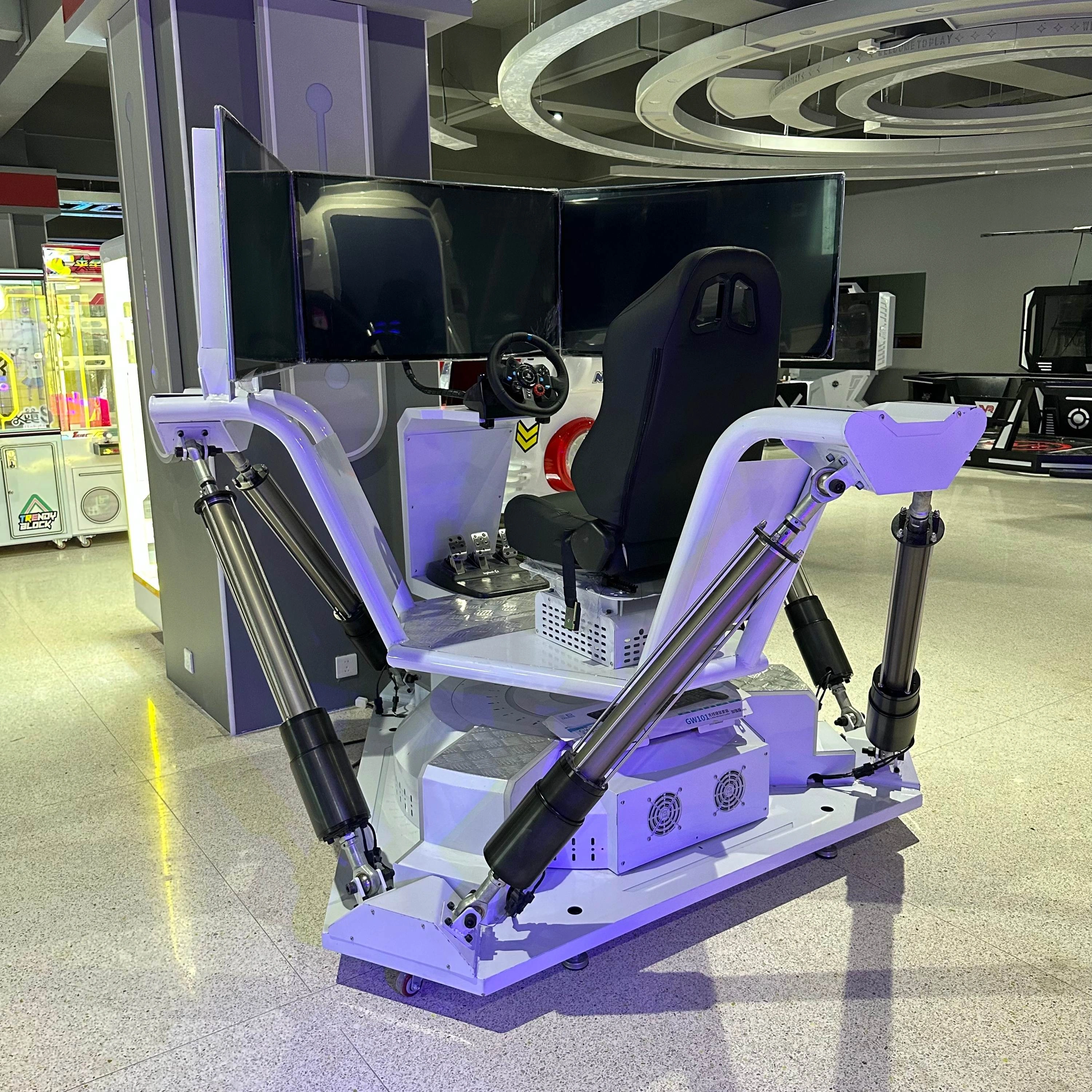
Production release should preserve the validated hardware, parameter, sensor-calibration, and revision state.
For early sizing, use the actuator sizing tool . For a production-intent application review, send the process profile, force range, stroke, cycle time, tooling geometry and monitoring requirements through ServoCylMotion contact .
FAQs
Should a press axis be selected from peak force alone?
No. Peak force is only one input. Stroke, approach and working speeds, duty cycle, stiffness, force sensing, repeatability, tooling alignment, and thermal load all affect suitability.
Why should approach and working speed be different?
Fast approach reduces cycle time, while slower working motion can improve contact control, force monitoring and process stability.
When is a load cell useful?
A load cell is useful when direct force measurement, force-based control, quality windows, or traceable force data are required.
Why can position change under load even with high-resolution feedback?
Because the machine frame, tooling, bearings, screw and workpiece deform elastically. Encoder resolution does not remove mechanical compliance.
Is motor current enough for force-quality monitoring?
Not always. Current is influenced by friction, efficiency, temperature and acceleration. Processes requiring calibrated force measurement should define an appropriate force sensor and calibration chain.
What should be validated before production?
Force calibration, force-position repeatability, loaded stiffness, process windows, alignment, duty/thermal behavior, overload/fault response, data logging, and lifecycle behavior should all be validated in the production-intent configuration.