Servo vs Stepper Linear Actuator: Which Drive Fits?
Compare servo and stepper linear actuator systems by feedback, speed-torque behavior, positioning, holding, heat, controls, and application fit.

A servo-driven linear actuator is usually the better fit when the axis must handle changing loads, aggressive acceleration, higher sustained speed, tight tracking, or costly position errors. A stepper-driven axis can be the simpler choice for predictable point-to-point motion when speed is moderate, load margin is conservative, and open-loop position assurance is acceptable.
The motor label is only the starting point. The real decision depends on the complete axis: motor, drive, feedback, screw or belt, gearbox, guides, load, motion profile, duty cycle, and behavior after power loss.
Table of Contents
Quick Decision: Servo, Open-Loop Stepper, or Closed-Loop Stepper
| Decision factor | Open-loop stepper | Closed-loop stepper | Servo |
|---|---|---|---|
| Position feedback | Commanded steps are assumed to occur | Encoder or other feedback detects error; correction behavior depends on the drive | Continuous feedback is normally part of the motion loop |
| Low-speed behavior | Strong holding and low-speed torque can be useful | Similar motor behavior with added error monitoring | Strong control at low speed, with performance depending on motor and tuning |
| Torque at higher speed | Usually falls significantly as speed rises | Feedback improves utilization but does not remove the motor's speed-torque roll-off | Usually provides a wider useful speed range |
| Disturbance recovery | Overload can create an untracked position error | May detect, correct, or fault depending on architecture | Corrects within available torque, bandwidth, and configured error limits |
| Commissioning | Usually simplest | Adds feedback setup and error thresholds | Requires motor-drive matching, feedback setup, and tuning |
| Thermal behavior | Holding current can create heat even at standstill | Current can often be reduced when lightly loaded | Current generally follows torque demand, but continuous torque still creates heat |
| Best starting point | Predictable point-to-point motion with conservative sizing | Moderate dynamics where silent position loss is unacceptable | Variable load, higher dynamics, coordinated motion, or high consequence of tracking error |
There is no universal winner. A well-sized stepper axis can outperform an undersized or poorly tuned servo axis in the job it was designed for.
Motor Type Is Only One Part of the Linear Axis
The phrase servo actuator is used broadly. In industrial motion, it usually describes a feedback-controlled system that includes a motor, drive, controller, feedback device, and the mechanical transmission that creates useful motion. The feedback may be mounted on the motor or closer to the moving load.
A stepper motor linear actuator can also describe several architectures: captive, non-captive, external screw, motorized lead screw, or a more integrated slide or cylinder. Some use open-loop control. Others add an encoder and closed-loop drive.
That distinction matters because the mechanics can dominate the result. A motor encoder may confirm motor-shaft position while backlash, screw lead error, coupling wind-up, guide friction, structural compliance, or thermal expansion remain downstream of the sensor.
A linear actuator should be evaluated as a complete axis, including motor, transmission, feedback, mounting, and load.
For a screw-driven axis, ask where position is measured and what parts of the mechanism are inside the feedback loop. A linear encoder at the carriage observes different errors than a rotary encoder mounted on the motor.
Speed, Force, and Acceleration Are Coupled
A motor does not have one torque value that applies at every speed. The useful comparison is the torque-speed curve for the exact motor and drive, translated through the selected screw, belt, or gearbox into the force-speed behavior of the axis.
For a screw-driven actuator, screw lead is one of the main trade-offs:
- A finer lead provides more mechanical advantage and more travel resolution per motor revolution, but requires more motor speed for the same linear velocity.
- A coarser lead produces more travel per revolution, but demands more motor torque for the same axial force.
- Gear reduction can increase output torque and reduce reflected load inertia, but it adds loss, backlash, compliance, and another mechanical element.
Stepper motors are attractive at low speed because they can provide useful holding and low-speed torque. As speed rises, winding inductance limits how quickly phase current builds, so available torque generally falls. That is why a stepper should be sized from the dynamic curve at the required speed rather than from its zero-speed holding-torque number.
Servo systems usually offer a wider dynamic envelope and greater transient torque capability for acceleration. They are often favored when the axis must move quickly, reverse frequently, coordinate with other axes, or recover from changing process loads.
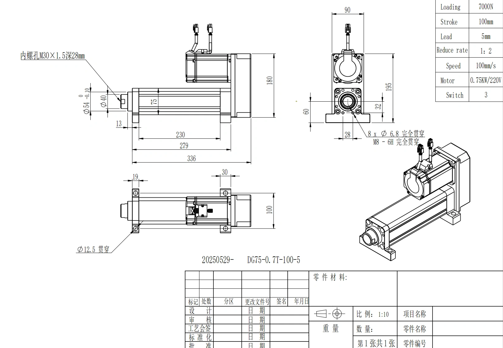
Motor torque, screw lead, transmission ratio, and motion profile jointly determine usable force and speed.
The motor still cannot be selected independently of the motion profile. Acceleration torque, reflected inertia, gravity, friction, process force, screw inertia, and duty cycle all contribute to the required operating point. Use the actuator sizing resource to organize these inputs before comparing drive types.
Positioning: Accuracy, Repeatability, and Resolution Are Different
Positioning discussions often become misleading because several terms are treated as if they mean the same thing.
- Resolution is the smallest commanded or measured increment.
- Accuracy is how close the actual position is to the target position.
- Repeatability is how consistently the axis returns to the same position.
- Backlash is lost motion when direction reverses.
- Settling time is how long the axis takes to enter and remain within the required position band.
A high encoder count does not automatically create an equally accurate machine. Likewise, microstepping does not turn every commanded microstep into an equally accurate mechanical position.
Open-loop steppers can be highly repeatable when the axis stays synchronized and the load is predictable. The risk is that an overload, resonance event, obstruction, or aggressive acceleration can cause lost synchronization. The controller may continue counting commanded steps even though the mechanical position has shifted.
A servo loop measures motion and reacts to the difference between command and feedback. This makes many position-loss conditions detectable and correctable, but only within the motor's available torque, the drive limits, the control bandwidth, and the mechanical system.
Feedback can correct only what the selected sensor and control loop can observe; mechanics still contribute to axis error.
Feedback location is critical. If the encoder is on the motor, the loop may not directly observe backlash, screw error, or compliance between the motor and the carriage. Load-side feedback can measure the actual linear output more directly, but it also adds integration and tuning requirements.
Error Recovery: Missed Steps vs Following Error
The practical difference between an open-loop stepper and a servo is often less about nominal positioning and more about what happens when the machine is disturbed.
An open-loop stepper assumes the requested move occurred. If the required torque exceeds the available dynamic torque, the axis can lose synchronization without immediately reporting the position error.
A servo drive continuously compares command and feedback. When the load changes, the drive can increase corrective torque within its limits. If the error becomes too large, the drive can produce a fault instead of silently accumulating position loss.
A closed-loop stepper sits between those cases. Depending on the drive, feedback may be used for stall detection, position correction, current optimization, or fuller real-time position control. These implementations are not equivalent, so ask exactly what the feedback does.
For a critical axis, verify:
- where the encoder is located;
- whether the drive detects or corrects error;
- what error threshold causes a fault;
- what happens after a temporary obstruction;
- whether the machine re-homes after a fault;
- whether a load-side position check is required.
Holding and Thermal Behavior Need Separate Checks
Stepper holding torque is useful, but it is often misunderstood. It is normally an energized zero-speed motor value. It does not by itself prove that a vertical load will remain safely in place after power is removed.
Power-off behavior depends on the complete mechanical system. A screw may be backdrivable or may resist backdriving depending on lead, friction, lubrication, wear, and load. A brake may be required for vertical or overhauling loads.
Servo axes need the same review. A servo can actively hold a position while powered, but continuous holding torque creates motor and drive heat. If the load must remain fixed after power loss, specify the brake or mechanical retention method separately.
Thermal behavior also differs by operating profile. Traditional open-loop stepper systems can draw substantial current at standstill. Closed-loop stepper drives may reduce current when the load is light. Servo systems generally regulate current according to torque demand, but continuous torque, repeated acceleration, and regenerative deceleration still require thermal and electrical sizing.
Do not select by efficiency claims alone. Compare the real cycle: moving time, dwell time, holding time, acceleration, load, ambient temperature, and cycles per hour.
Controls and Commissioning
An open-loop stepper axis is usually the simplest to commission. Typical work includes:
- motor current and supply voltage;
- step scaling or microstepping;
- acceleration and deceleration;
- resonance and vibration;
- homing and limit switches;
- torque margin across the required speed range.
A closed-loop stepper adds encoder alignment, feedback wiring, error thresholds, and correction behavior.
A servo axis normally adds motor-drive matching, encoder or resolver setup, gain and filter tuning, inertia and stiffness checks, and more detailed motion-profile validation. Auto-tuning can reduce setup time, but the machine still needs to be tested at its real load and operating conditions.
The complete wiring and control architecture can include motor power, feedback cable, brake wiring, I/O, fieldbus, limits, home sensors, and safety circuits. Compare cost at installed-axis level rather than from motor price alone.
When a Stepper-Driven Axis Is the Better Starting Point
Start with a stepper when most of the following are true:
- motion is primarily point to point;
- load and friction are predictable;
- speed and acceleration are moderate;
- conservative torque margin is acceptable;
- occasional homing or external position verification is practical;
- the cost and complexity of a full servo loop do not add enough value;
- low-speed holding behavior is useful;
- the process can tolerate the selected feedback strategy.
A stepper is not automatically a low-precision choice. The relevant question is whether the complete axis meets the required tolerance, speed, cycle, thermal limits, and error-detection needs under worst-case load.
When a Servo-Driven Axis Is the Better Starting Point
Start with a servo when one or more of these conditions dominates:
- load changes materially during the cycle;
- acceleration or reversal is aggressive;
- the axis must sustain higher speed under load;
- coordinated multi-axis motion is required;
- following error must be detected continuously;
- process throughput depends on short settling time;
- the consequence of an unreported position error is high;
- the machine needs richer motion diagnostics or programmable profiles.
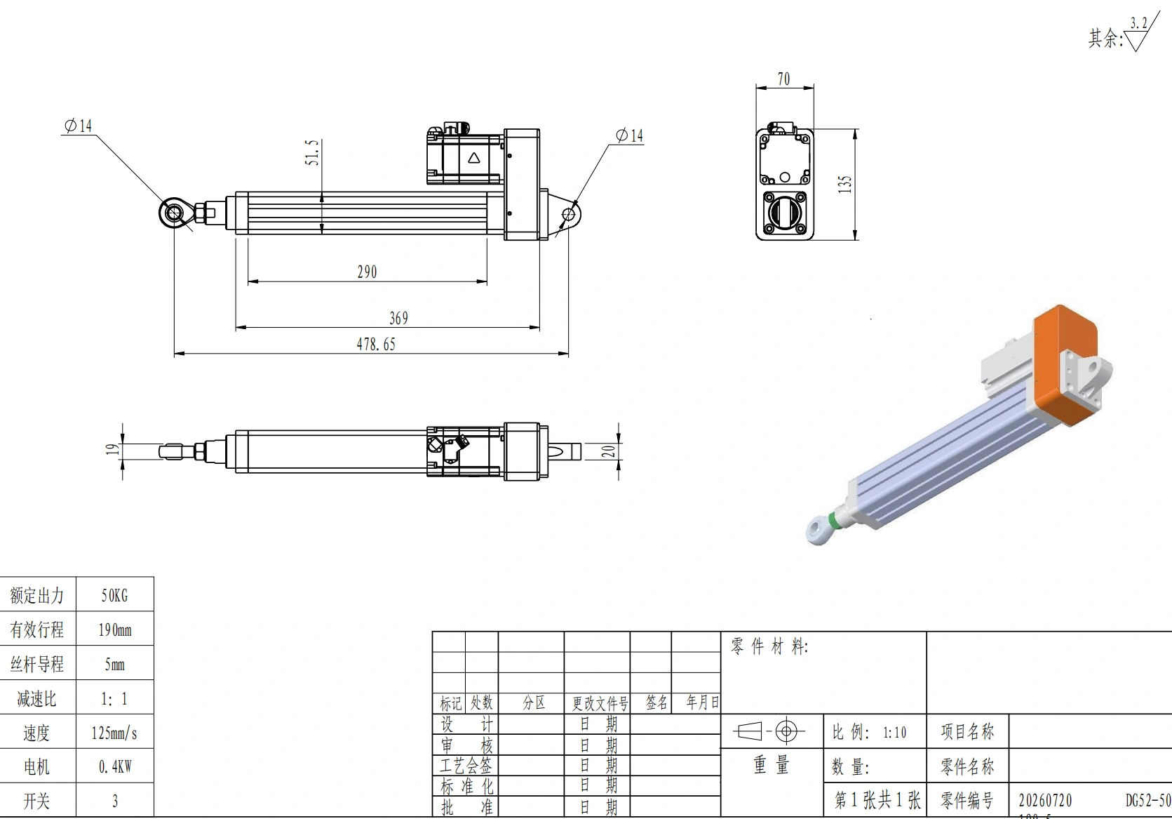
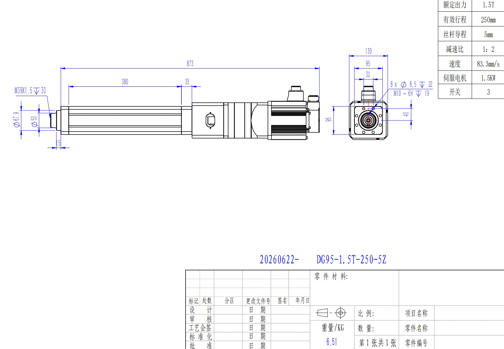
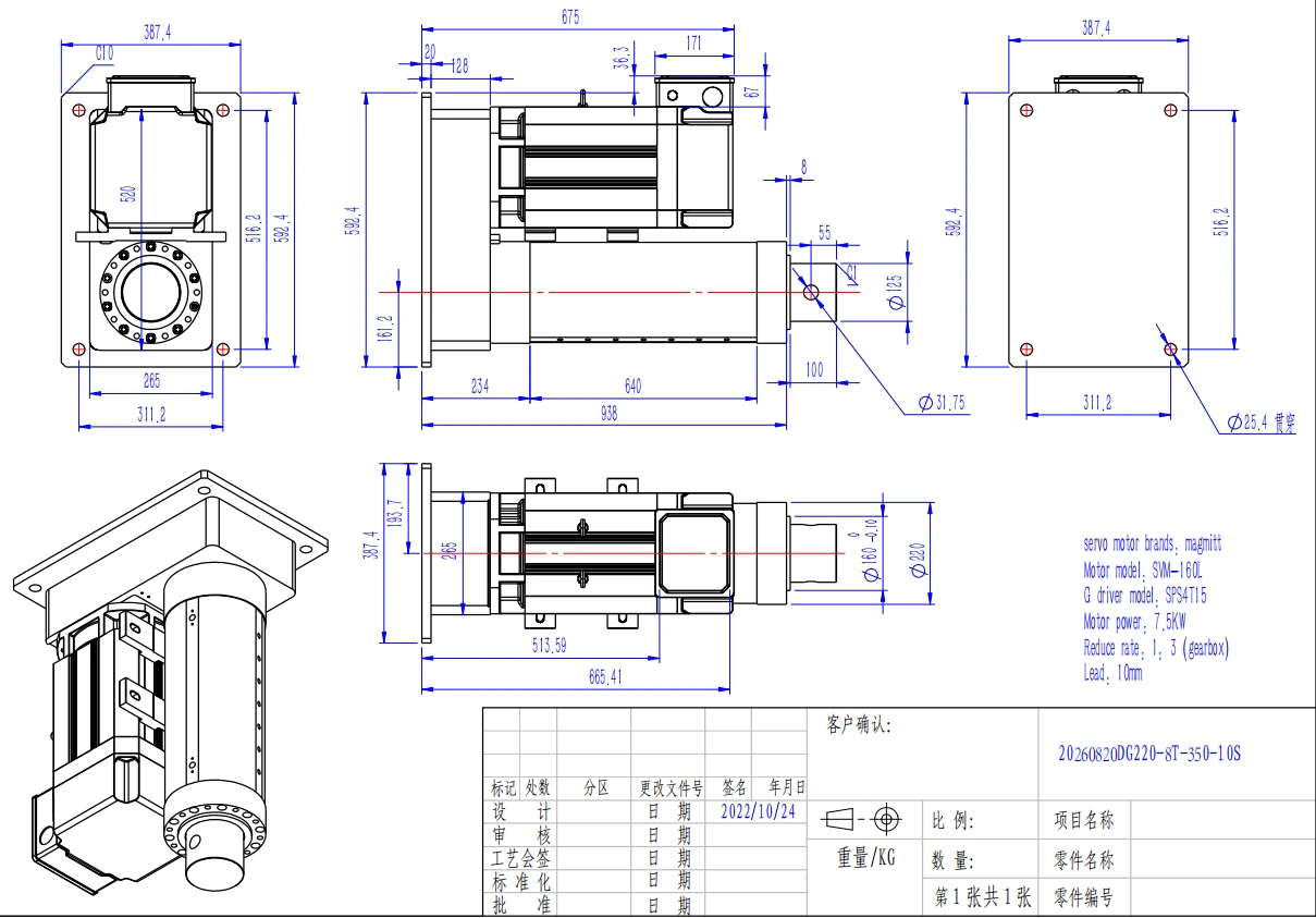
ServoCylMotion's DG-series documentation includes servo-driven screw-actuator configurations, so the electric cylinder family can be used as commercial context after the drive architecture has been defined. The comparison itself should still be made from the application operating point rather than from a family label.
Closed-Loop Stepper Changes the Old Binary
The old rule that stepper means open loop and servo means closed loop is no longer sufficient.
A closed-loop stepper can detect position error, reduce current when lightly loaded, increase corrective effort when needed, and report a fault when error exceeds a threshold. That can solve two common open-loop concerns: silent position loss and unnecessary heat.
It does not change every underlying motor characteristic. High-speed torque roll-off, resonance sensitivity, peak dynamic capability, and control bandwidth still depend on the motor and drive design.
When comparing a closed-loop stepper with a servo, ask:
- Is feedback used only to detect stall, or to correct position continuously?
- Is the encoder on the motor or on the load?
- What is the available torque at the required speed?
- What error causes a fault?
- What is the thermal behavior during long holds?
- How much tuning and commissioning does the system require?
Motion Requirements to Submit Before Choosing
Before selecting either drive type, define the complete application.
Final drive selection should be based on the required force, stroke, speed, acceleration, duty cycle, positioning tolerance, and operating conditions.
- Load and force: moving mass, external process force, friction, gravity, shock, and worst-case load.
- Stroke and geometry: required travel, retracted and extended envelope, mounting, guidance, and side/moment loads.
- Motion profile: loaded speed, acceleration, deceleration, move time, reversal frequency, and dwell.
- Duty cycle: moves per hour, holding time, run-rest pattern, and ambient temperature.
- Positioning: required accuracy, repeatability, resolution, backlash, and settling time.
- Feedback: motor-side or load-side position measurement, homing method, fault response, and position assurance.
- Power-off state: acceptable backdrive, brake requirement, and load-retention method.
- Controls: available voltage, drive/controller architecture, I/O, fieldbus, cabling, and safety functions.
- Environment: dust, moisture, contamination, temperature, maintenance access, and expected service interval.
If the requirements are not yet fixed, use the product selector to organize the motion task before narrowing the hardware.
Frequently Asked Questions
Can a stepper system be closed loop?
Yes. Encoder-equipped stepper systems can detect position error and, depending on the drive, correct the error, optimize current, or generate a fault. Verify the control behavior instead of assuming that every closed-loop stepper works the same way.
Is a servo always more accurate than a stepper?
No. The motor and control architecture matter, but so do screw lead error, backlash, guides, structural compliance, feedback location, tuning, temperature, and the test method. A well-designed stepper axis can meet demanding repeatability requirements, while a poorly designed servo axis can miss its target tolerance.
Does microstepping make a stepper proportionally more accurate?
No. Microstepping increases command granularity and often improves smoothness, but magnetic nonlinearity, friction, detent torque, backlash, screw error, and load variation limit real mechanical accuracy.
Can a stepper hold a vertical load when power is off?
Not from holding torque alone. Holding torque is normally specified while the motor is energized. Power-off load retention depends on screw backdrive behavior, brake design, gearing, friction, and the machine's independent safety strategy.
What matters more for linear positioning: motor type or screw mechanics?
Neither can be evaluated alone. The final result comes from the motor, drive, feedback location, screw or belt, bearings, guides, backlash, stiffness, thermal behavior, load, and tuning.
What information should be sent for drive selection?
Provide force or moving load, stroke, loaded speed, acceleration, cycle rate, orientation, positioning tolerance, feedback requirement, available controls/power, environment, and required behavior after power loss. These inputs allow both motor types to be compared at the same operating point.
Submit the Motion Requirements
For a real application, send the load, stroke, loaded speed, acceleration or cycle time, duty cycle, mounting orientation, positioning tolerance, feedback requirement, environment, and power-off holding requirement. Submit the motion requirements so the complete axis can be reviewed against one operating point.
References
- Tolomatic: Selecting a Stepper or Servo Motor for an Electric Linear Actuator
- Power & Motion: Getting the Right Stepper or Servo Motor for Electric Actuators
- Thomson: Stepper Motor Linear Actuator Driving Guide
- Texas Instruments: Closed-Loop Stepper Motor Design with Encoder for Stall Detection
- Rockwell Automation: Basics of Encoders for Motion Systems
- Oriental Motor: The Choice Between Servo Motors and Stepper Motors