Motor-Driven Linear Actuators: Definition & Working Principle
Learn how a motor, gearbox, screw, nut, rod, controller, limits, and feedback work together to create controlled straight-line motion.

A motor-driven linear actuator is an electromechanical motion unit that uses electrical power to create controlled straight-line force and travel. In a common screw-driven design, a motor turns a screw through gearing or a coupling; a restrained nut then moves a rod or carriage along one axis.
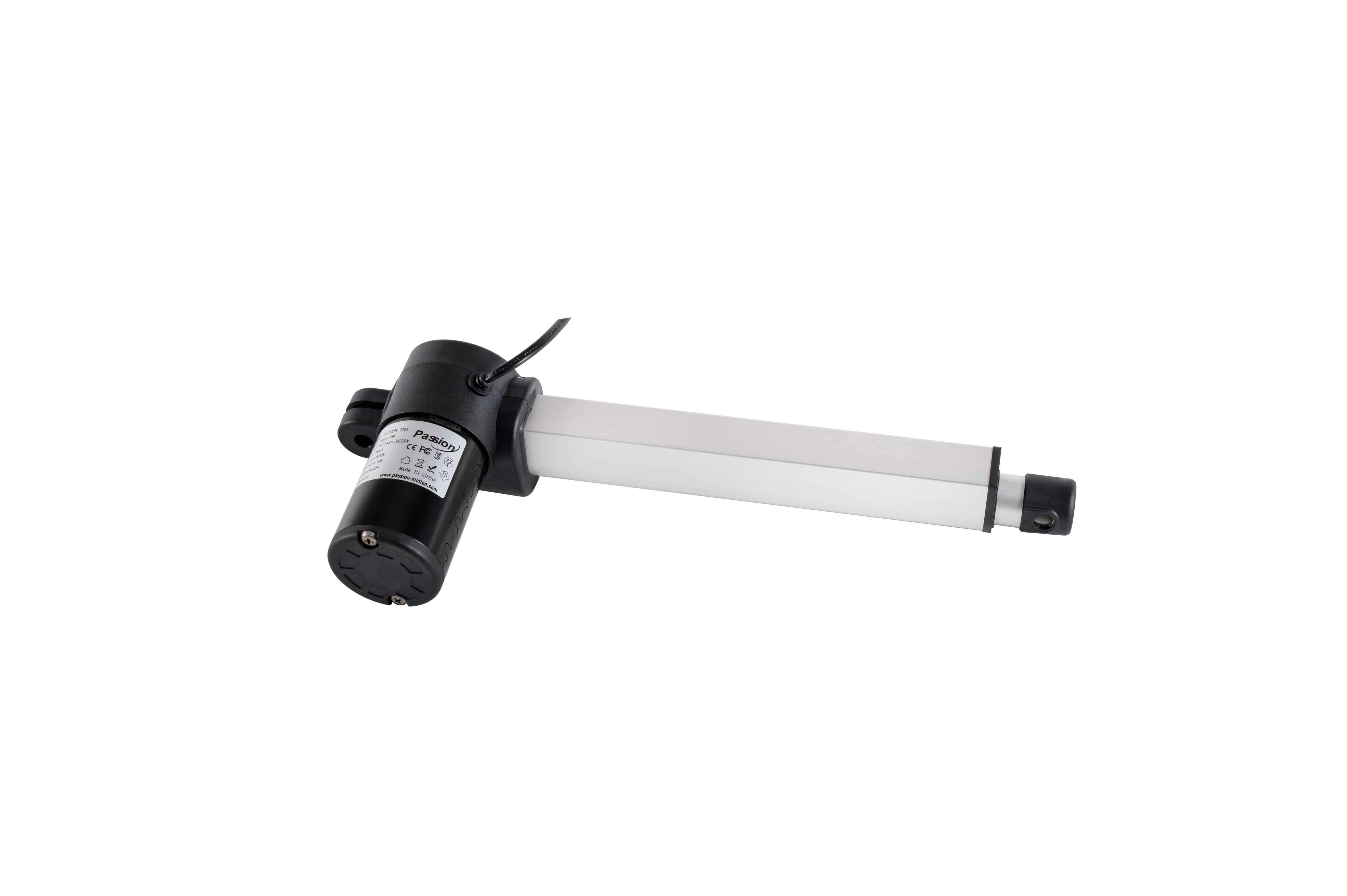
A typical packaged linear-motion unit combines a motor, transmission, housing, and moving output into one assembly.
The important idea is simple: the motor starts with rotation , while the machine needs linear movement . The actuator's mechanical transmission is what connects those two forms of motion.
Table of Contents
Key takeaways
- The motor produces rotary torque; it is not the entire motion subsystem.
- A gearbox or coupling transfers motor rotation to the mechanical transmission.
- In a common screw-driven design, the screw rotates while a restrained nut travels along its axis.
- The moving nut drives a rod or carriage that pushes, pulls, lifts, lowers, slides, or positions a load.
- Limit switches usually identify travel endpoints, while feedback devices can provide position or speed information between those endpoints.
- Screw drives are common, but belts, racks, direct-drive linear motors, and other mechanisms can also create linear travel.
How straight-line motion is created
A screw-driven mechanism can be understood as a seven-step chain.
- A command is given. A switch, relay, PLC, motion controller, or another control device requests movement.
- The motor is energized. The drive or switching electronics provide the current and voltage required by the motor.
- The motor develops rotary torque. Its shaft begins to turn.
- Rotation is transferred to the transmission. A gearbox may reduce speed and increase available torque, or a coupling may connect the motor more directly to the screw.
- The screw rotates. The screw thread creates a mechanical relationship between rotation and axial travel.
- The nut moves in a straight line. Because the nut is prevented from rotating with the screw, it travels along the screw axis and moves the attached rod or carriage.
- The motion stops or reverses. A command, endpoint device, or feedback condition tells the system when to stop, hold, or move in the opposite direction.
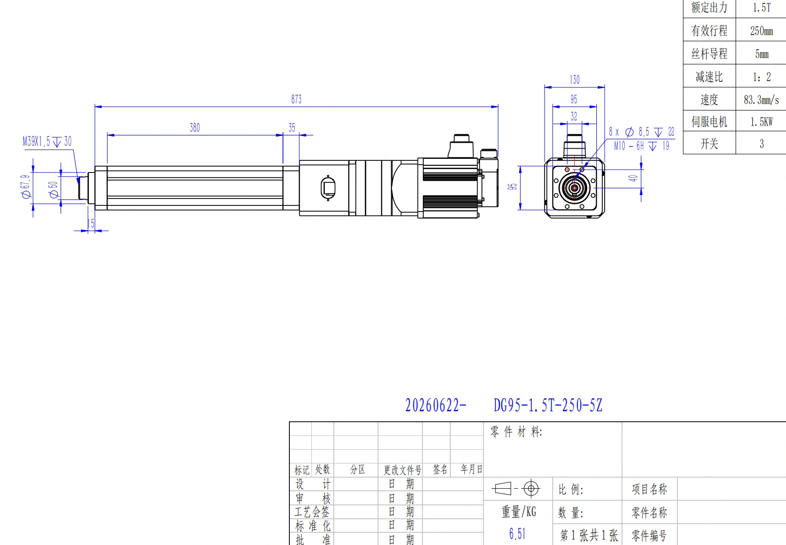
ServoCylMotion DG95 is one verified example of a servo motor driving a ball-screw transmission; other linear-motion designs can use different mechanisms.
ServoCylMotion's local product data provides two first-party examples of this architecture. DG52 is recorded with a precision ball screw, a servo motor, and three magnetic/proximity switches. DG95 is recorded with a servo motor and ball-screw transmission plus three limit/home proximity sensors. These examples show one verified implementation; they do not mean every linear-motion design uses the same screw, motor, or sensor arrangement.
What each component does
The mechanism is easier to troubleshoot and specify when each block has a clear job.
| Component | Primary job | What it does not automatically prove |
|---|---|---|
| Motor | Converts electrical input into rotary torque and speed | Final linear force, travel, or holding behavior |
| Gearbox | Adapts motor speed and available torque | A universal force or speed rating |
| Coupling | Transfers rotation between aligned shafts | That no gearbox is required |
| Lead, ball, or roller screw | Converts rotational input into axial nut travel | That every design uses a screw |
| Drive nut | Translates along the screw when rotation is constrained | Final accuracy without considering the complete system |
| Rod or carriage | Delivers usable straight-line output to the load | That it can carry arbitrary side loads |
| Housing and bearings | Support, align, and protect internal parts | A specific environmental rating |
| Limit switch | Detects or protects an endpoint | Continuous position measurement |
| Feedback sensor | Provides motion or position information according to sensor type | That closed-loop control is already implemented |
| Brake | Can help hold a shaft or load in designs that include one | That every unit holds safely when power is removed |
A useful mechanical relationship is that screw lead defines nominal travel per screw revolution . Motor speed, gearing, screw lead, efficiency, friction, load, and thermal limits then influence actual motion. That relationship explains the mechanism; it is not a substitute for model-level performance data.
Motor, drive, controller, and actuator are different blocks
These terms are often mixed together in procurement discussions, even though they describe different functions.
| Block | Main function | Typical question it answers |
|---|---|---|
| Power supply | Provides electrical energy | Is the required power available? |
| Controller | Decides what motion should happen | Where, when, and how should the axis move? |
| Drive / power electronics | Regulates or switches power to the motor | How should the motor be energized? |
| Motor | Produces rotary torque and speed | What rotary input is available? |
| Mechanical actuator | Converts that input into the required output motion | How does the load move in a straight line? |
| Machine structure and guides | Supports the load and controls its physical path | How is the moving load constrained and aligned? |
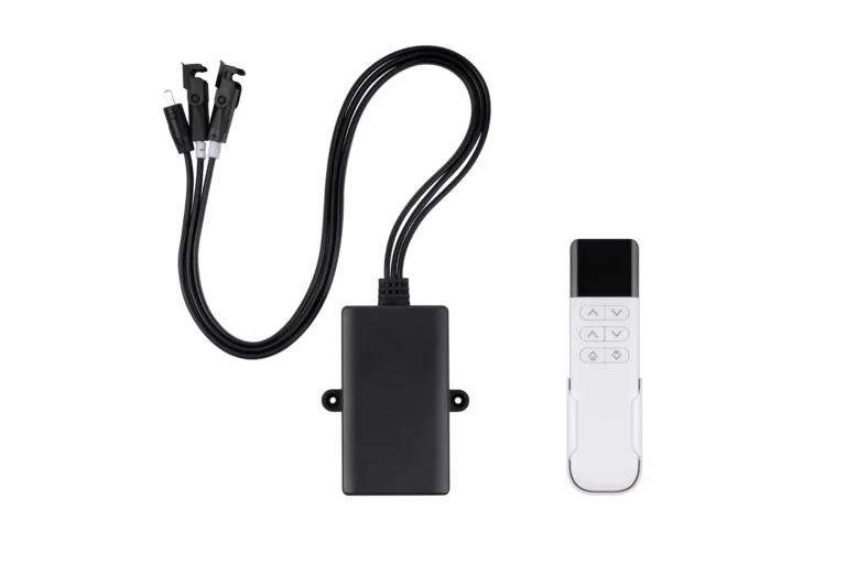
Commercial products can integrate several of these blocks into one assembly. Others expose the motor, drive, controller, feedback, or power supply as separate components. For B2B integration, the product label alone is not enough; the interface and included functions must be checked.
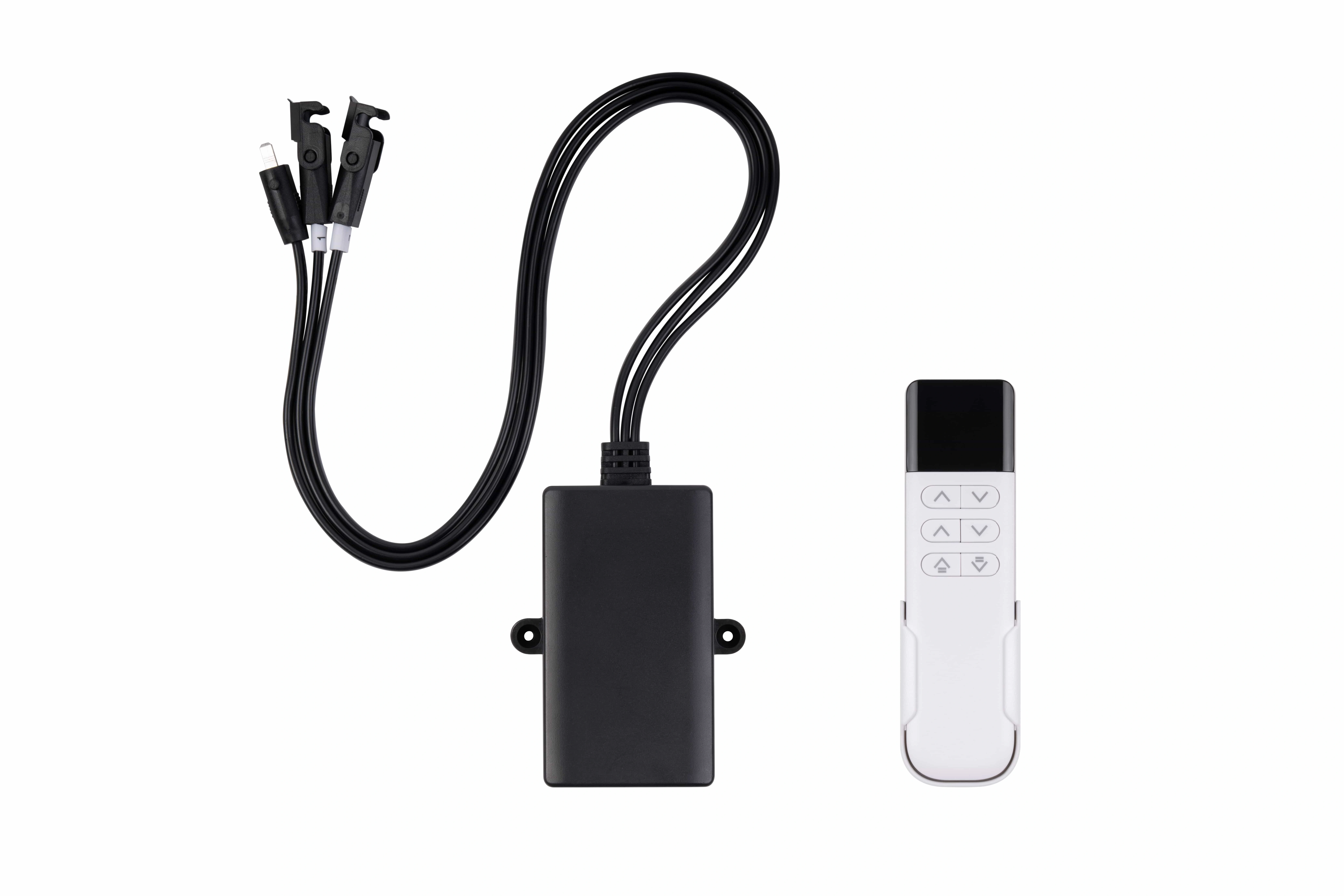
Control hardware tells the powered motion system what to do; the motor and mechanical transmission still perform the physical movement.
How direction reverses
To extend and retract a screw-driven unit, the transmission must move in opposite directions.
For a simple two-wire DC motor, reversing polarity reverses motor rotation. The screw then rotates in the opposite direction, so the restrained nut travels back along the axis. A reversing switch, relay arrangement, or motor driver can perform that change.
AC, brushless, stepper, and servo systems normally reverse direction through their drive electronics rather than by a simple two-wire polarity swap. The mechanical principle is still the same: reverse motor rotation, and the linear travel reverses .
Limit switches and position feedback are not the same thing
Endpoint protection and position measurement solve different problems.
| Device | Typical information | Common role |
|---|---|---|
| Limit switch | An end of travel has been reached | Stop or inhibit movement beyond an endpoint |
| Home/reference sensor | A known reference point has been detected | Establish a repeatable machine reference |
| Potentiometer | An analog signal related to travel position | Estimate position over the stroke |
| Hall sensor | Magnetic pulses or position-related information, depending on design | Motion counting or feedback |
| Motor encoder | Motor shaft position and/or speed | Closed-loop motor control or inferred axis position |
| Linear encoder | Direct output-axis position | Measure carriage or rod position more directly |
A motor encoder and a linear encoder are not necessarily interchangeable. If the system measures only the motor shaft, mechanical backlash or compliance can exist between that measurement point and the final load. Which sensor is appropriate depends on what the controller actually needs to know.
Why the screw example is not universal
A rotating screw and translating nut form a common architecture, but they are only one way to make linear motion.
- Screw-driven systems may use lead screws, ball screws, or roller screws.
- Belt-driven systems translate pulley rotation into carriage travel.
- Rack-and-pinion systems convert pinion rotation into motion along a rack.
- Direct-drive linear motors or voice-coil designs generate linear force without first converting rotary motor motion through a screw.
The right architecture depends on the application, but comparing those tradeoffs in depth belongs to a separate selection task. For this definition page, the key point is that the word “actuator” describes the output job, not one mandatory internal mechanism.
Product architecture, sensing, and included control functions should be confirmed against the exact configuration and controlled documentation.
ServoCylMotion's linear-motion product family includes different product forms, so the exact transmission, sensing, interfaces, and control requirements should be confirmed from the relevant model documentation rather than inferred from a generic diagram.
Five misconceptions to avoid
1. “The motor and the actuator are the same component.”
A motor primarily produces rotary torque. The linear-motion subsystem adds the transmission, output hardware, support structure, and sometimes feedback or limit devices needed to turn that rotation into controlled travel.
2. “Every design uses a lead screw.”
No. Screw-driven mechanisms are common, but belt, rack, direct-drive, and other architectures also exist.
3. “A limit switch tells me the exact position.”
Usually not. A limit switch normally indicates an endpoint. Continuous or intermediate position information requires a suitable feedback method.
4. “The load will always stay in place when power is removed.”
Holding behavior depends on transmission geometry, gearing, friction, load direction, brake provision, and other design details. Power-off holding should be verified for the exact configuration rather than assumed.
5. “The output rod can also guide any sideways load.”
A rod-style output is commonly intended to transmit axial push/pull force. If the machine imposes side loads or moments, the guidance arrangement and permissible loading must be checked separately.
What this means for an engineer or technical buyer
Mechanism understanding should come before model comparison. Once the energy-to-motion chain is clear, the next job is to define the application's required load, travel, loaded speed, duty, mounting geometry, environment, control method, and feedback behavior.
That requirement set belongs in the selection stage rather than this definition article. You can continue through the ServoCylMotion engineering guide library and move to the product selector only after the application inputs are sufficiently defined.
Frequently asked questions
What is the simplest way to describe a motor-driven linear actuator?
It is a powered mechanical subsystem that converts motor-driven rotation or another electrical motion mechanism into controlled movement along a straight line.
How does a screw-driven unit convert rotation into linear travel?
The motor turns the screw directly or through gearing. A nut is prevented from rotating with the screw, so the thread geometry makes the nut move along the screw axis. That moving nut drives the output rod or carriage.
Why is a gearbox used?
A gearbox adapts the motor's rotational speed and available torque before the motion reaches the screw or another transmission element. The resulting linear performance still depends on the complete configuration and load.
How does the unit move in the opposite direction?
The motor rotation is reversed. Simple DC systems may do this by reversing polarity; other motor technologies normally reverse through their drive electronics.
Do limit switches provide continuous position feedback?
No. Their normal job is endpoint detection or protection. A potentiometer, Hall device, encoder, or another suitable sensor is needed when the control system must know position between endpoints.
Will a screw-driven unit hold its load after power is removed?
Not necessarily. Holding depends on screw geometry, gearing, friction, external load, orientation, and whether a brake or another holding method is present. Verify this behavior from the exact product data and system design.
What should I define before comparing models?
At minimum, define the load, required travel, loaded speed, duty/cycle pattern, mounting geometry, environment, power/control interface, and feedback requirement. Those inputs turn a general understanding of the mechanism into a usable selection brief.
References
- Actuonix — actuator components and working principle
- LINAK — linear actuator working principle
- Haydon Kerk Pittman — linear actuator fundamentals
- JHFOSTER — actuator system components
- TiMOTION — linear-motion mechanism overview
- Rollon — linear transmission architectures
Next step
Once the mechanism is clear, turn it into an application requirement set before narrowing products. That keeps the next decision grounded in the load, motion, geometry, duty, environment, and control needs that actually determine fit.