DG95 15 kN Servo Actuator | 250 mm Stroke
DG95-1.5T-250-5Z servo linear actuator with 15 kN rated thrust, 250 mm stroke and 83.3 mm/s rated speed for precision industrial motion.
15 kN in a 95 mm body. Engineer the load path first.
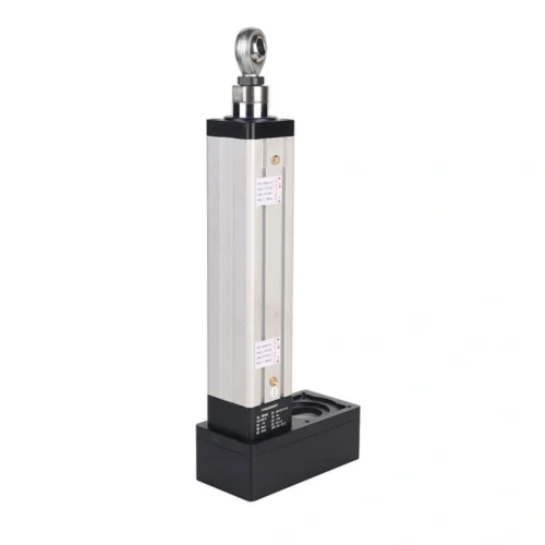
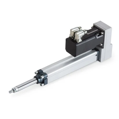
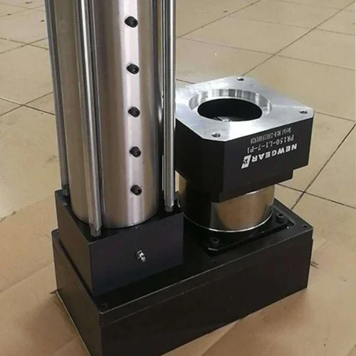
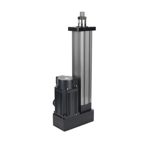
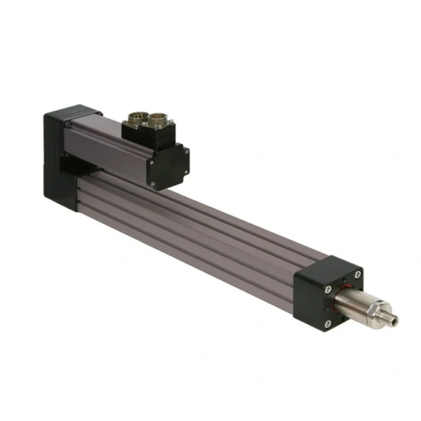
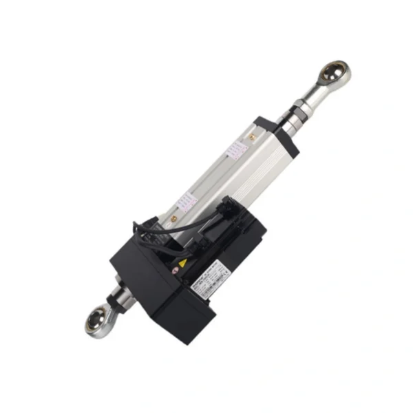
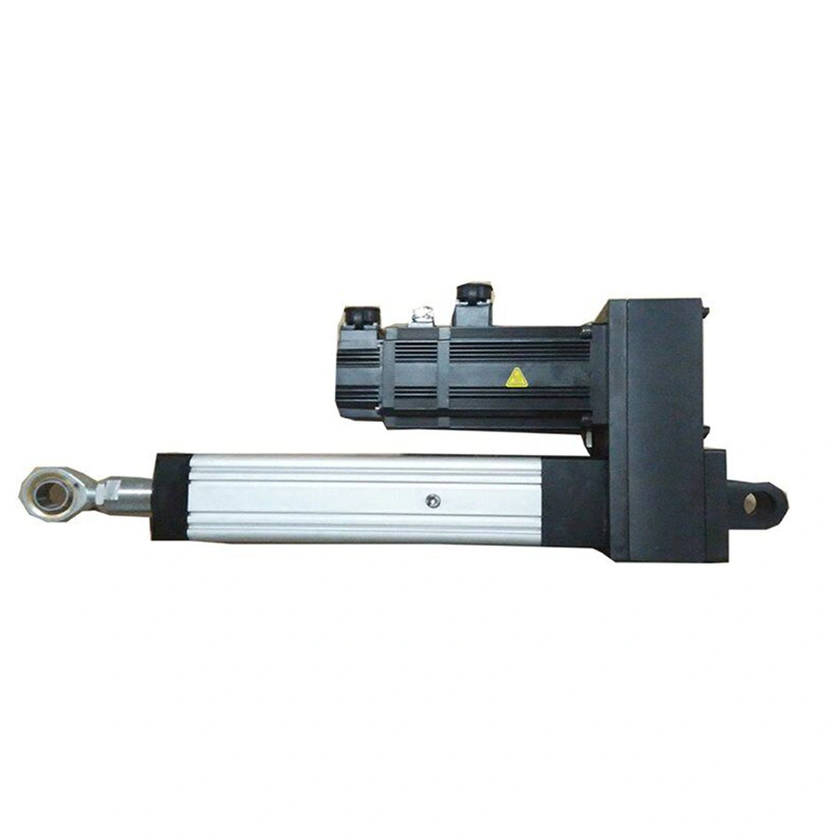
DG95-1.5T-250-5ZDG95 is a rod-style ball-screw servo axis documented for 15 kN rated thrust , 250 mm effective stroke and 83.3 mm/s rated speed , with a 1.5 kW servo motor, 5 mm lead and 1:2 reduction.
Change the load case and watch the engineering priority change with it.
The state graphic is illustrative, not a stress calculation. It exists to separate axial motion from side-load and vertical-holding questions before the machine structure is frozen.
Axial push keeps the rod near its intended load path.
Treat the rod primarily as an axial force-transmission member. Confirm the real working and peak loads, required loaded speed and cycle profile before release.
Review DG95-1.5T-250-5Z as one concrete configuration.
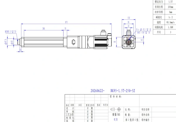
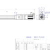
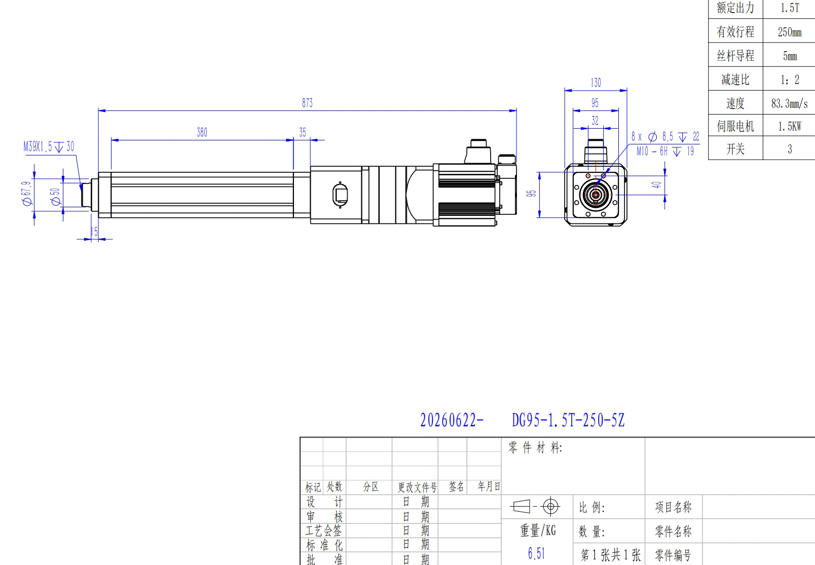
Before designing mating parts, request the current released drawing so dimensions, tolerances, cable orientation and mounting details can be checked against the machine revision.
| Parameter | Project value |
|---|---|
| Rated thrust | 15 kN / 1.5 ton |
| Effective stroke | 250 mm |
| Rated speed | 83.3 mm/s |
| Ball-screw lead | 5 mm |
| Reduction ratio | 1:2 |
| Servo motor power | 1.5 kW |
| Piston rod diameter | Ø50 mm |
| Rod-end thread | M39 × 1.5, 30 mm thread depth |
| Front step diameter | Ø67.9 mm |
| Body profile | 95 × 95 mm |
| Retracted overall length | 873 mm |
| Front body length | 380 mm |
| Overall height with motor housing | 130 mm |
| Mounting interface | 8 × Ø8.5, 22 mm depth / M10-6H, 19 mm depth |
| Proximity switches | 3 |
| Approx. weight | 6.51 kg |
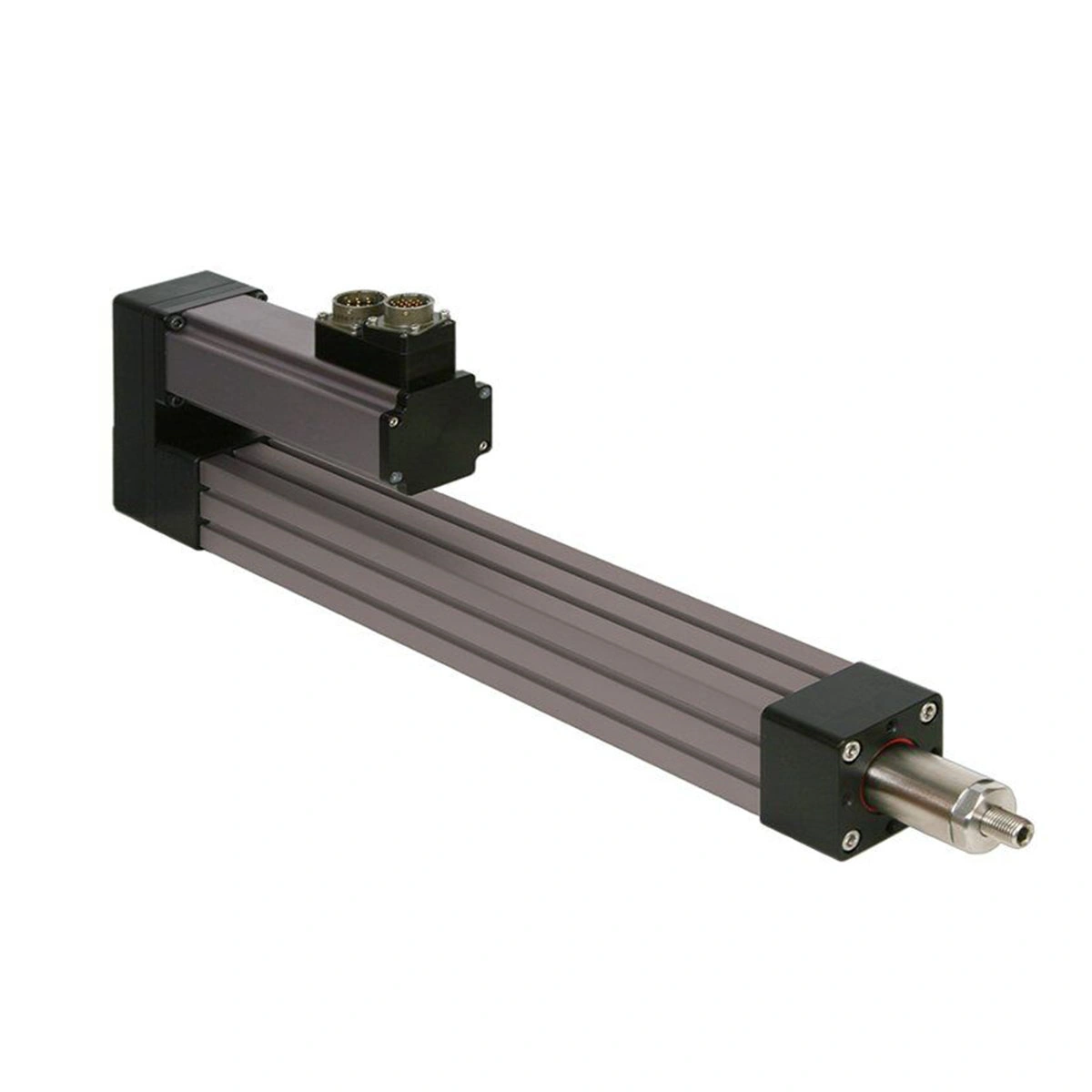
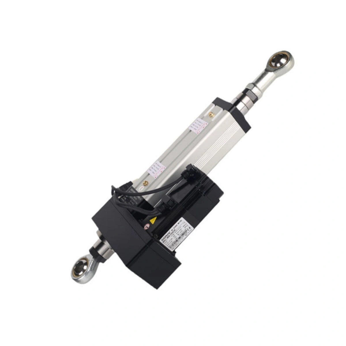
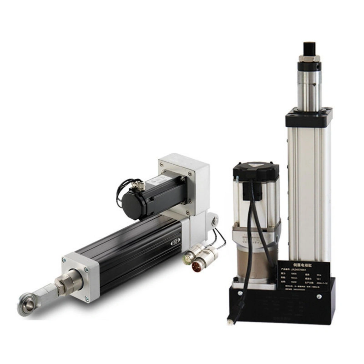
Use the 95 mm body and rod-end geometry as a layout reference, then release the interfaces from the drawing.
Offset loads, side loading, long unsupported tooling or overturning moment should be carried by the machine structure and external guidance rather than assumed acceptable at the rod.
Force, stroke and speed are three different questions—not one universal operating point.
The locked DG95 data labels 83.3 mm/s as rated speed but does not provide a full force-speed curve. Specify the speed required at the actual working load for configuration review.
Give engineering the complete machine context, not just “15 kN”.
Providing these inputs early helps distinguish a straightforward configuration check from a project that may need a different screw, drive ratio, support arrangement or axis size.
| Selection input | What to provide |
|---|---|
| Load direction | Push, pull, vertical, horizontal or angled. |
| Working load | Normal load plus known peak or transient load. |
| Speed under load | Target speed at the stated working load. |
| Travel | Required working stroke and any reserve. |
| Motion profile | Acceleration, deceleration, dwell and starts per cycle. |
| Cycle profile | Cycles per minute or hour and operating duration. |
| Load geometry | Side load, offset, tooling mass and external guidance. |
| Installation space | Available length, width, height and mounting constraints. |
| Control | Controller or drive platform, homing and limit requirements. |
| Environment | Temperature, dust, moisture, washdown or clean-area needs. |
| Holding requirement | Behavior required during stop or power loss. |
| Documents | CAD, drawing, wiring, test or quality documents. |
| Commercial input | Project quantity, sample need and target schedule. |
DG95 is strongest when load, motion, mounting, sensing and documentation are reviewed as one axis.
Send the working load, required speed under load, 250 mm travel confirmation, cycle profile, installation drawing, control platform, environment, holding requirement, quantity and required documents for project review.
Mechanical facts first; application release second.
DG95 is a documented 15 kN, 250 mm-stroke servo actuator configuration. Project-specific operating, holding, environment and lifecycle conditions still need confirmation.
Is 15 kN the documented DG95 rating?
Yes. The local DG95 record lists 1.5 ton / 15 kN as the rated thrust for DG95-1.5T-250-5Z. The working-load and cycle profile should still be reviewed for the application.
What is the usable travel?
The documented effective stroke is 250 mm.
Is 83.3 mm/s a no-load or loaded value?
The project record labels it as rated speed but does not provide a full force-speed curve in the locked evidence. Specify the speed needed at the actual working load for configuration review.
Do the three proximity switches provide servo feedback?
No. They are discrete proximity devices for limit or reference functions. Closed-loop servo feedback is a separate control function.
Can the axis be used vertically?
Vertical motion is a relevant application category, but holding, brake, counterbalance, guidance and machine-safety requirements must be reviewed for the specific installation.
What should be confirmed before machining brackets?
Request the current released dimensional drawing and verify the mounting pattern, rod-end interface, tolerances, and cable or motor orientation.