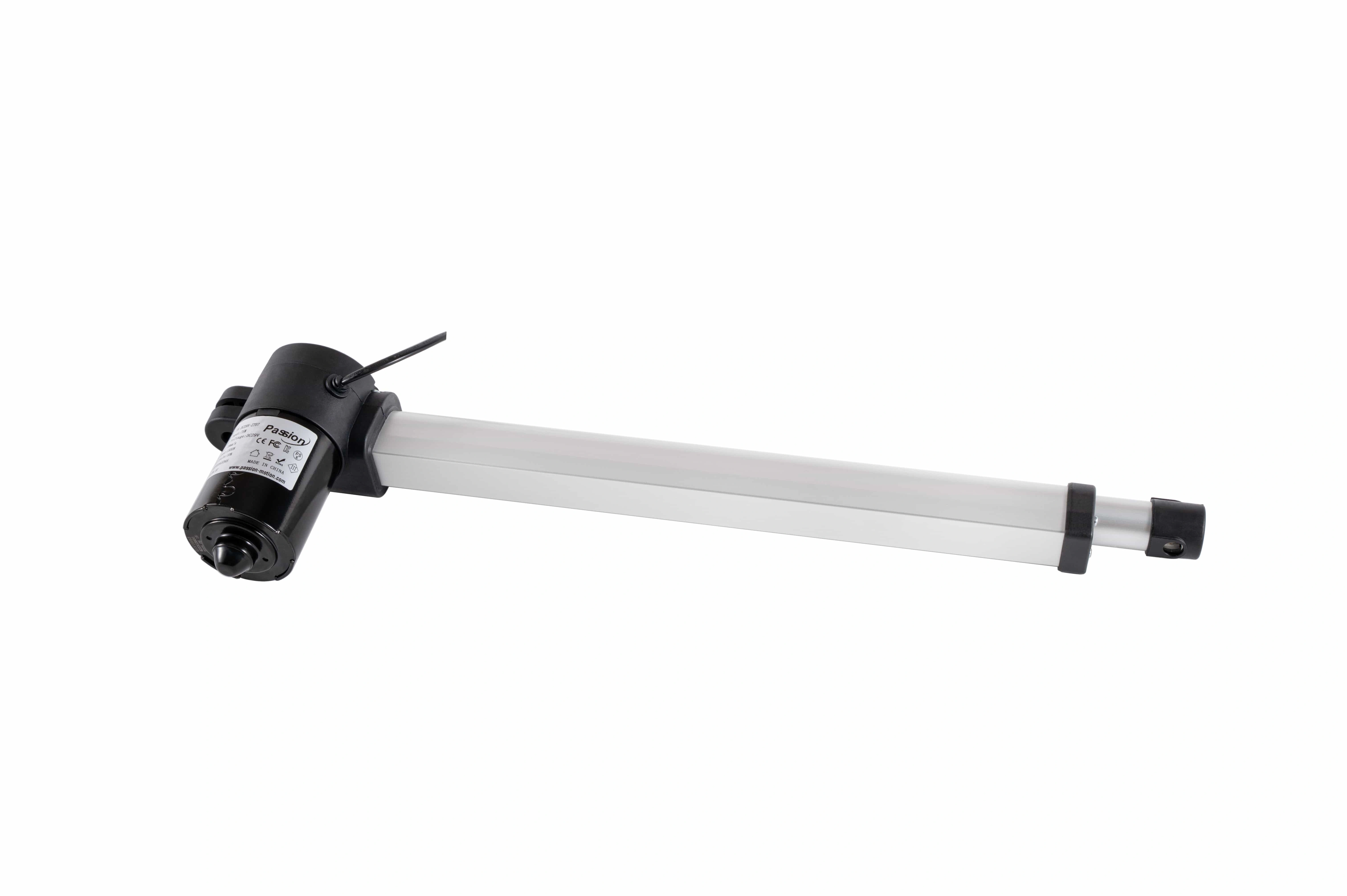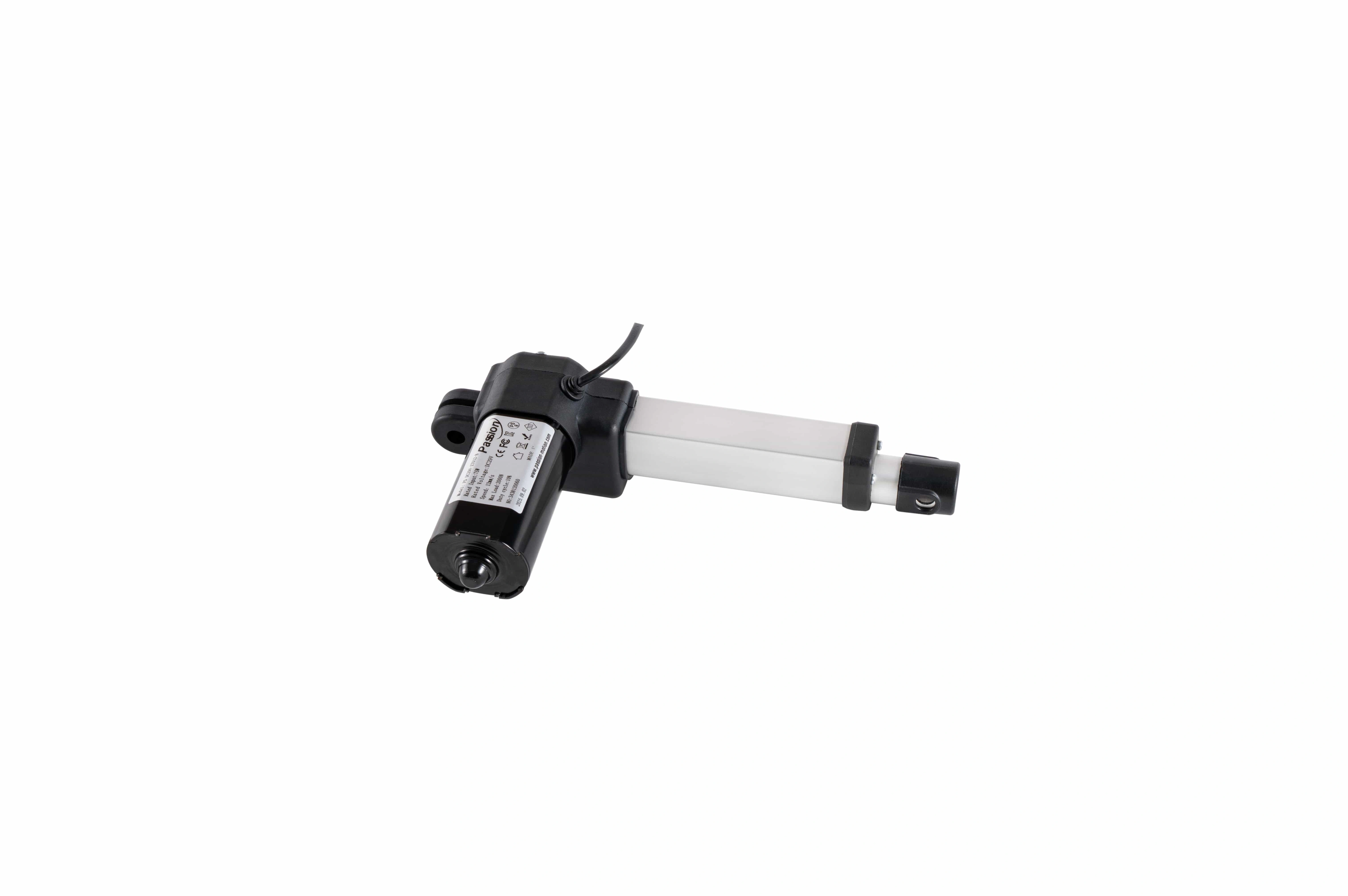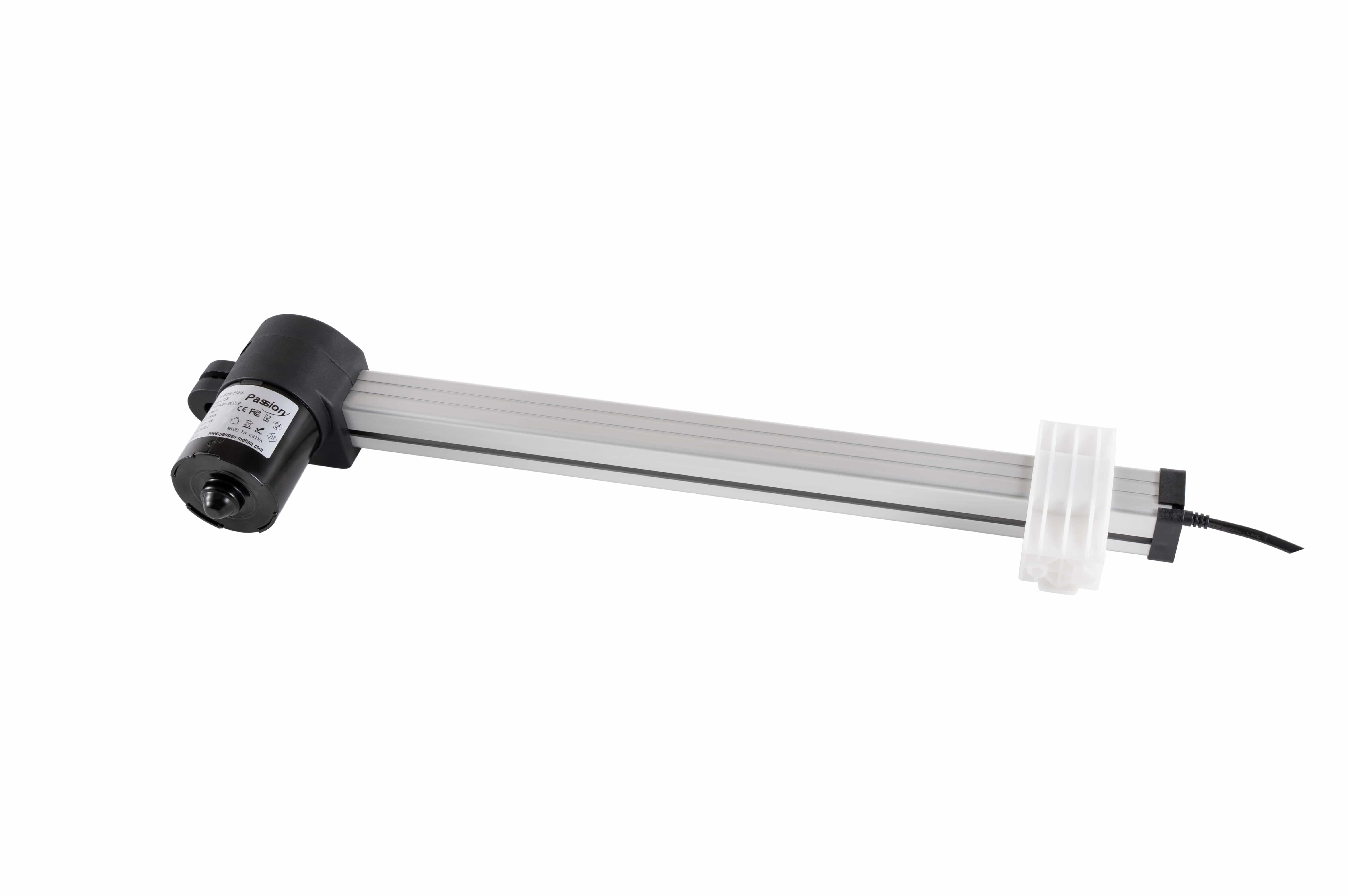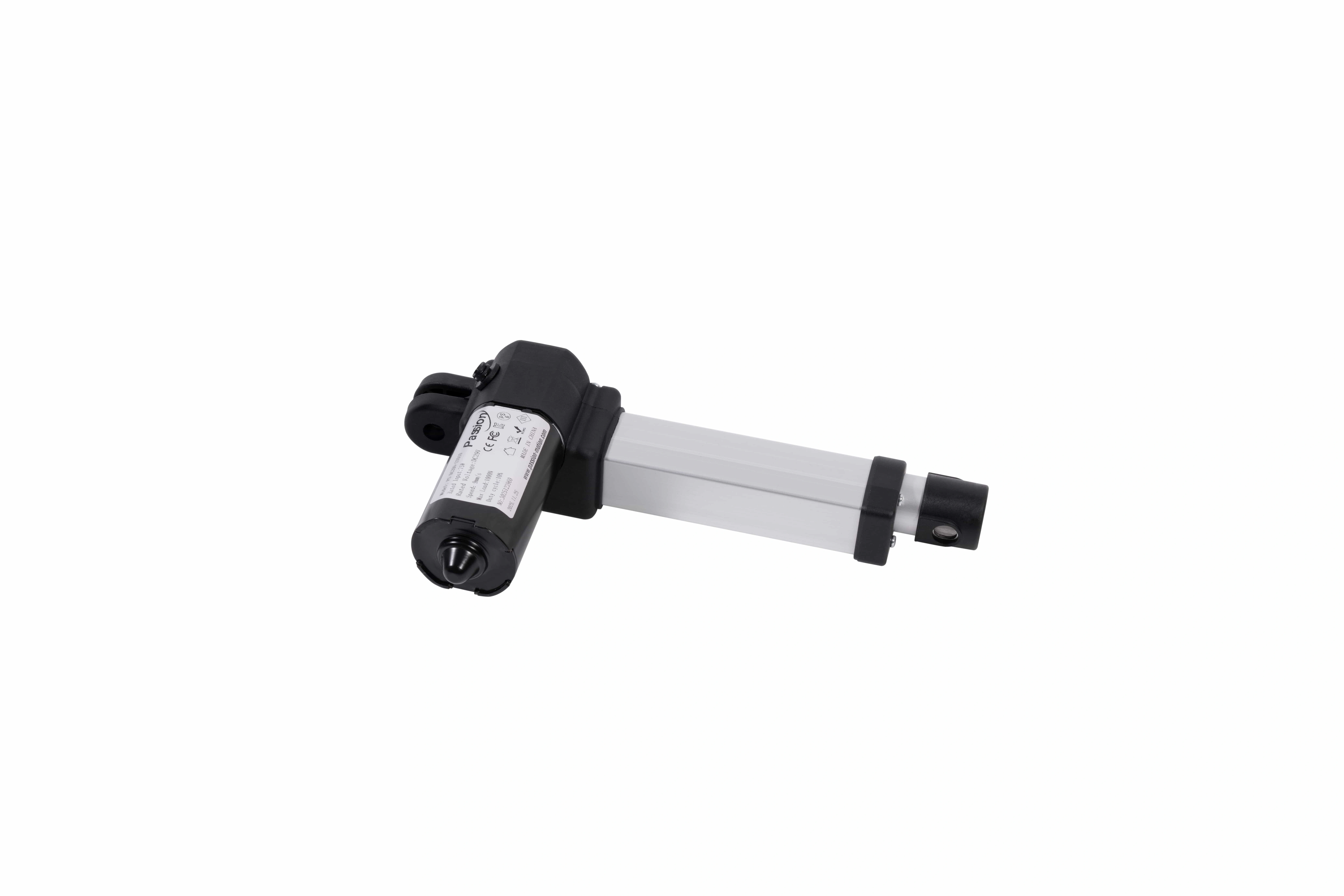

PT06 Linear Actuator: 3000N, 1000mm Stroke
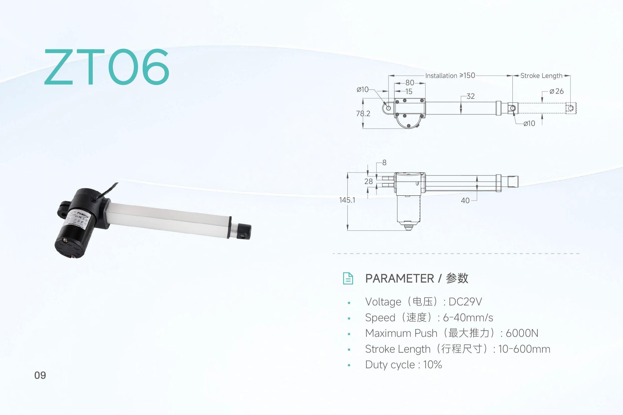
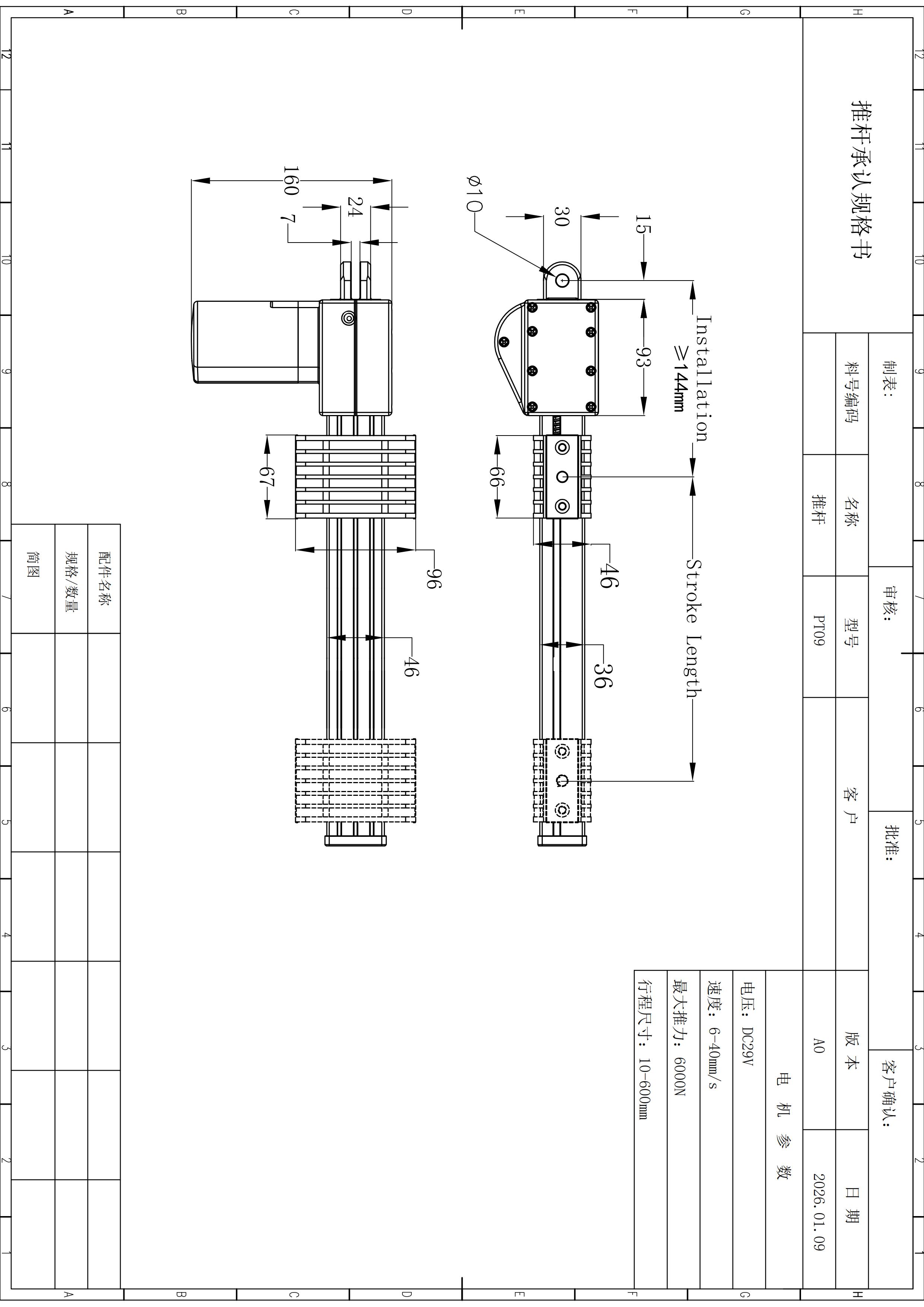
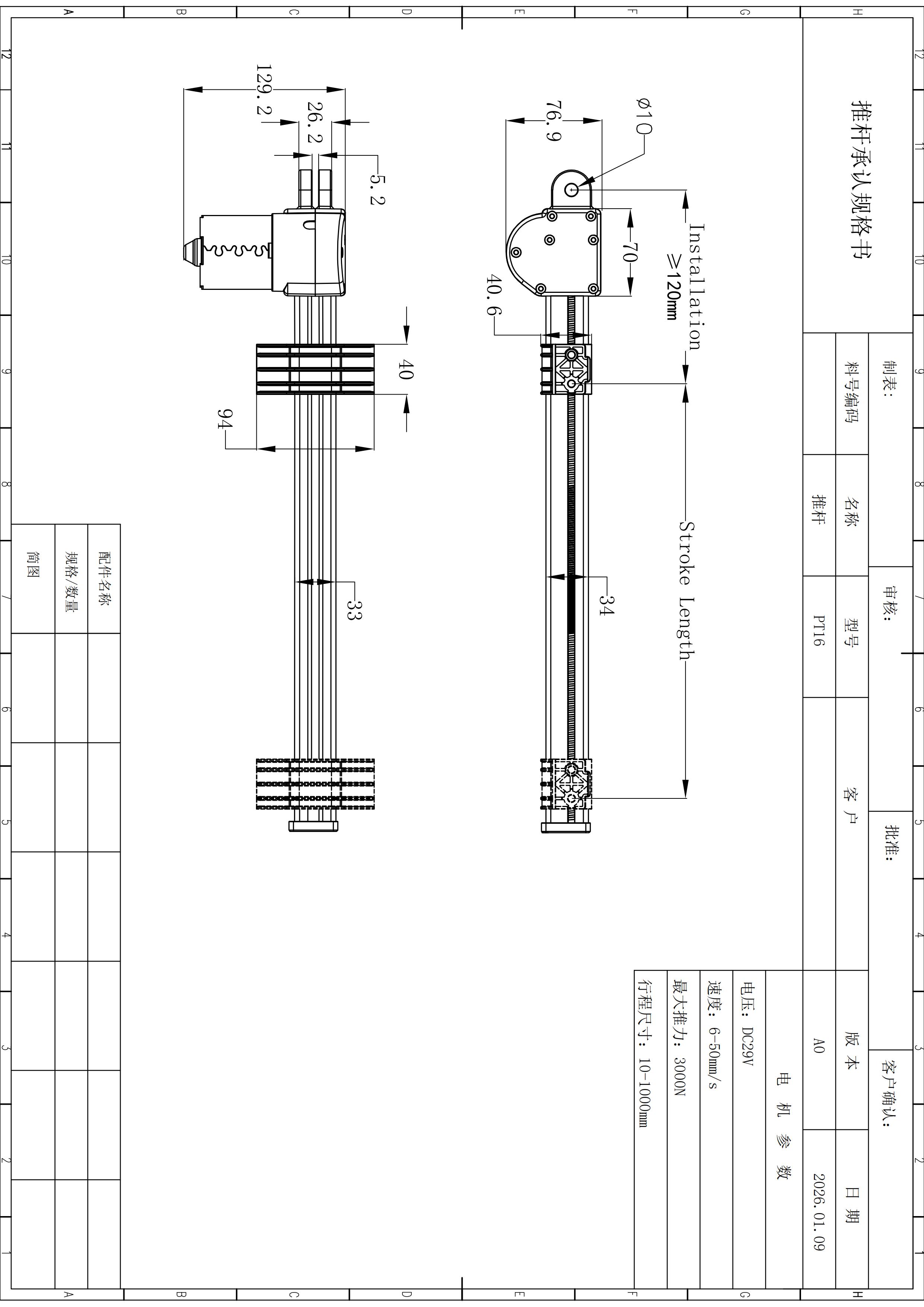
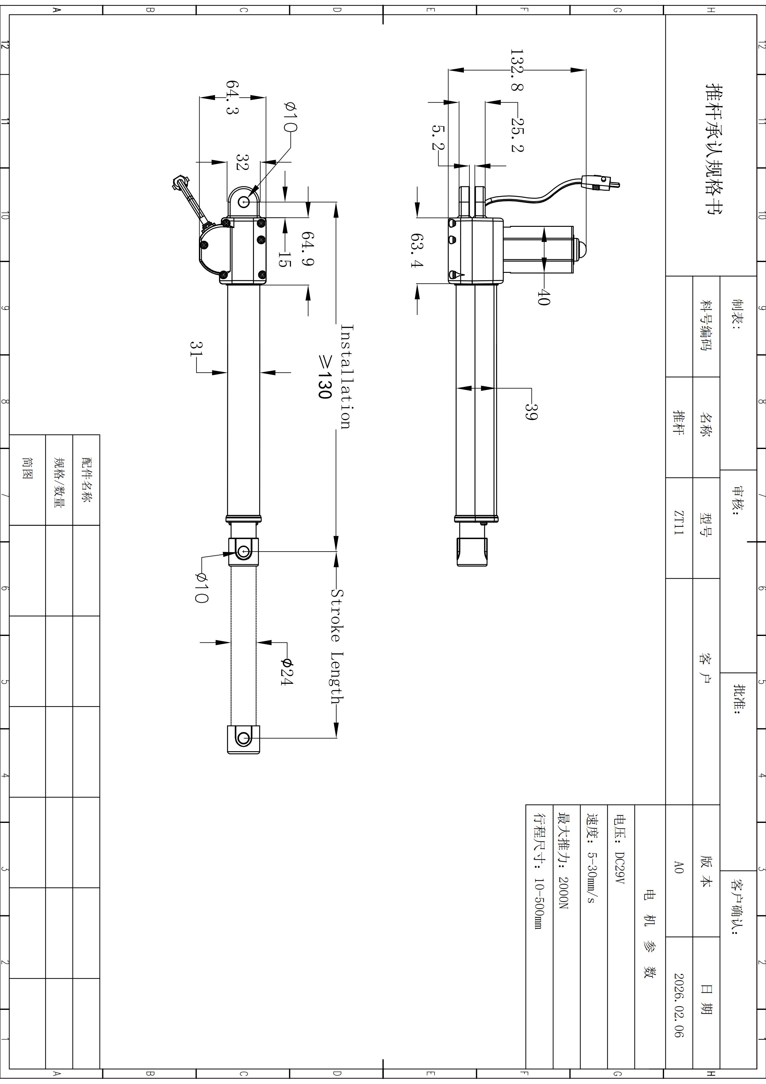
Review PT06 slider specifications including DC 29V, up to 3000N push, 6–40 mm/s speed, 10–1000 mm stroke, duty cycle and mounting dimensions.
PT06 Linear Actuator
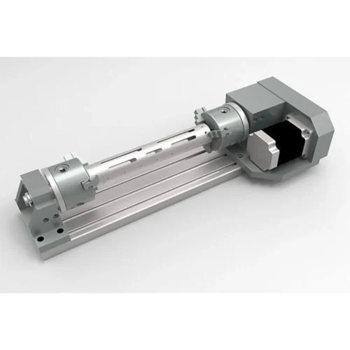
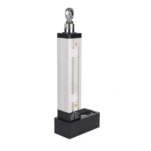
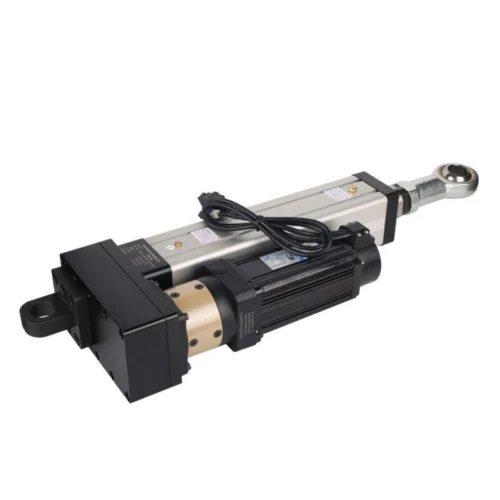
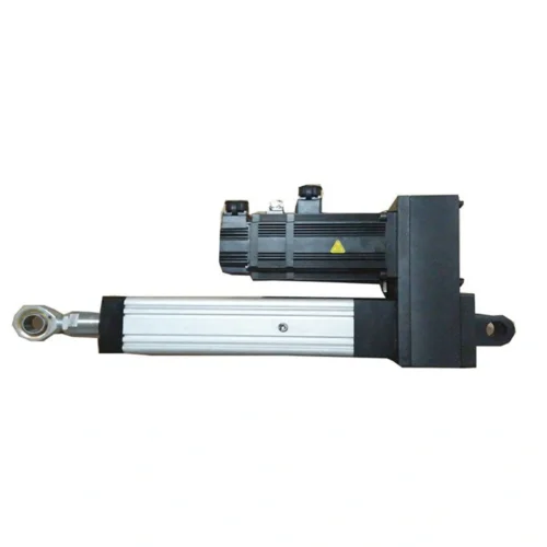
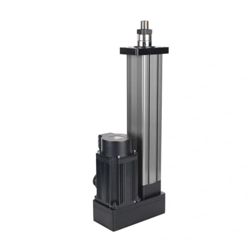
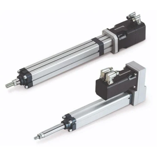
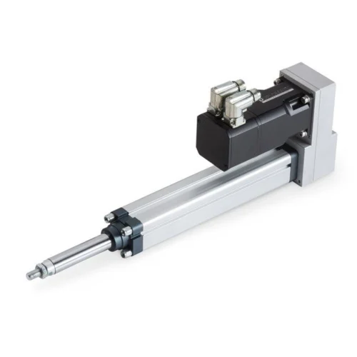
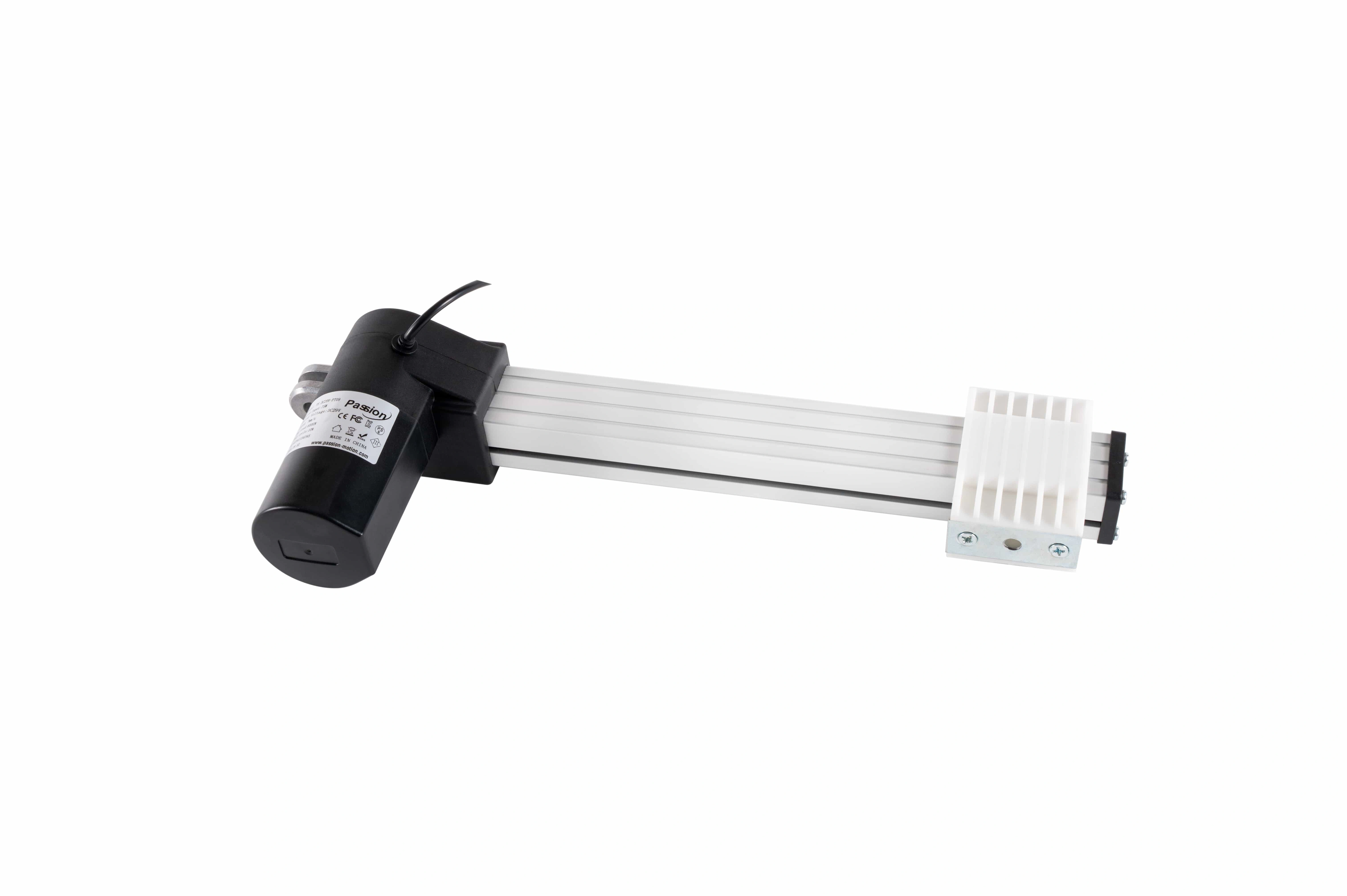
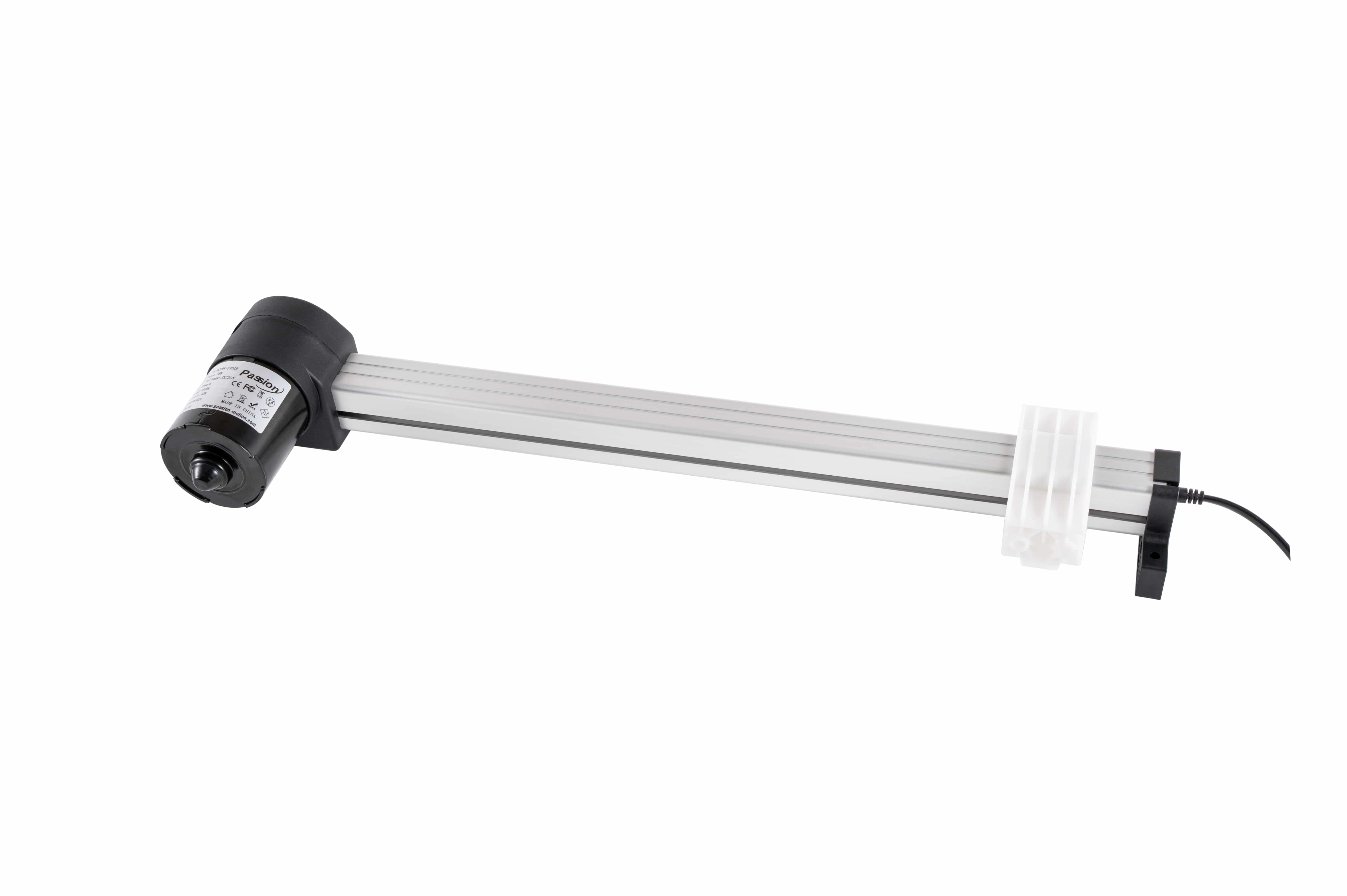
A DC 29V slider-style unit built around a moving carriage and fixed-track arrangement. Published limits reach 3,000 N push, 6–40 mm/s and 10–1,000 mm stroke; final selection still depends on the real loaded operating point and installation geometry.
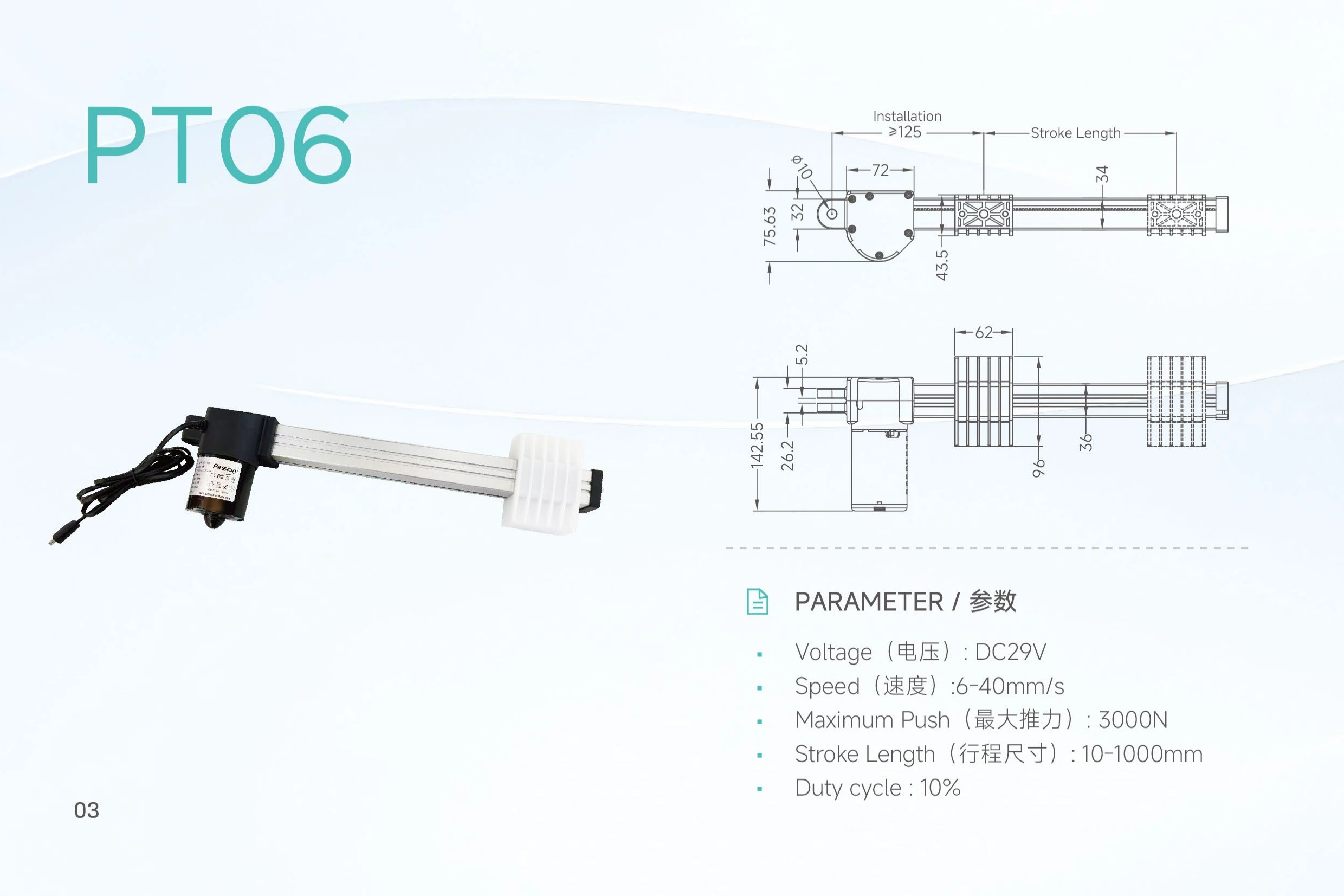 Fixed track / moving carriage
Separate maximum values from a verified force-speed operating point.
The local record does not include a PT06 force-speed curve, loaded-speed table, current-load curve, current draw, pull-force rating or static-hold value.
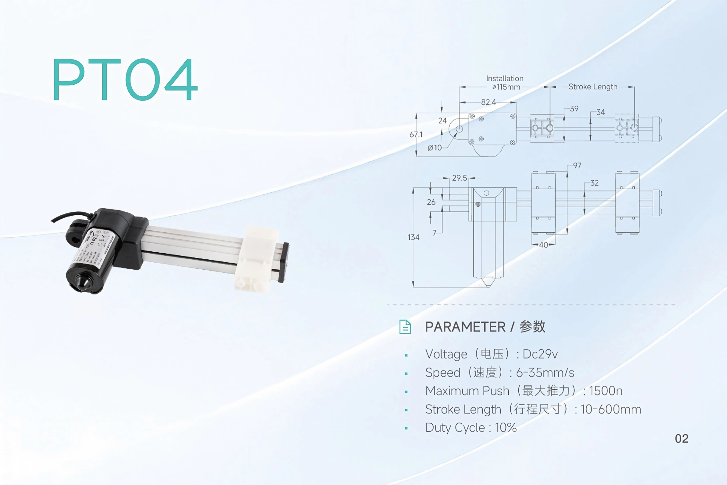
| Parameter | Published PT06 value | Selection note |
|---|---|---|
| Model | PT06 | Confirm the exact model on the project request |
| Input voltage | DC 29V | Confirm the available power architecture |
| Maximum push force | 3,000 N | Do not assume it coincides with maximum speed |
| Speed | 6–40 mm/s | Loaded-speed confirmation is required |
| Stroke | 10–1,000 mm | Select travel from the real mechanism requirement |
| Duty cycle | 10% | The local record does not state the test basis |
Inspect the slider architecture one constraint at a time.
A slider actuator changes the packaging question: fixed track, moving carriage, alignment and service access all occupy different parts of the installation problem. Select a focus below to change the engineering check.
Reserve the fixed track envelope
Start with the surface that stays fixed. Confirm the track footprint, mounting interface and surrounding structure before treating stroke as usable travel.
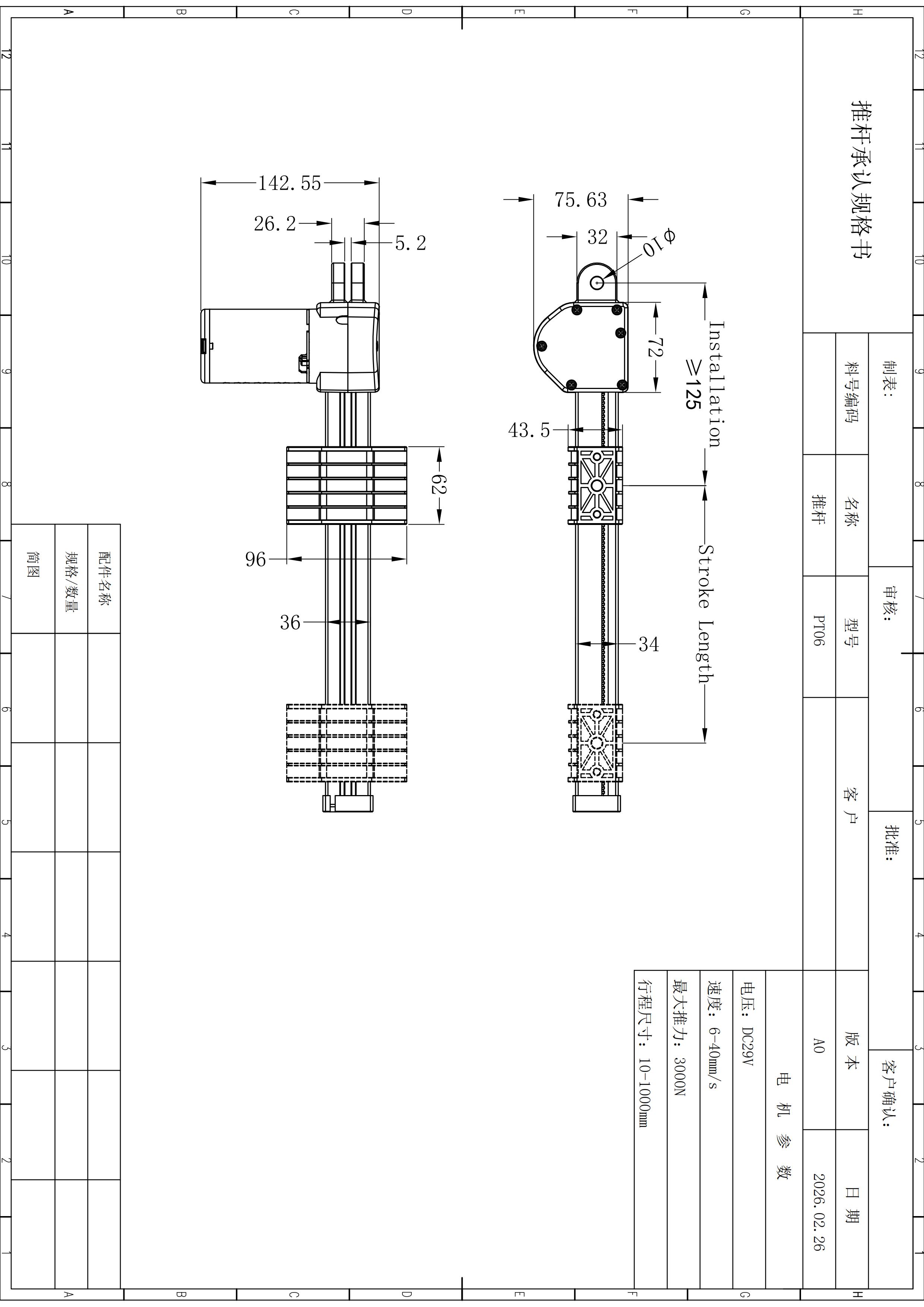
Carry the operating point into controls, wiring and release evidence.
PT06 selection should remain traceable from load and travel through mounting geometry, electrical architecture and final technical documentation.
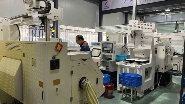
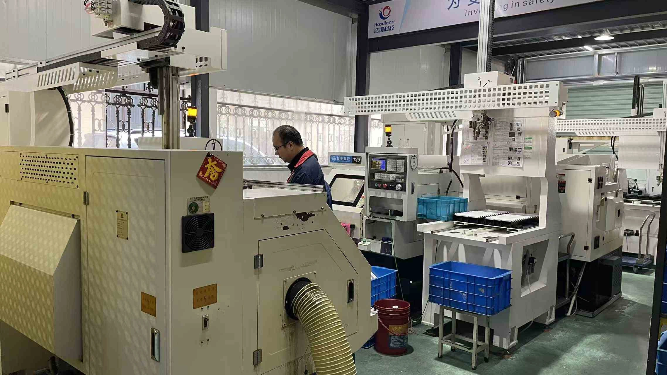 Production environment / first-party factory image
Factory imagery should be inspectable—not decorative wallpaper.
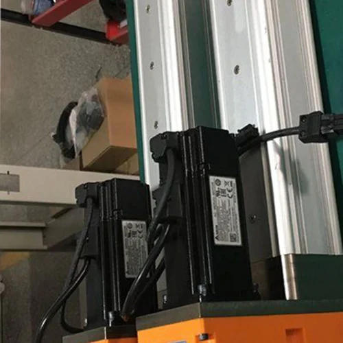
This first-party image provides manufacturing context for the ServoCylMotion production environment. It is deliberately separated from PT06 specification claims so a visual does not become unsupported process evidence.
Continue when the slider architecture solves the motion path. Pause when missing data controls the design.
PT06 is a candidate when the mechanism can use DC 29V, needs push force within the published 3,000 N maximum, fits 10–1,000 mm stroke and benefits from a moving-carriage / fixed-track arrangement.
Use the page for screening—not as configuration approval.
The final project decision still depends on the real operating point, geometry and interfaces.
What is the maximum push force of PT06?
The local record lists 3,000 N maximum push. It does not prove every listed speed or stroke can operate at that force.
What speed range is published?
6–40 mm/s. Provide the working load if the design needs a specific loaded speed.
What stroke range is listed?
10–1,000 mm. Check selected stroke against the complete slider envelope and full-travel clearance.
Can 3,000 N and 40 mm/s be assumed at the same time?
No. The evidence package does not contain a PT06 force-speed curve proving that operating point.
What voltage does PT06 use?
PT06 is listed as DC 29V. Current requirement, switching method and control pairing still need configuration-level review.
What does the 10% duty cycle mean?
The local record states 10% but does not provide the exact test basis or run/rest timing.
Are the listed dimensions ready for machining?
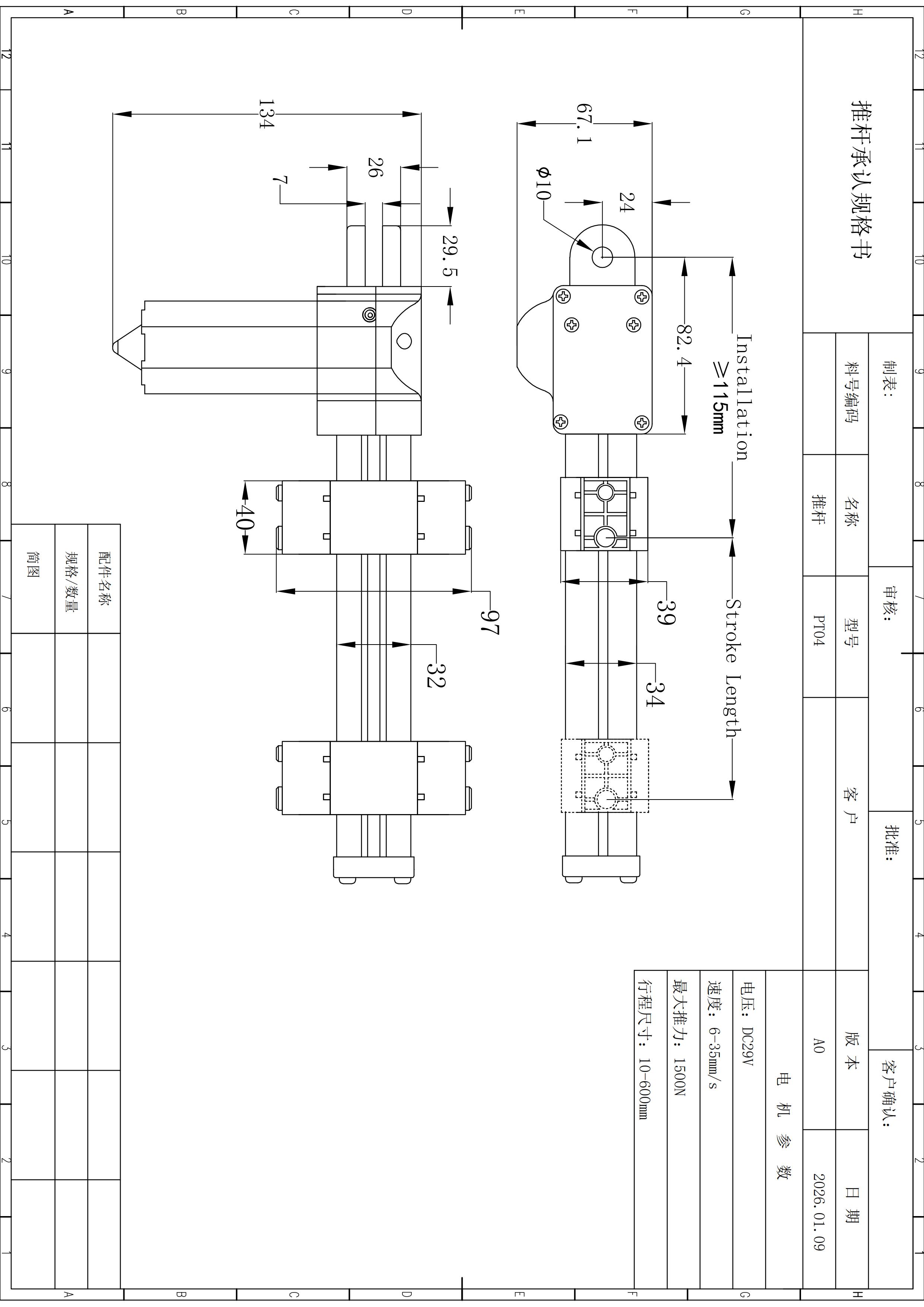
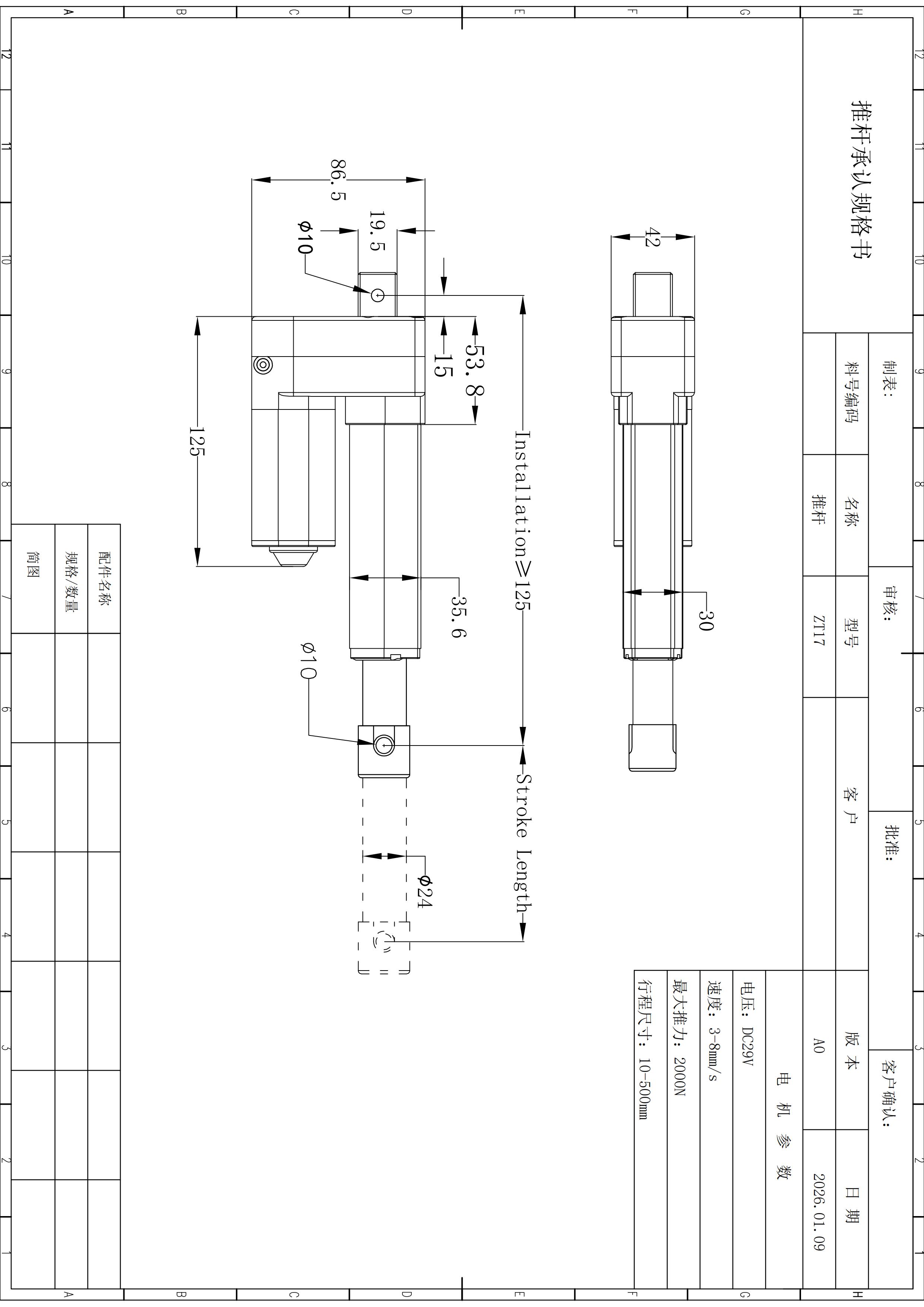
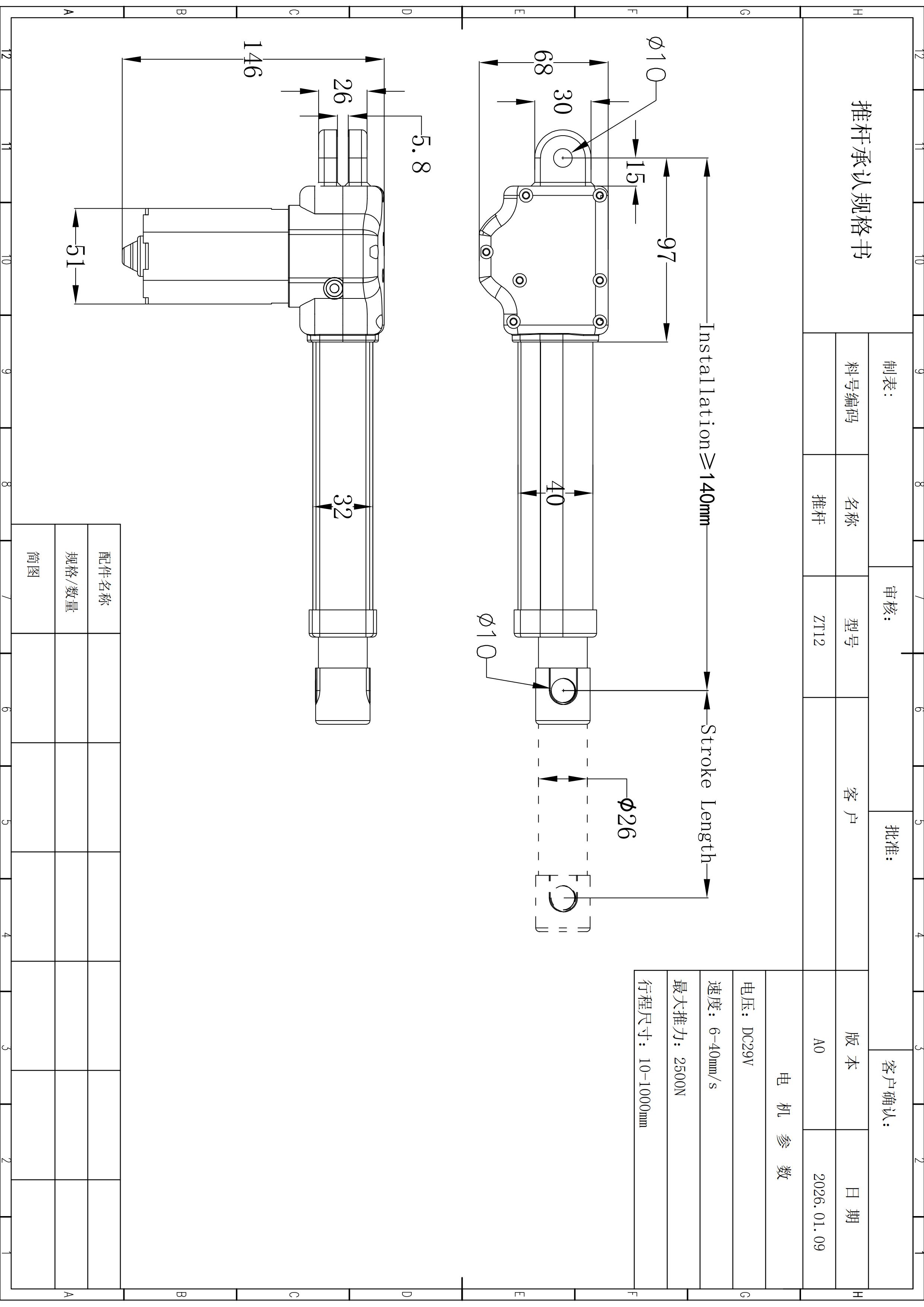
No. They are preliminary references. Confirm the current released drawing before fixing tolerances, brackets or hole locations.
Does PT06 include a specific feedback or controller interface?
The evidence package used for this page does not define one. State the required control and feedback method in the inquiry.
Define the carriage path, working load and loaded speed before release.
Send working load, required loaded speed, stroke, available installation space, cycle, environment, control and feedback needs, quantity and required documents.
Request PT06 review →