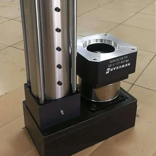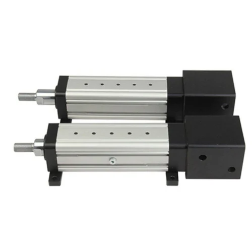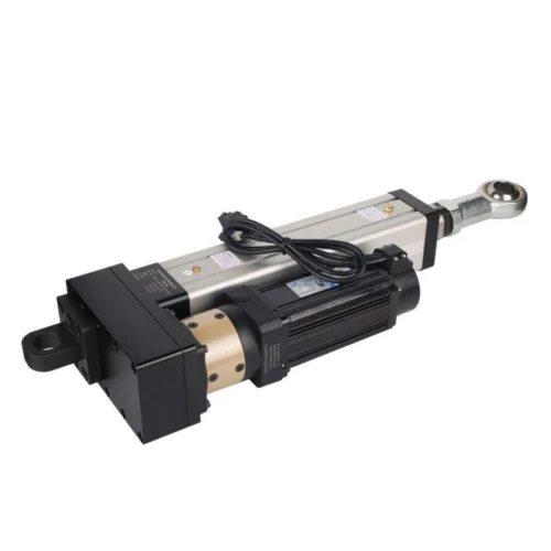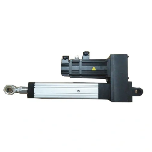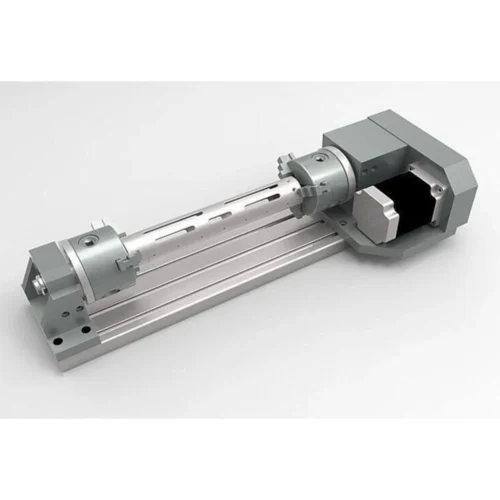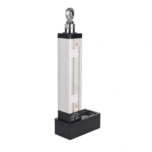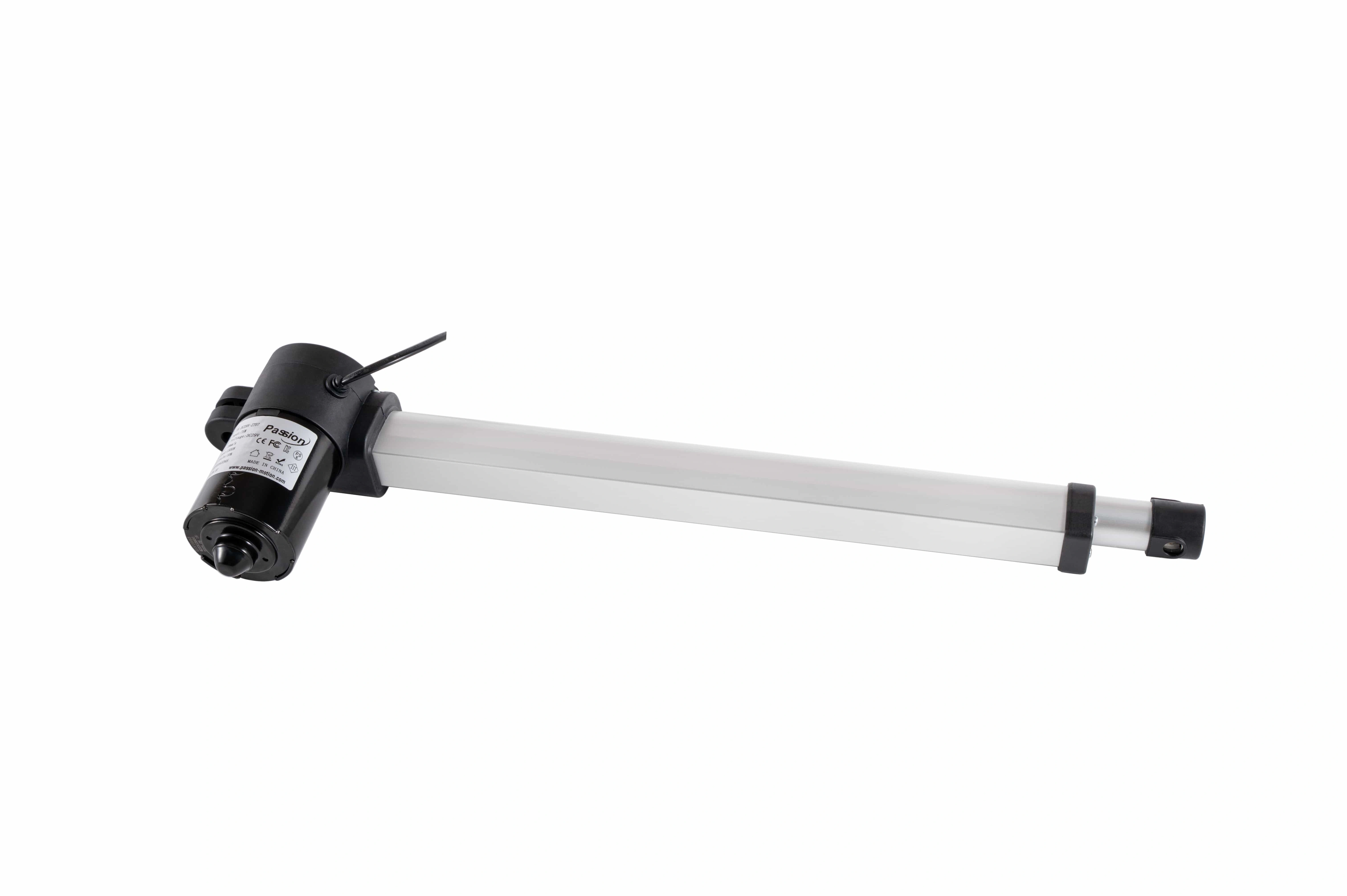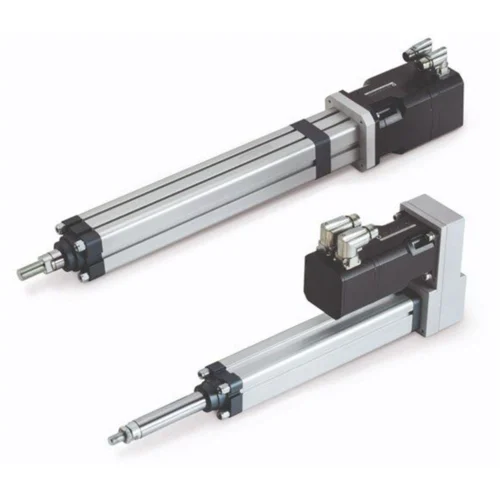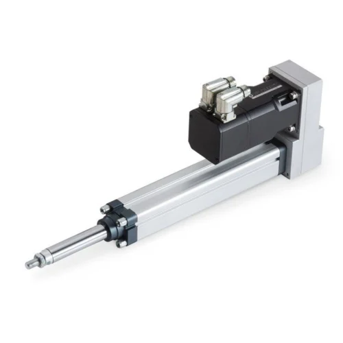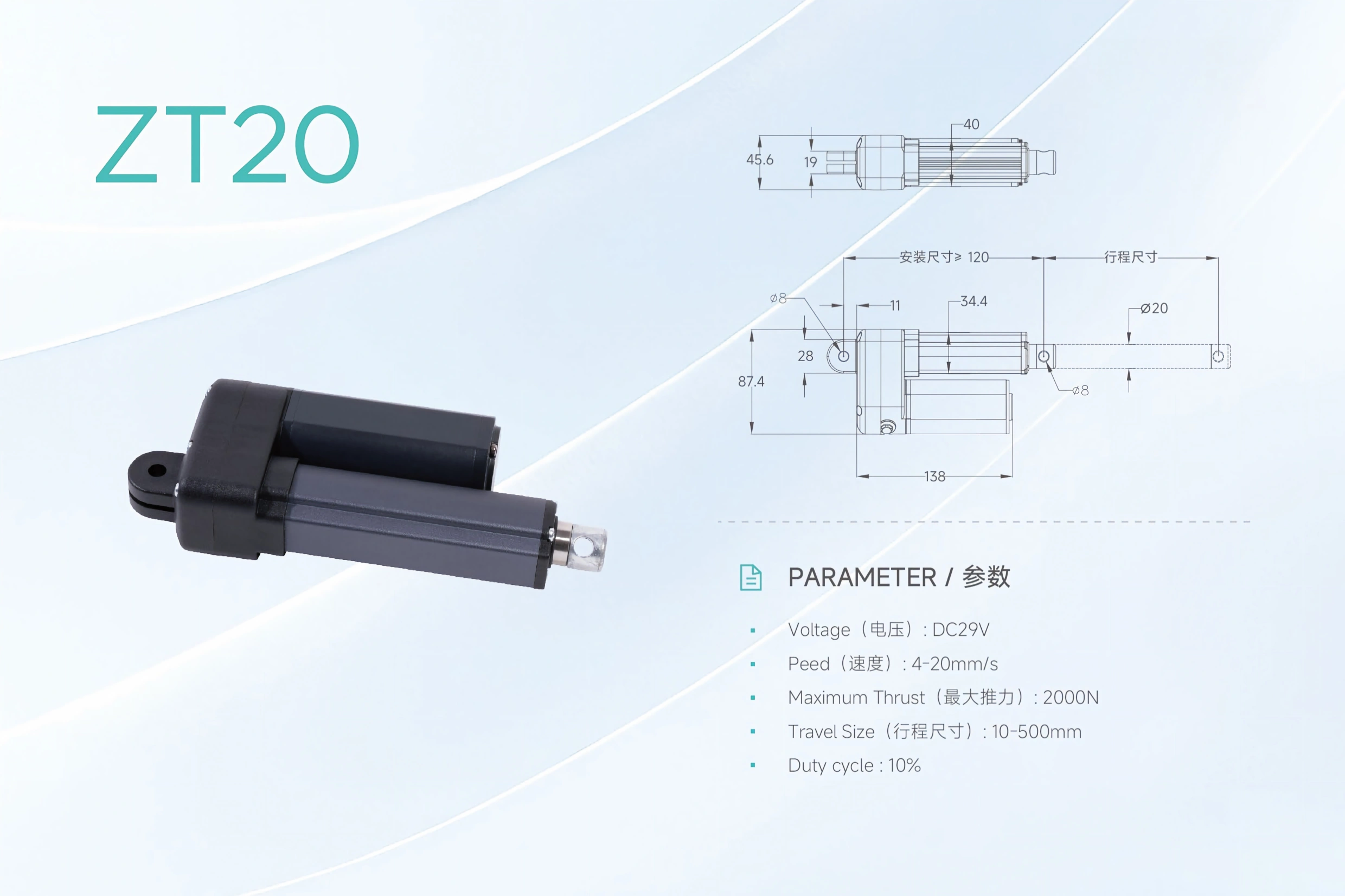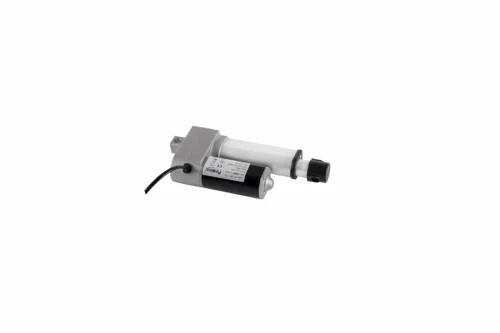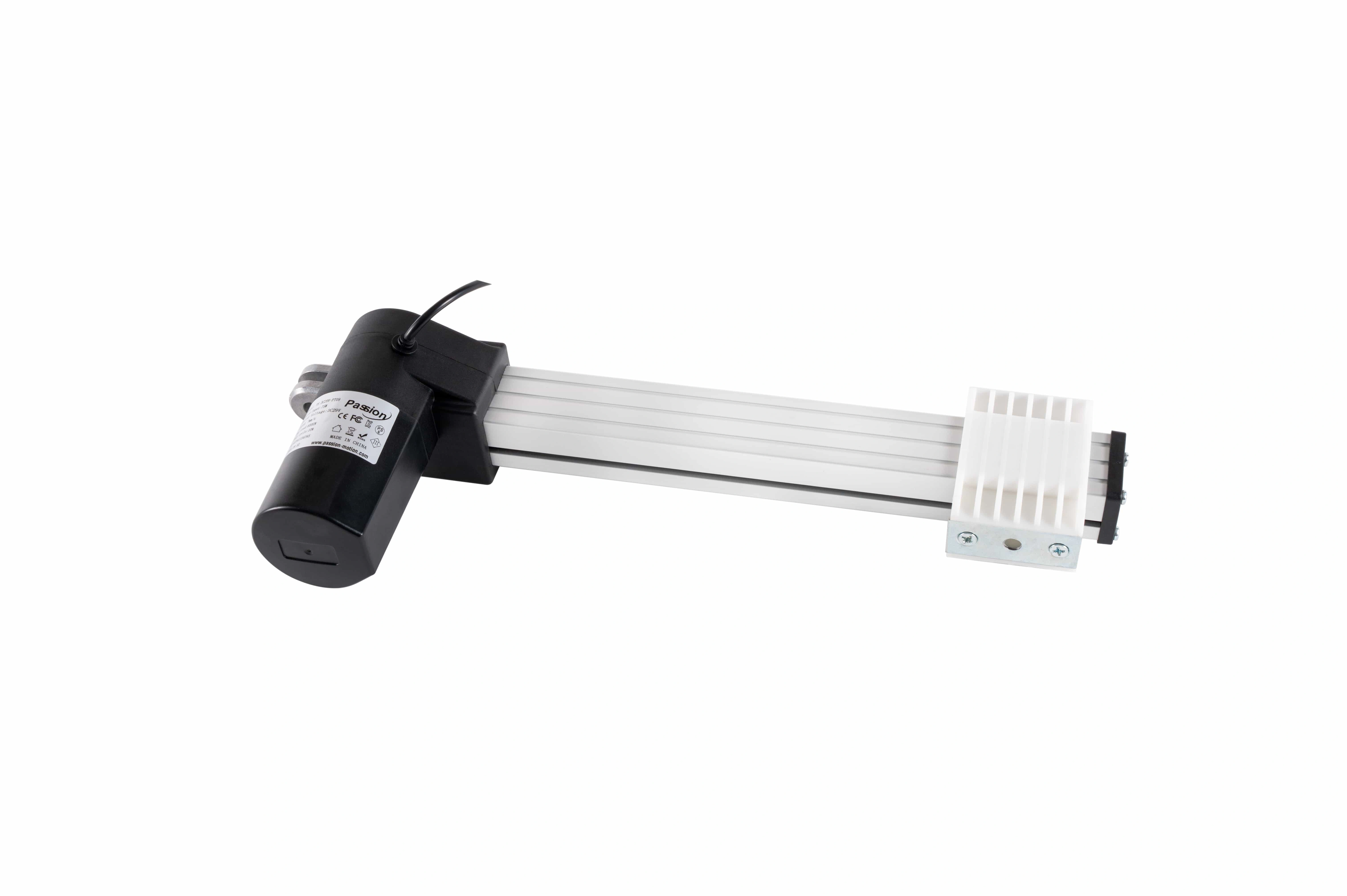

PT18 Linear Actuator: 3000N, 50mm/s, 1000mm Stroke
Review PT18 specifications for DC 29V operation, up to 3000N push force, 6–50mm/s speed, 10–1000mm stroke, duty cycle and mounting dimensions.
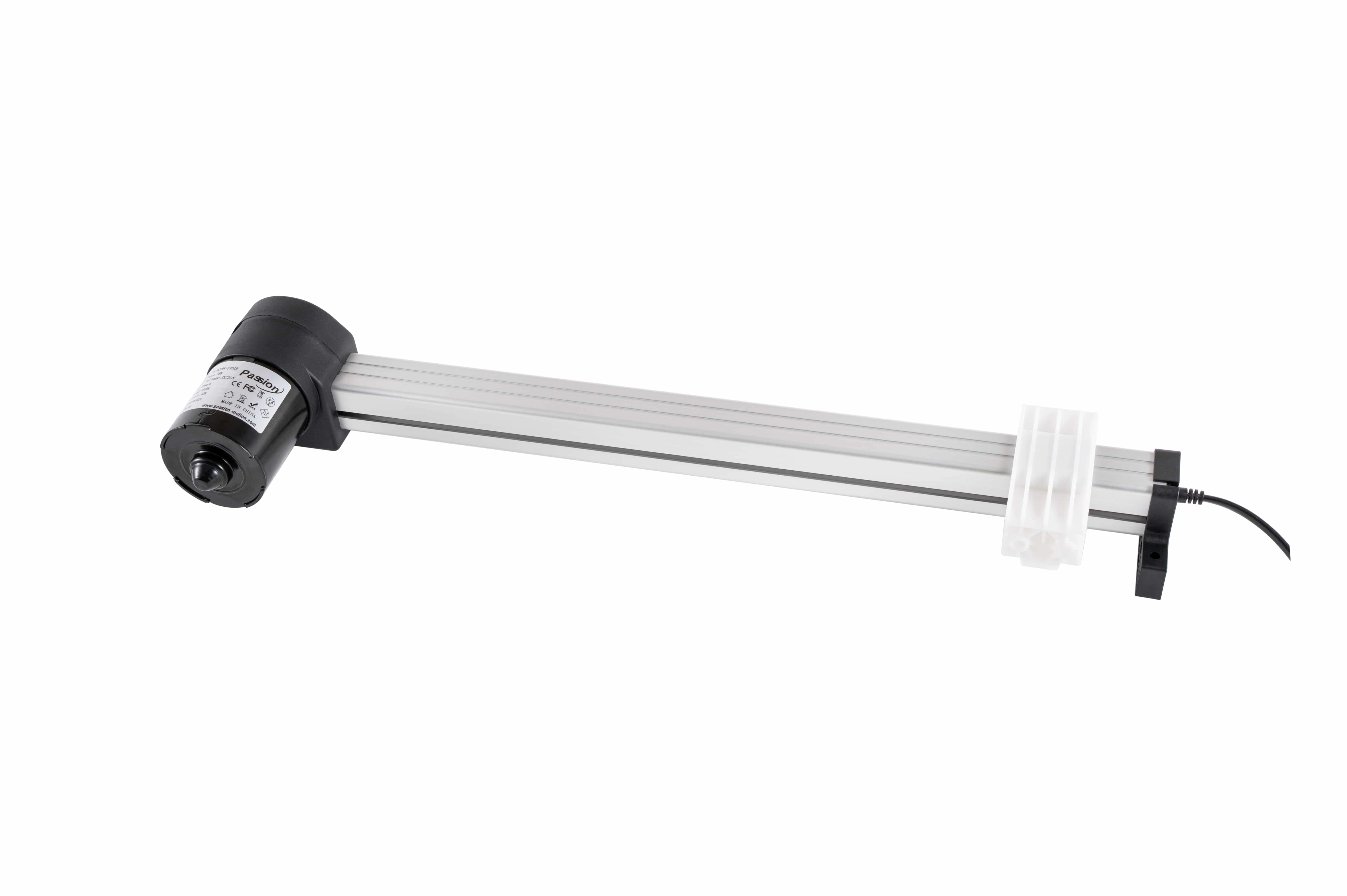
PT18 Linear Actuator
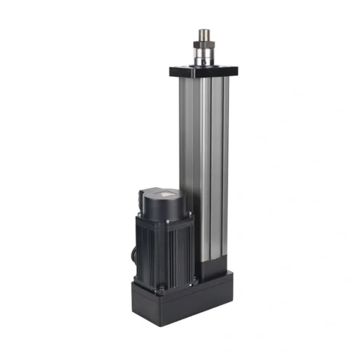
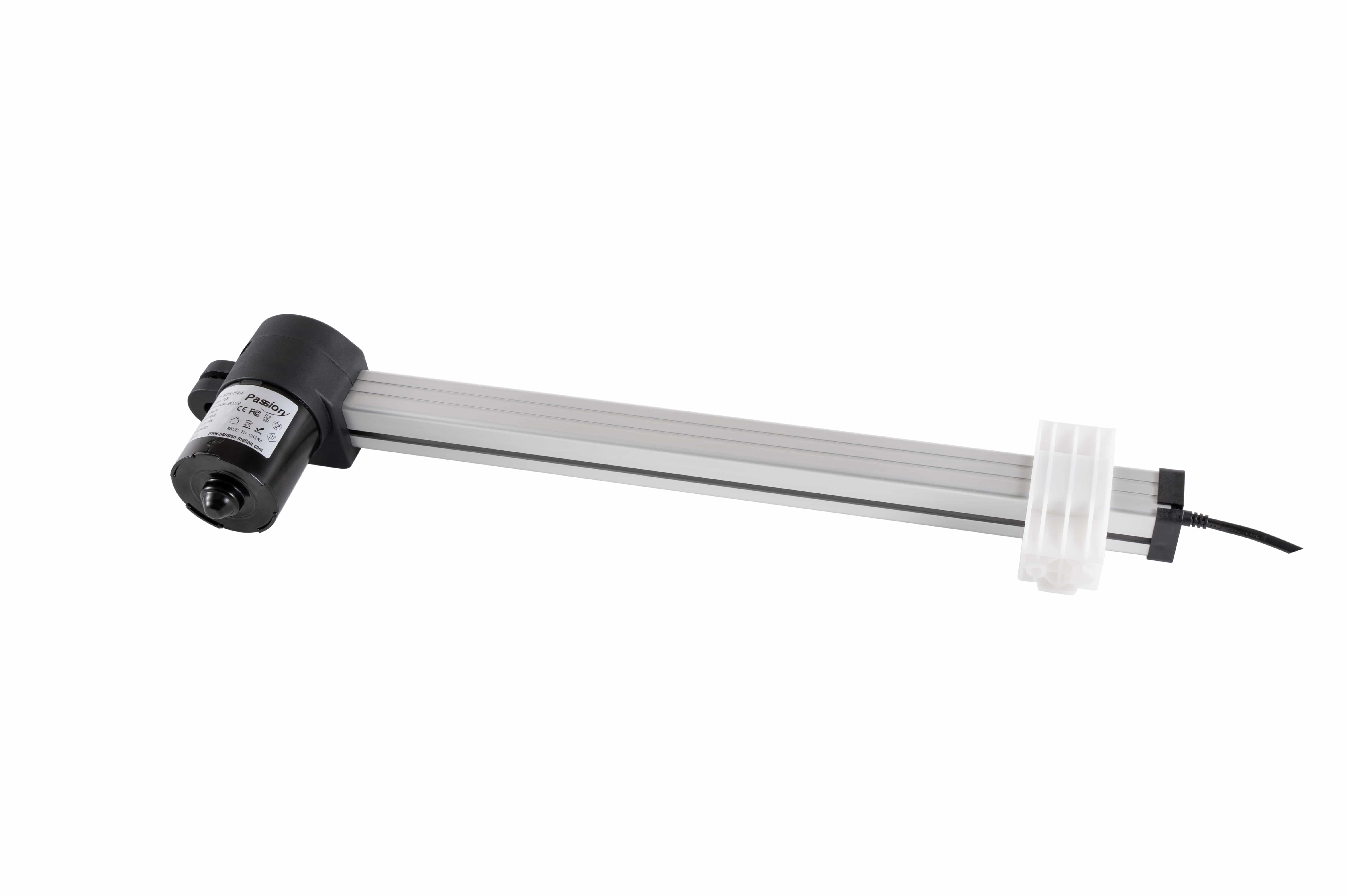
A slider-style motion unit for projects that need long guided travel while the drive body stays fixed. Published range: DC 29V, up to 3,000 N push, 6–50 mm/s speed and 10–1000 mm stroke.
Change the review state and watch the motion window become the design question.
These states do not create new performance data. They direct attention to retracted fit, selected travel and the support / clearance envelope.
Start with the retracted installation offset.
Fit the fixed body and mounting end before allocating the selected travel and carriage clearance.
The long-travel story hands its active question into the evidence table.
Switch the envelope state above and matching rows receive focus without hiding the full specification set.
| Parameter | Published PT18 value | Selection note |
|---|---|---|
| Operating voltage | DC 29V | Confirm the project power architecture before release. |
| Maximum push | Up to 3,000 N | Maximum value; loaded-speed conditions are not provided. |
| Speed | 6–50 mm/s | State the required speed under working load. |
| Stroke | 10–1000 mm | Select travel from the real motion requirement and installation space. |
| Duty cycle | 10% | Published percentage only; no time basis is stated in the local record. |
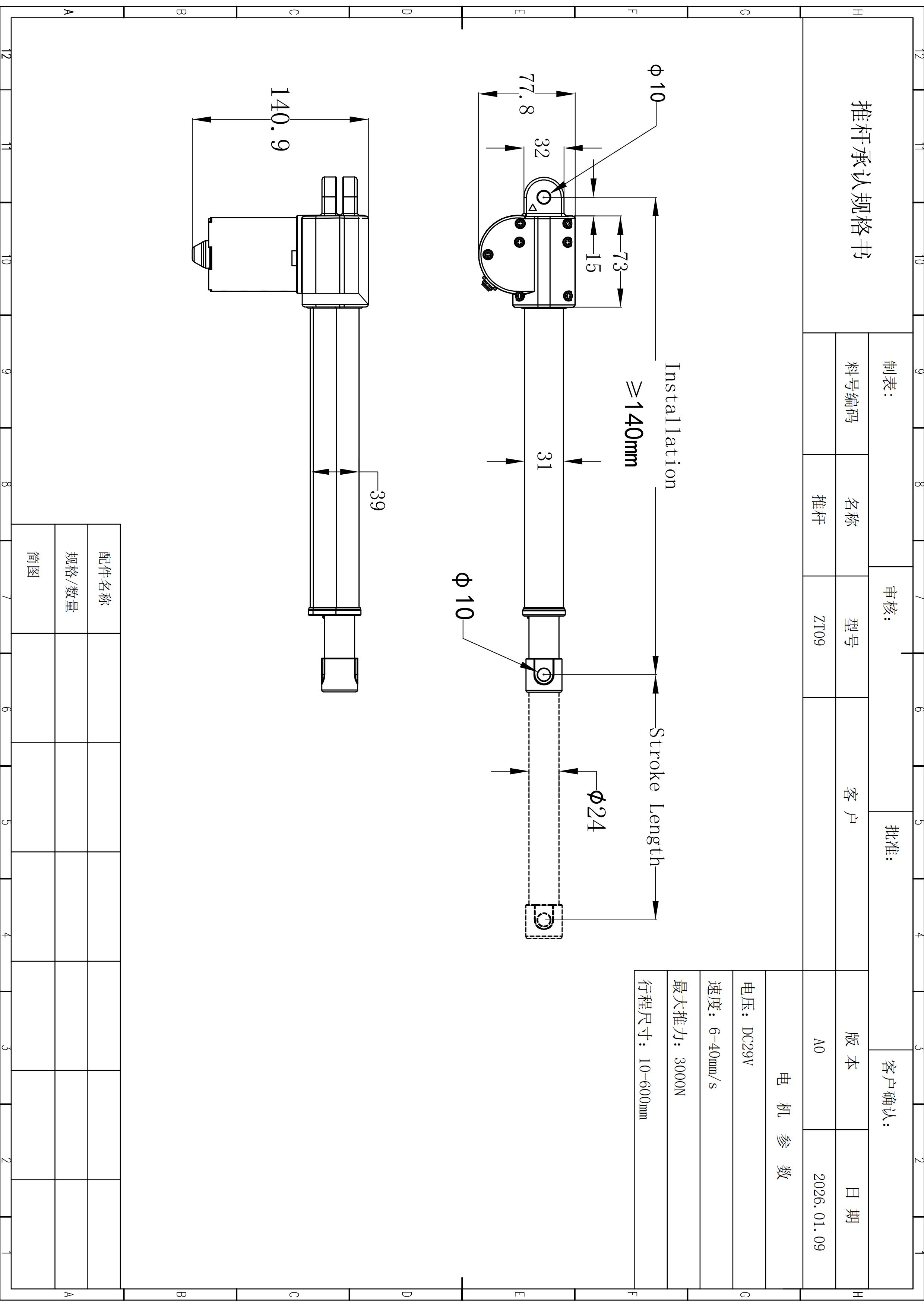
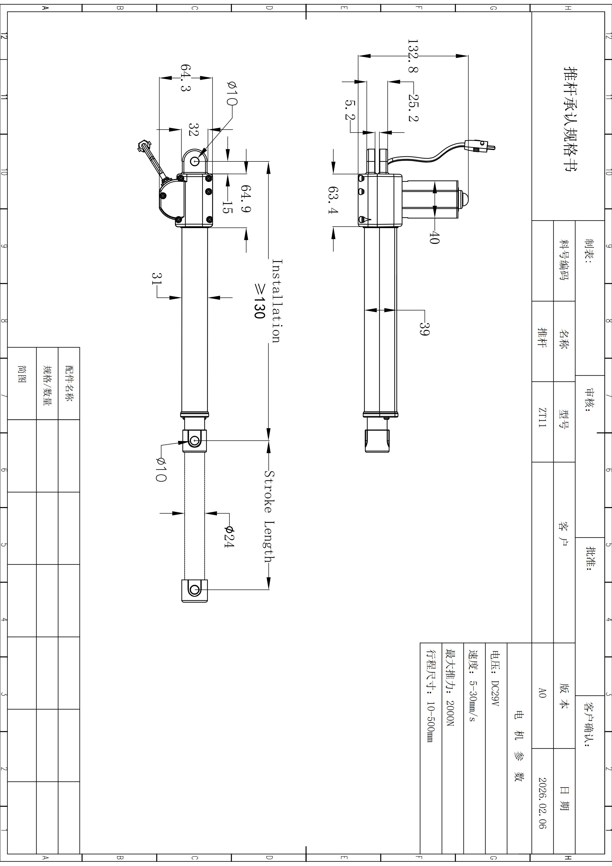
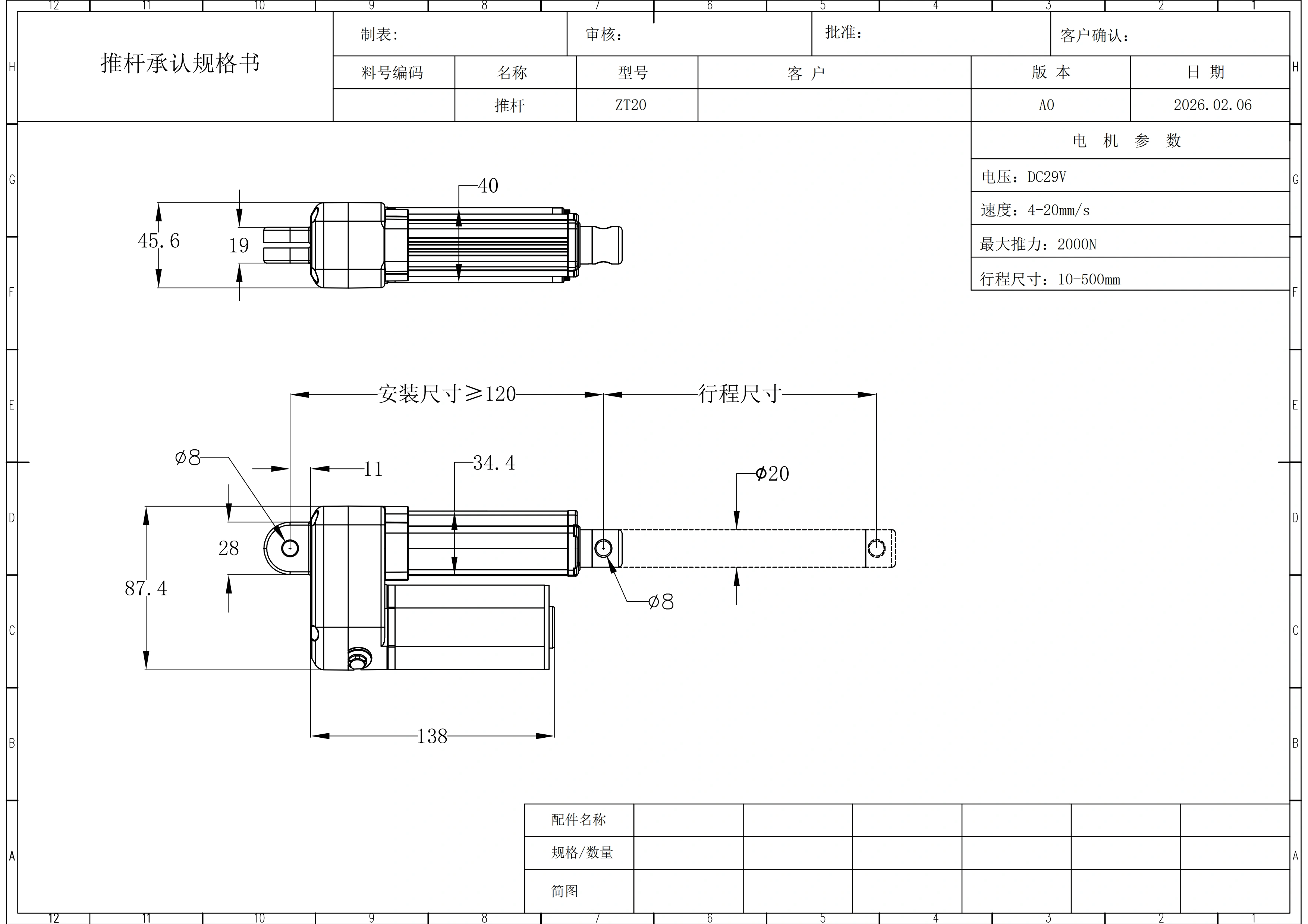
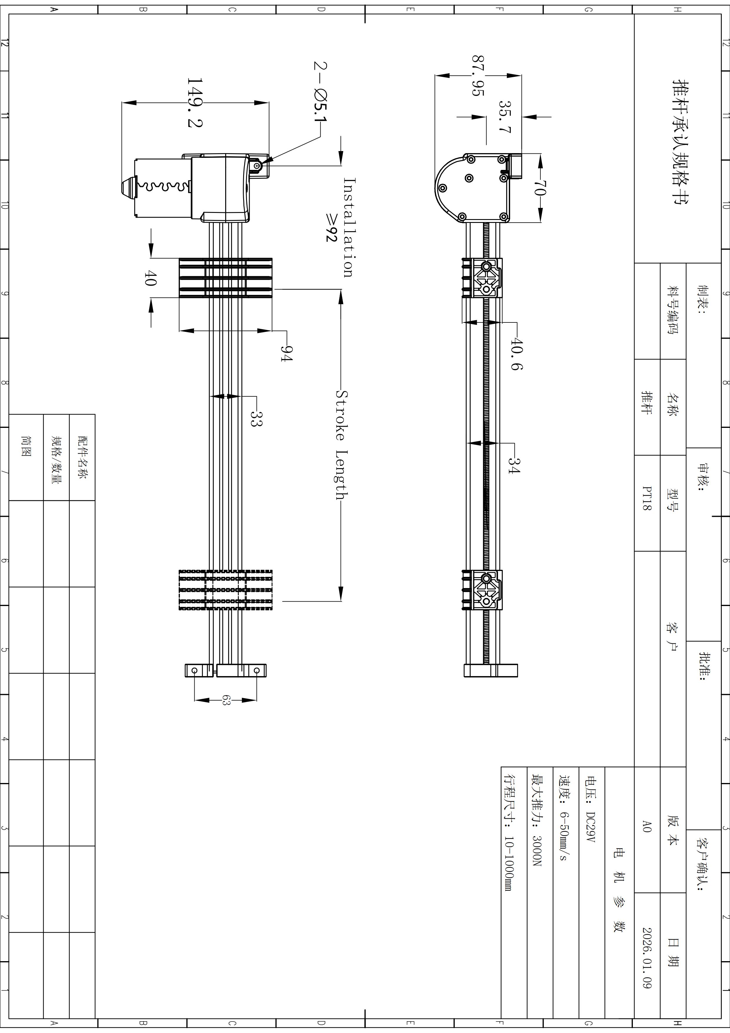
| Mounting holes | 2 × Ø5.1 mm | Check bracket geometry and fastener arrangement. |
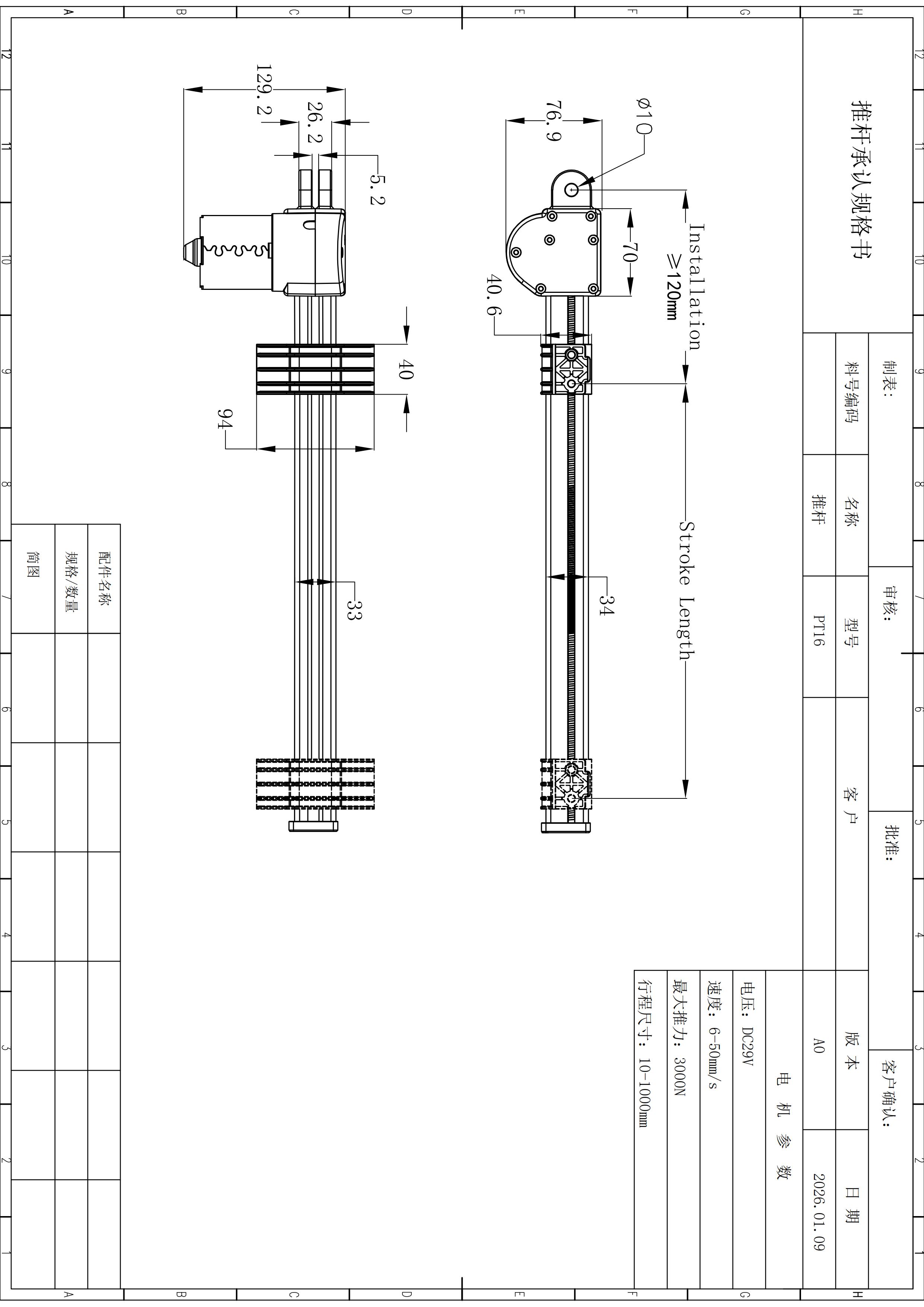
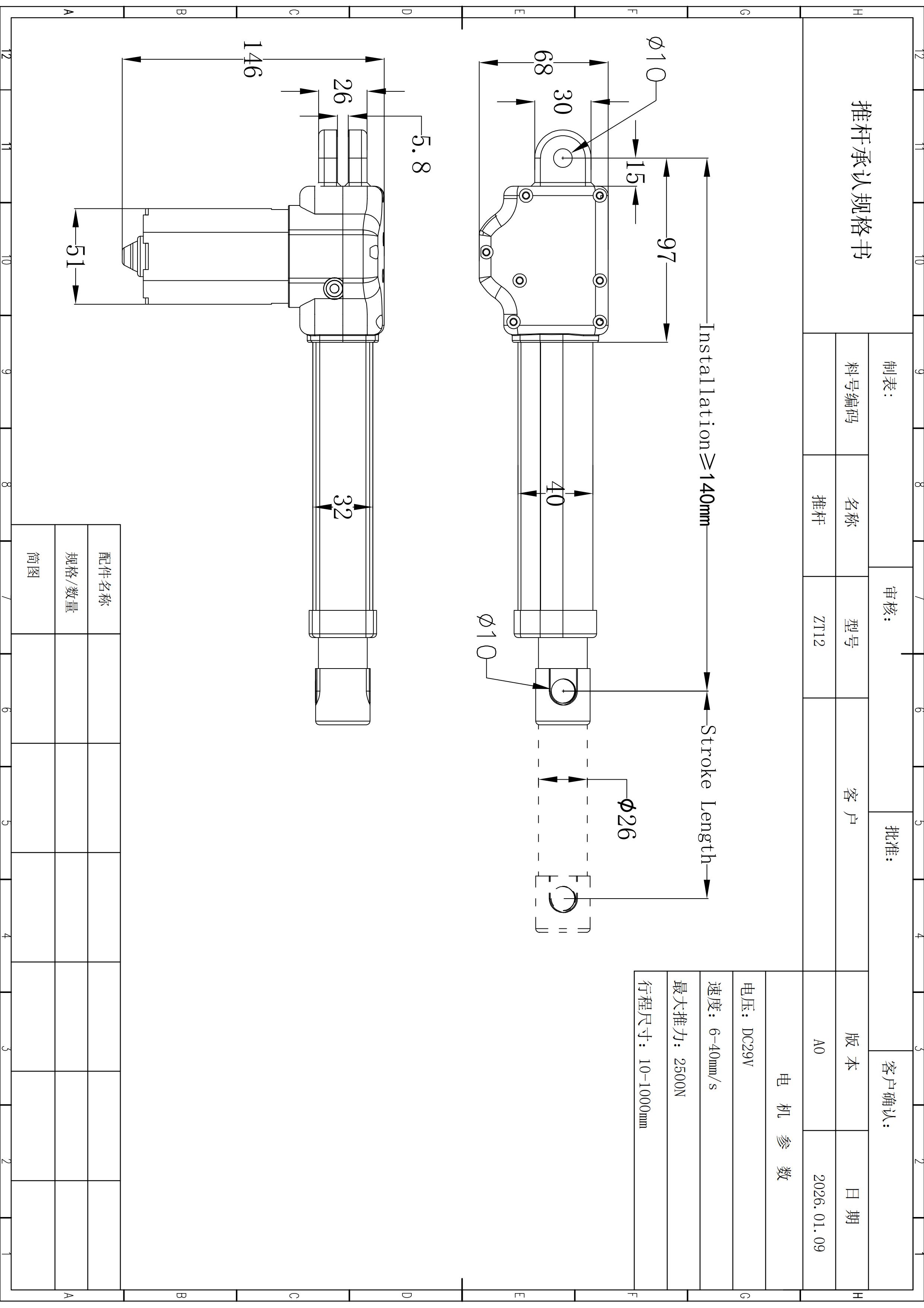
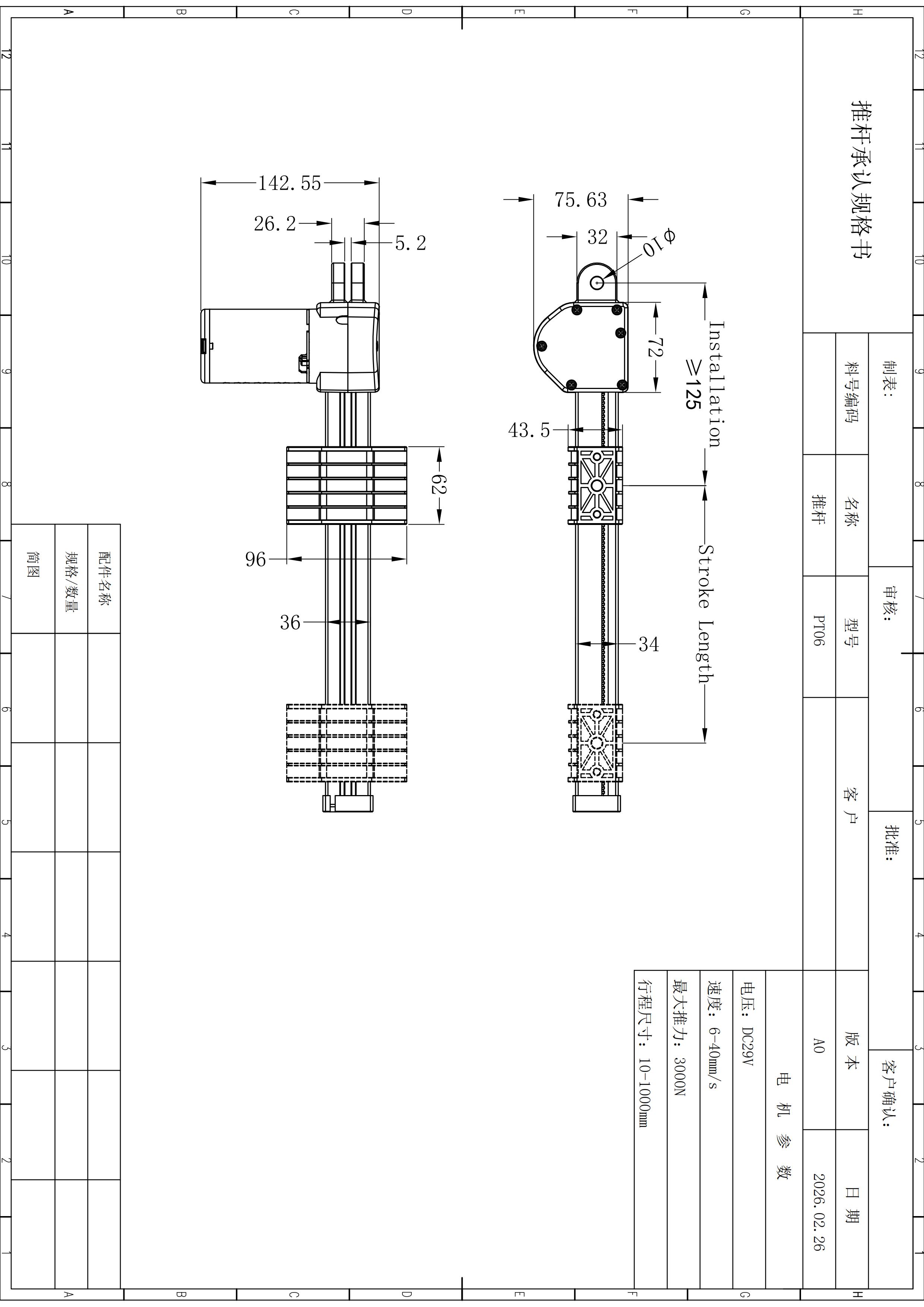
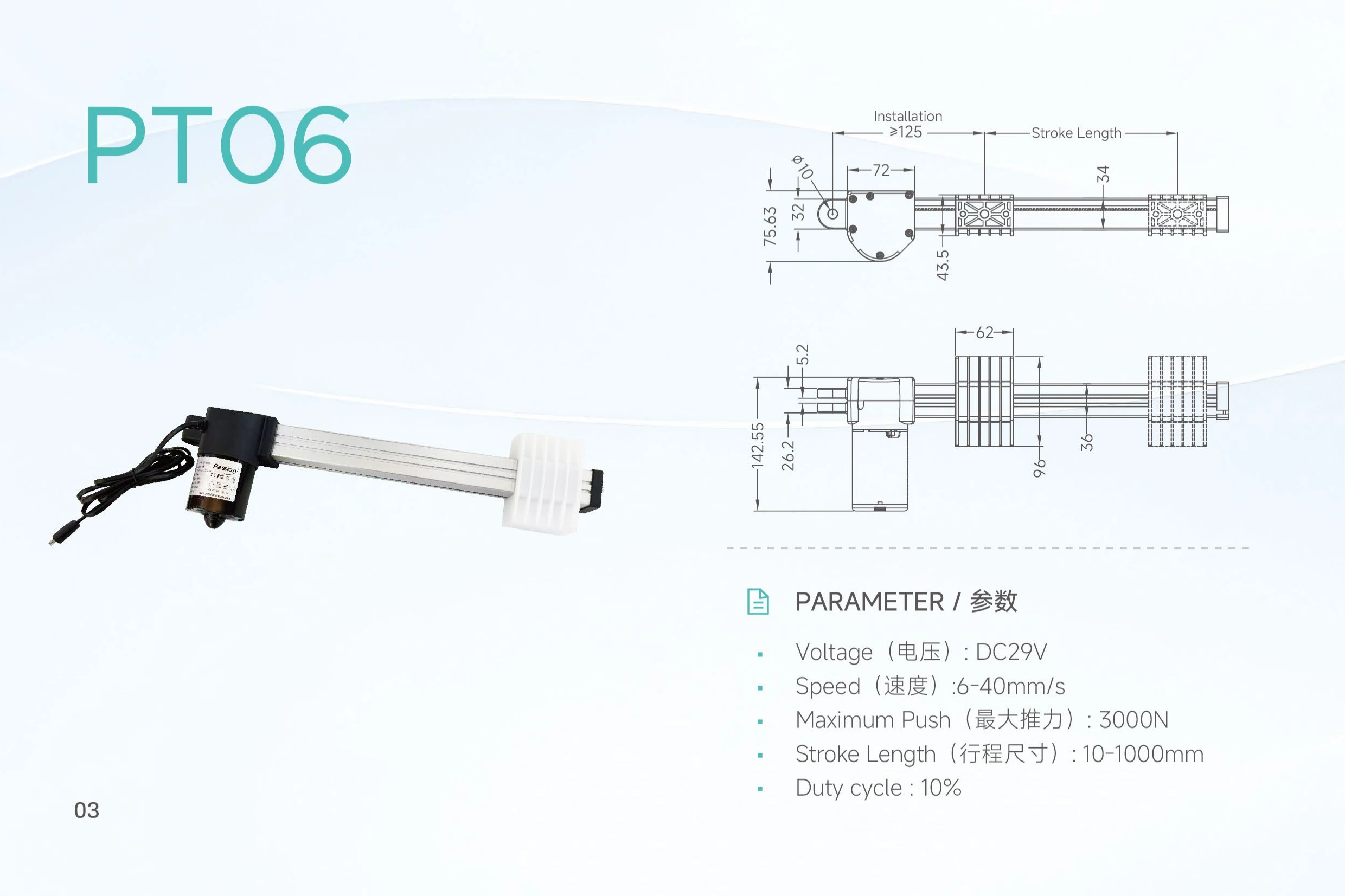
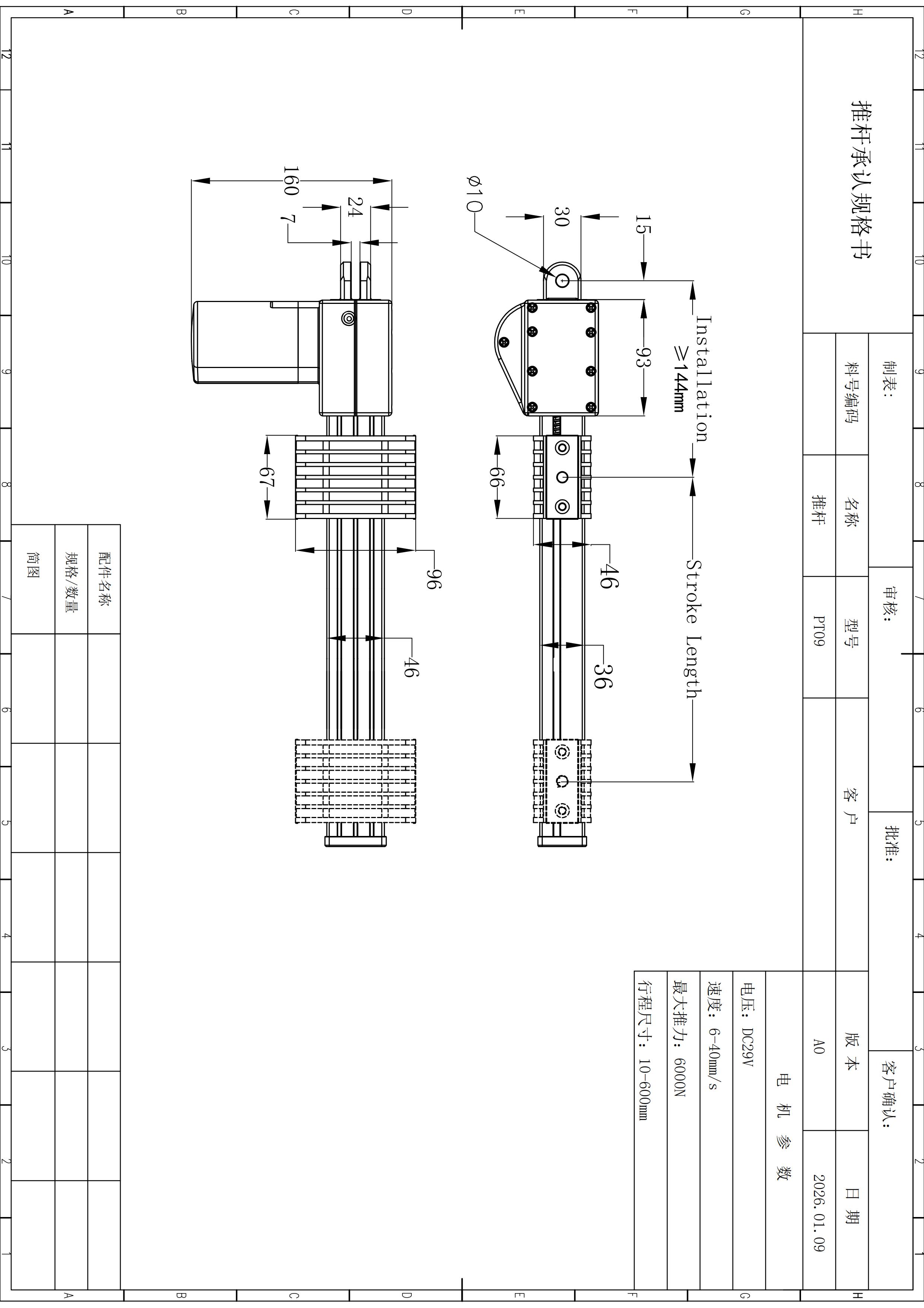
| Retracted installation offset | ≥92 mm | Use with the project drawing and surrounding clearances. |
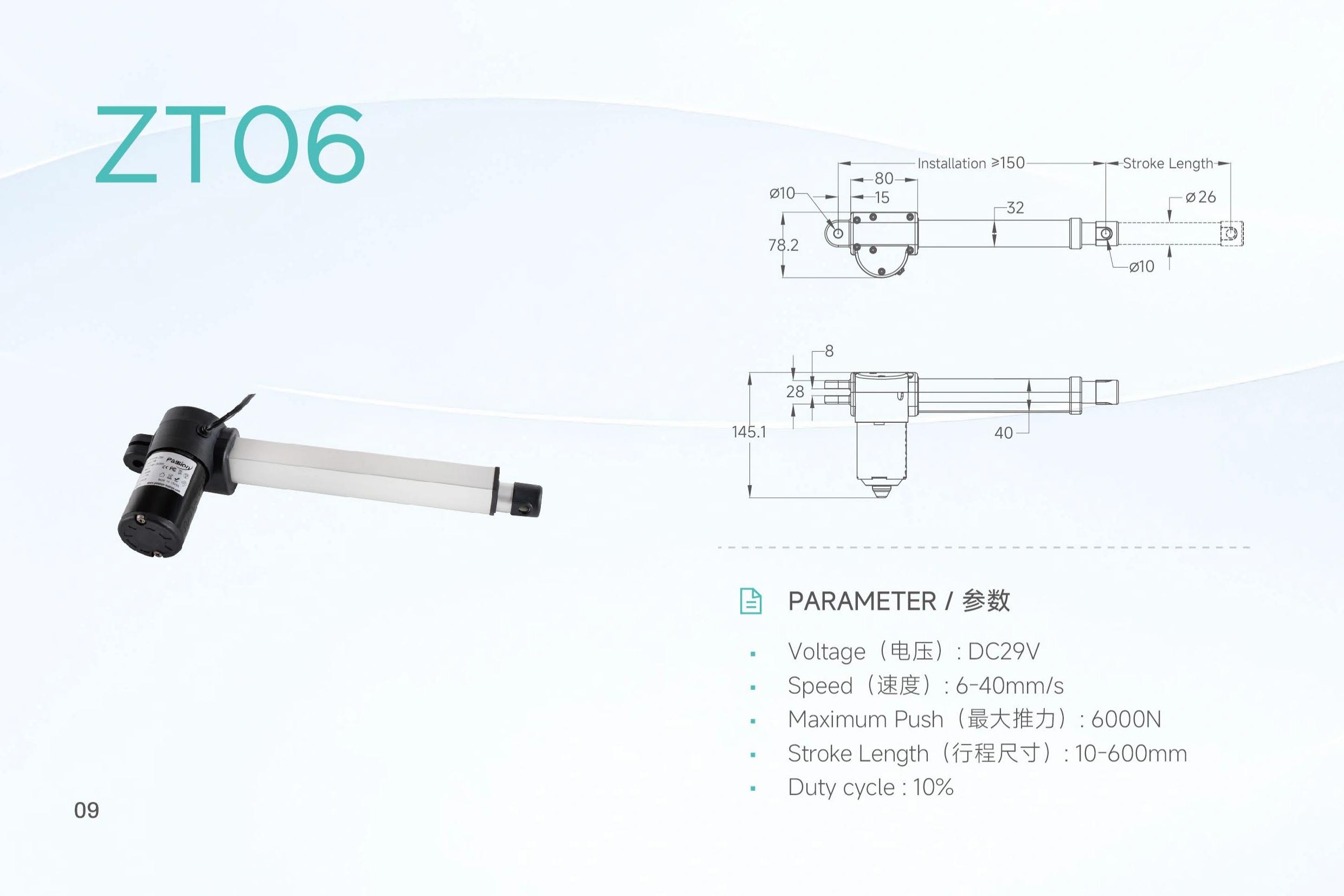
Move through the installation references without turning the drawing into a static wall of numbers.
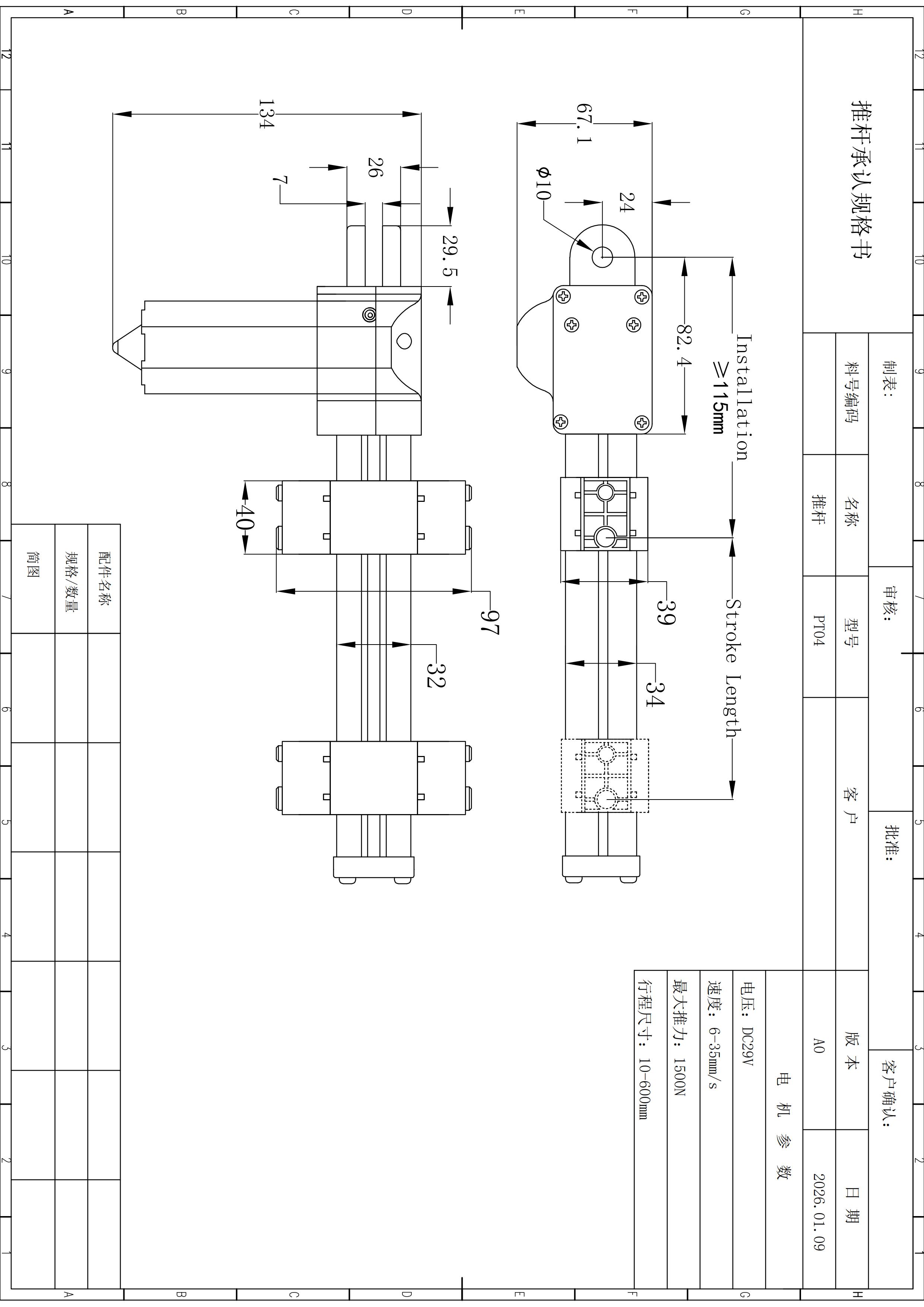
Select a geometry item to surface its role in the package. Final tolerances and manufacturing dimensions remain controlled by the released drawing.
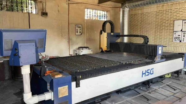
Show the production environment, then keep claims tied to controlled evidence.
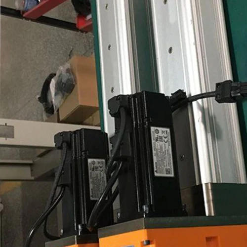
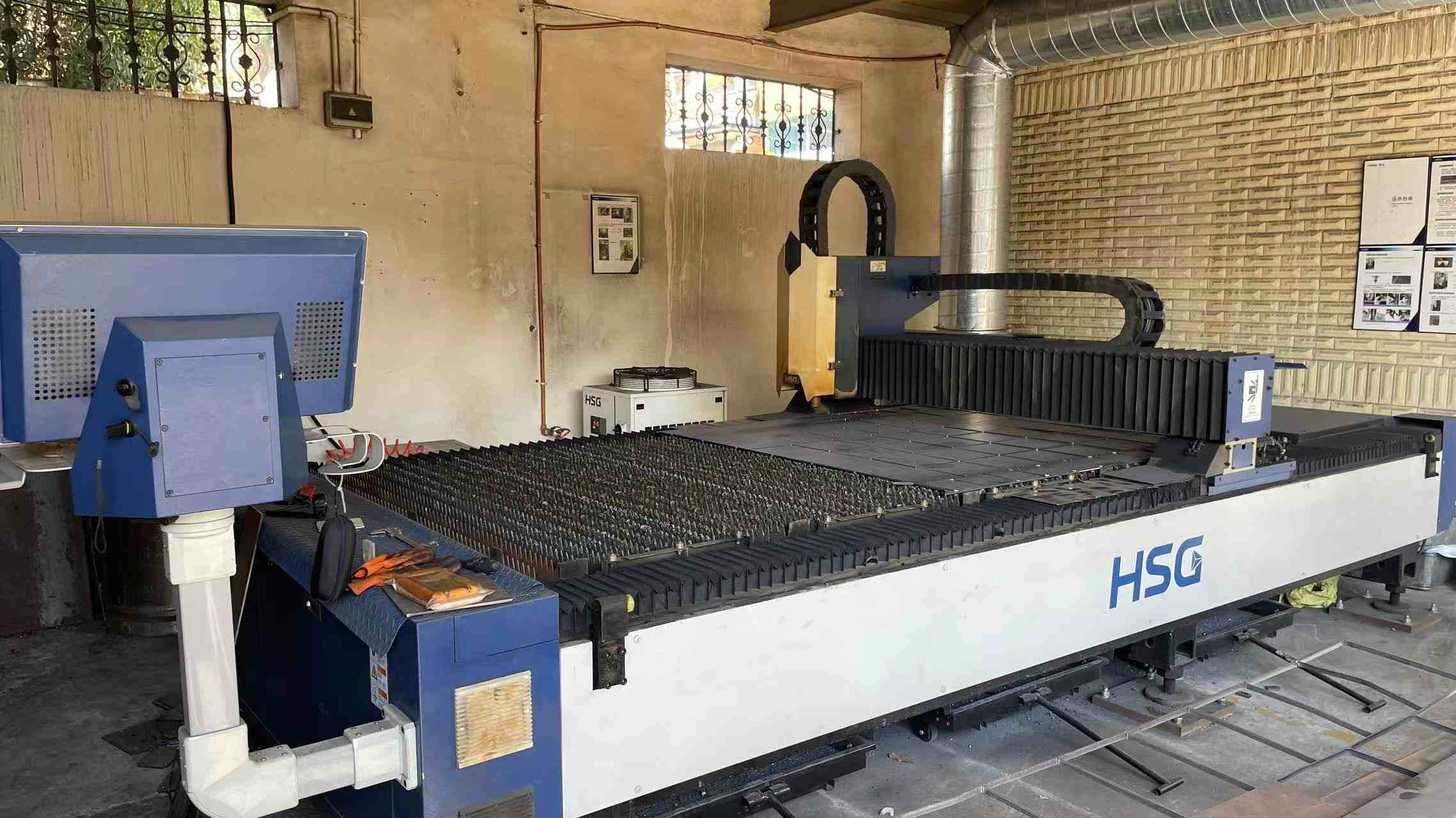
This first-party factory image is manufacturing context. It does not prove a PT18-specific process step, tolerance capability or certification status.
Long travel needs an envelope review before the structure is frozen.
Send working load, loaded speed, exact stroke, retracted fit, full carriage clearance, duty pattern, alignment / support conditions, environment, control requirements and document needs.
Long travel changes packaging questions before it changes the published headline specs.
Use this page to screen travel and package geometry; confirm loaded performance and support conditions before release.
What is the maximum push force?
The local PT18 record lists 3,000 N maximum push. Treat this as a maximum rating, not proof of a 3,000 N point at the highest published speed.
What stroke range is available?
The published stroke range is 10–1000 mm. Final selection should include retracted fit, carriage clearance and the surrounding machine envelope.
Does PT18 operate at 3,000 N and 50 mm/s at the same time?
That combined point is not verified by the available PT18 source. Submit both working load and loaded-speed requirements.
Does the travel rail calculate installation length?
No. It visualizes the selected stroke within the published range. Use the controlled drawing and project geometry to determine installation length and clearance.