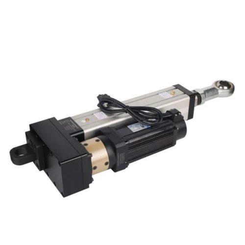
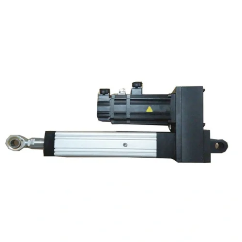
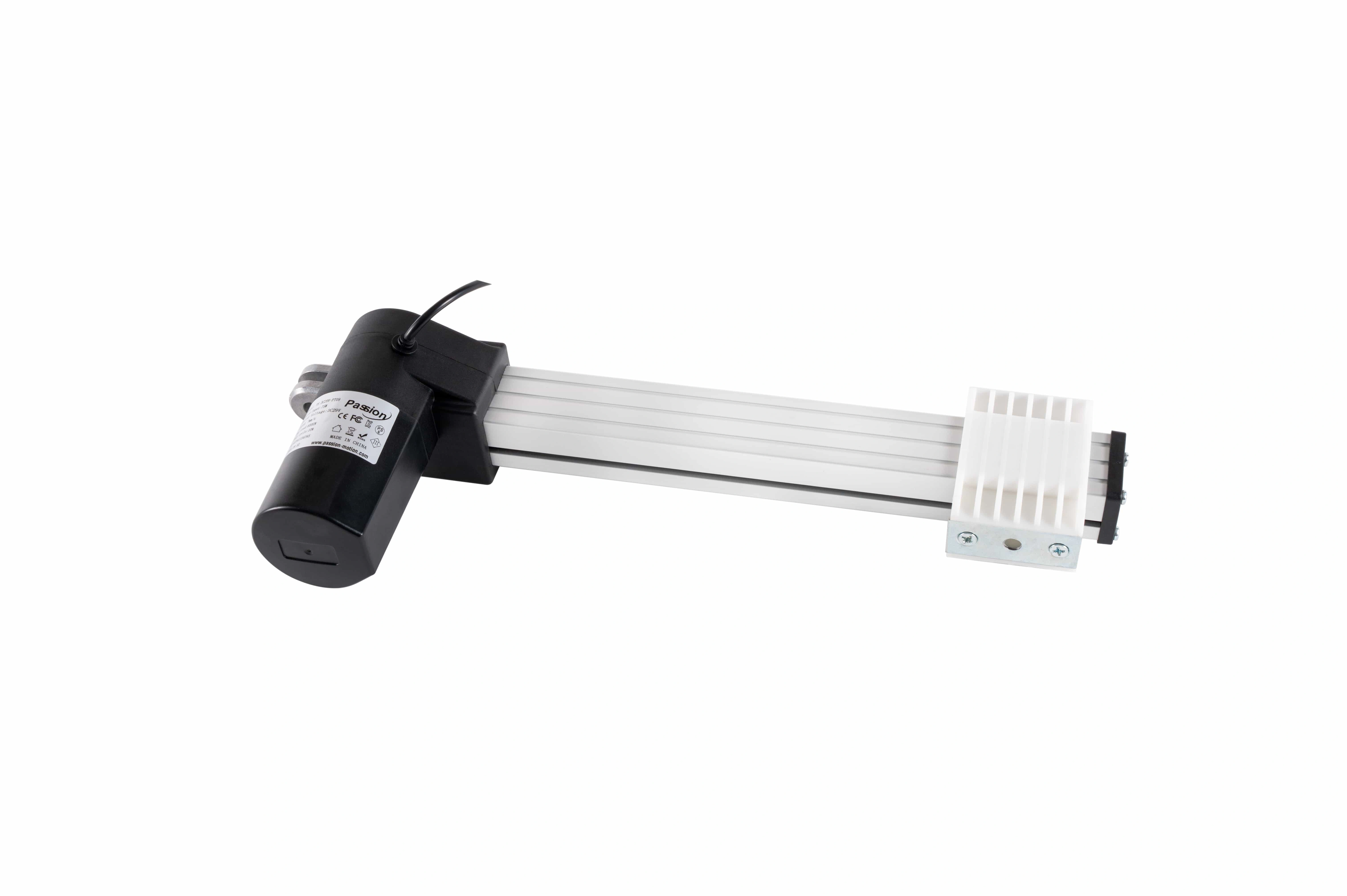
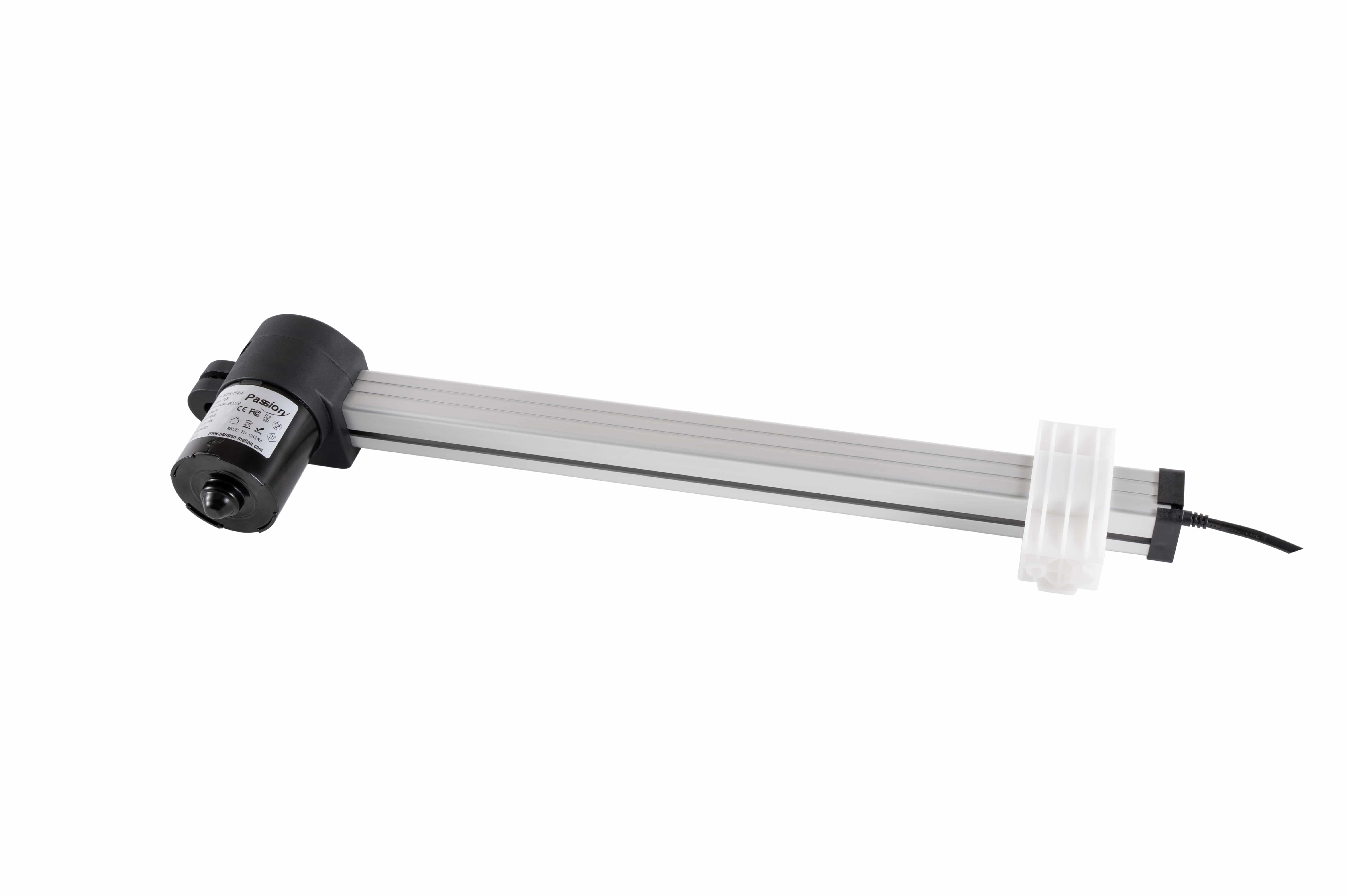
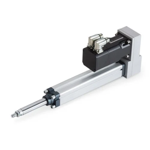
ZT12 Linear Actuator: 2500N, 1000mm Stroke
Review ZT12 specifications for DC29V operation, up to 2500N push, 6–40mm/s speed, 10–1000mm stroke, mounting references, and fit-review inputs.
Long travel changes the integration problem: the selected stroke must be checked with retracted geometry, extended clearance, alignment, swept path and surrounding structure. The published endpoints do not prove 2,500 N at 40 mm/s over 1,000 mm.
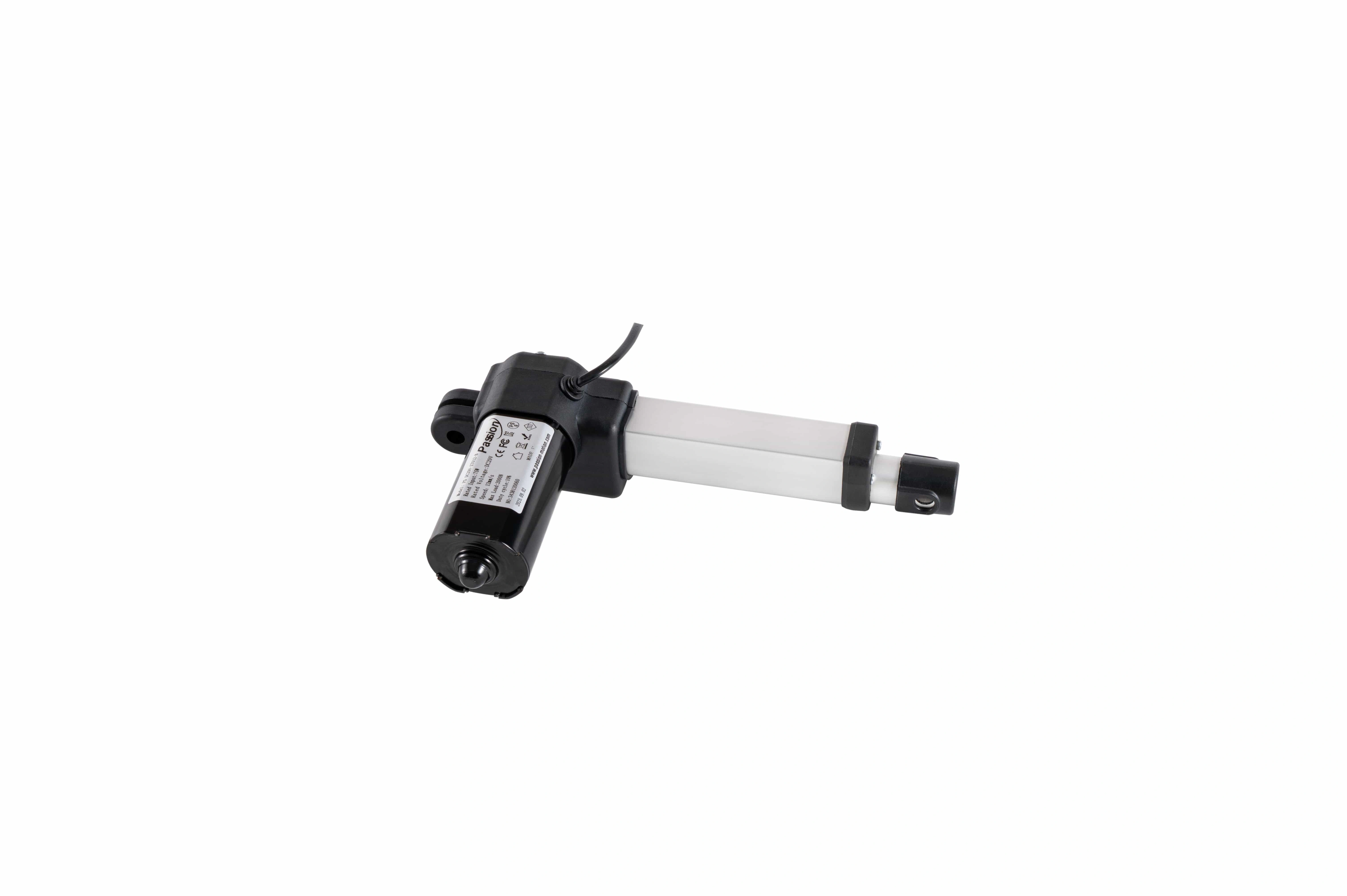
Separate force, speed and stroke before combining them in a real mechanism.
ZT12 publishes a 2,500 N push maximum, a 6–40 mm/s range and 10–1000 mm travel coverage. No source table proves that all three endpoints coexist.
| Parameter | Published value | Selection note |
|---|---|---|
| Input voltage | DC 29 V | Confirm released power, current capacity, connector and control arrangement. |
| Maximum push | Up to 2,500 N | Push rating only; pull force is not established in the locked source. |
| Speed | 6–40 mm/s | Loaded-speed conditions are not provided. |
| Stroke | 10–1000 mm | Confirm chosen travel together with retracted length, extended clearance and alignment. |
| Duty cycle | 10% | Time basis and test conditions are not stated. |
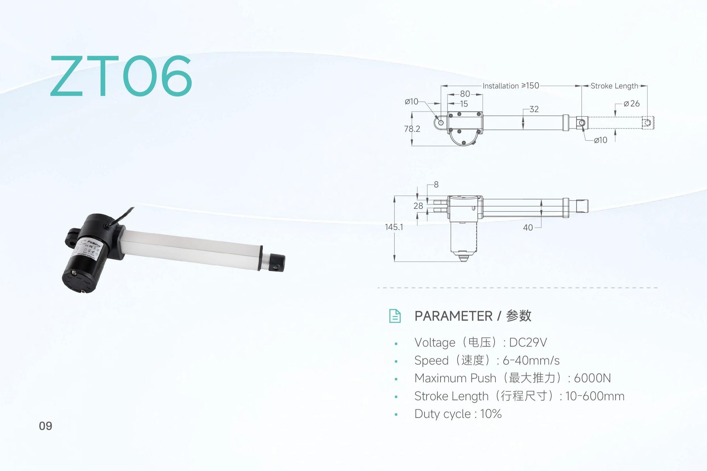
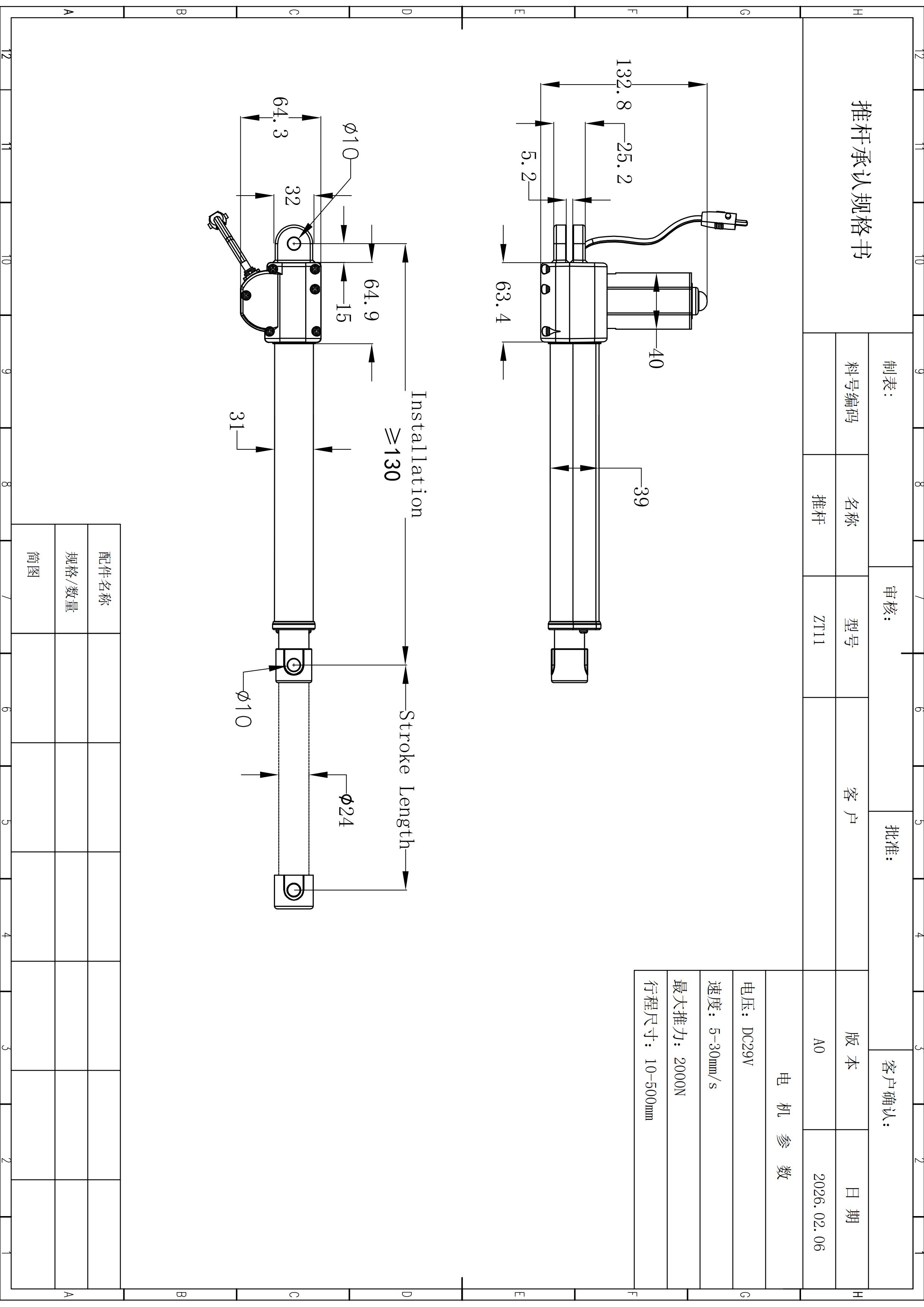
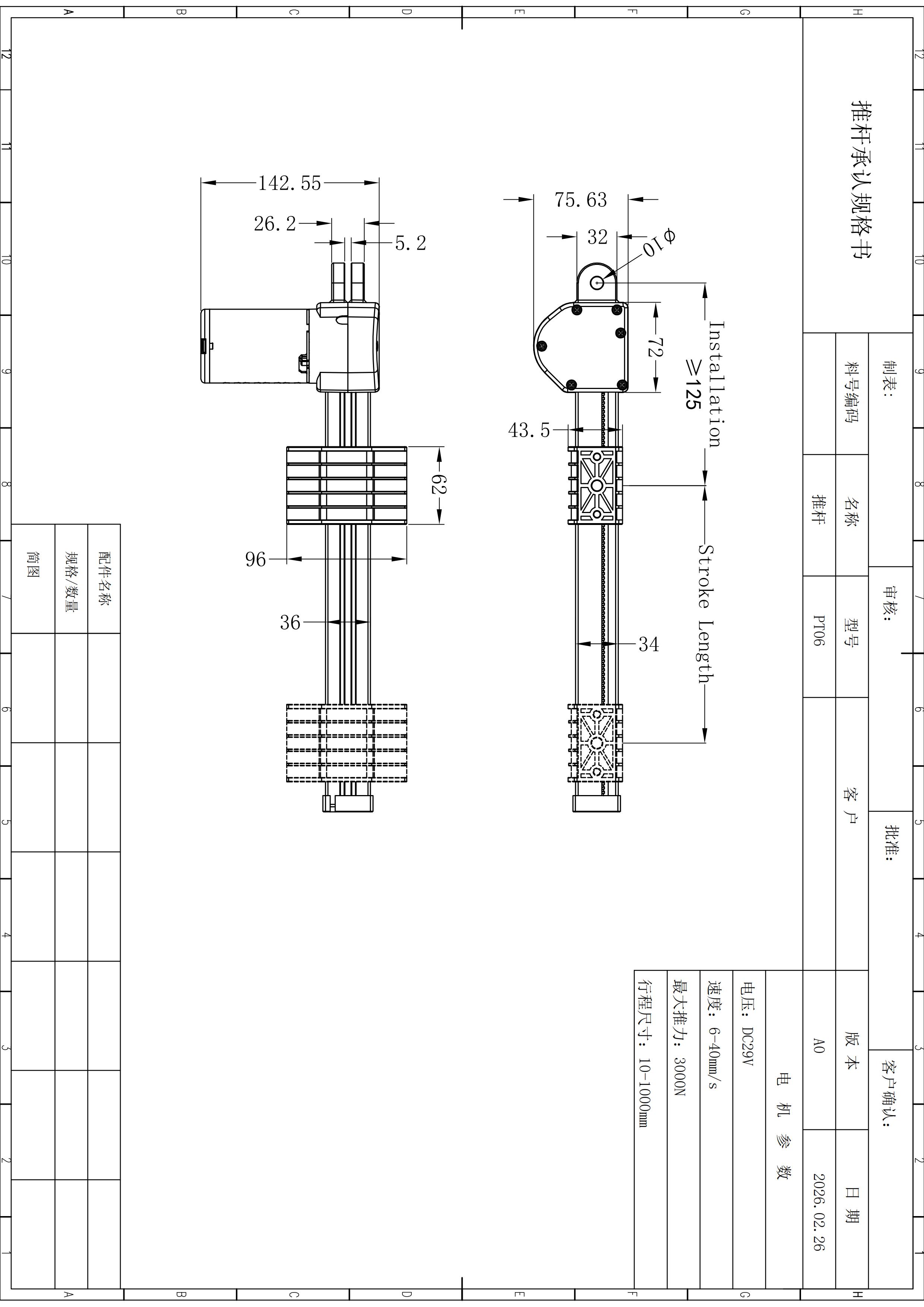
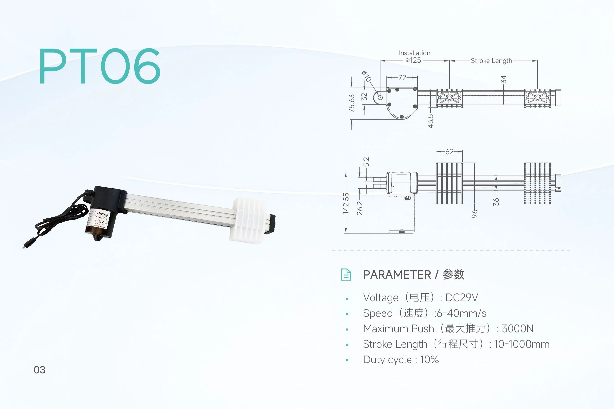
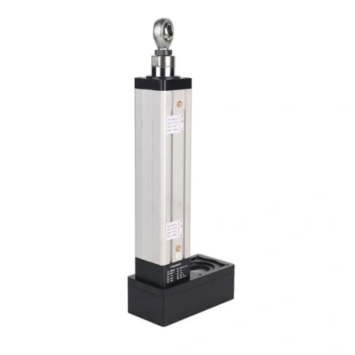
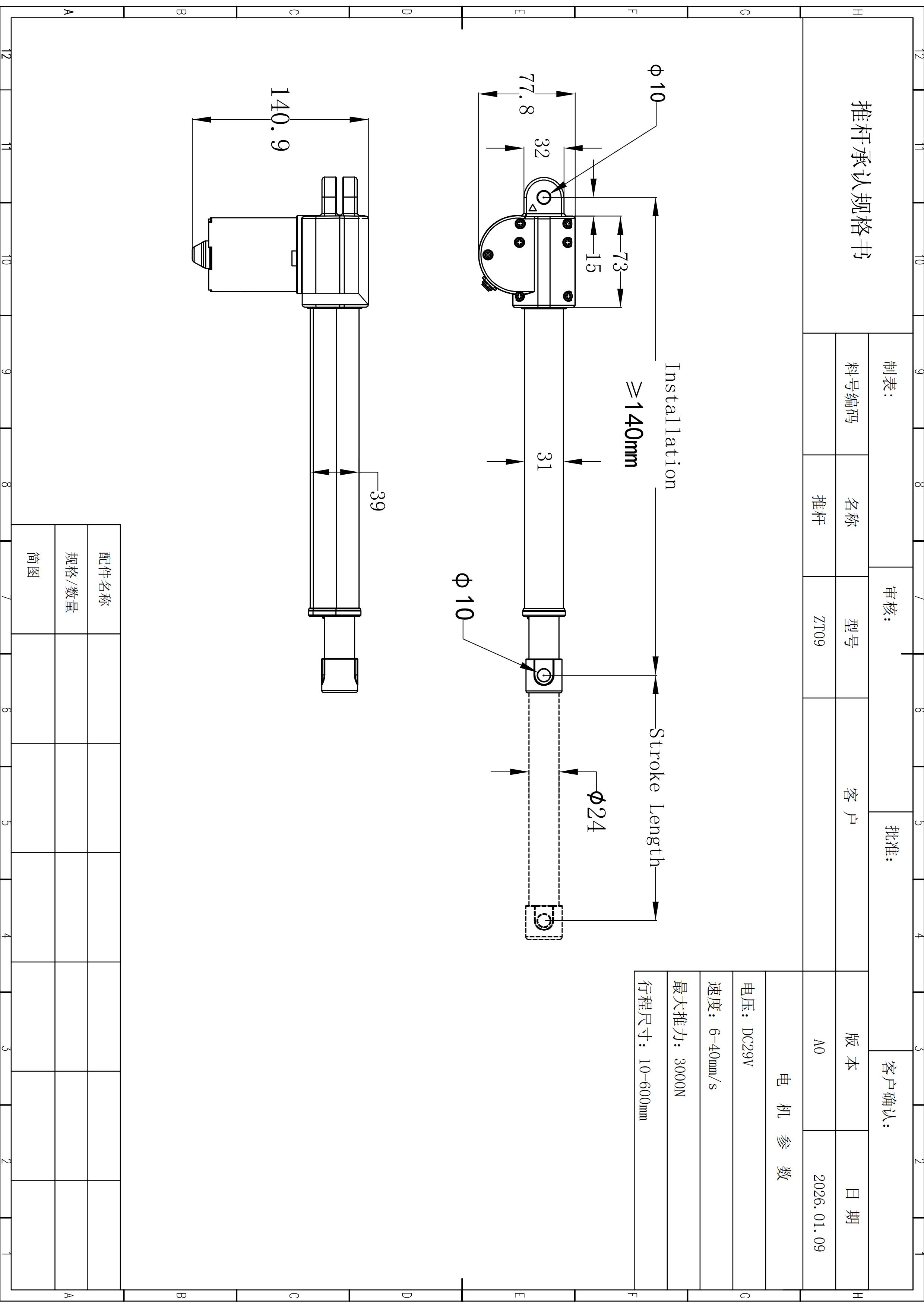
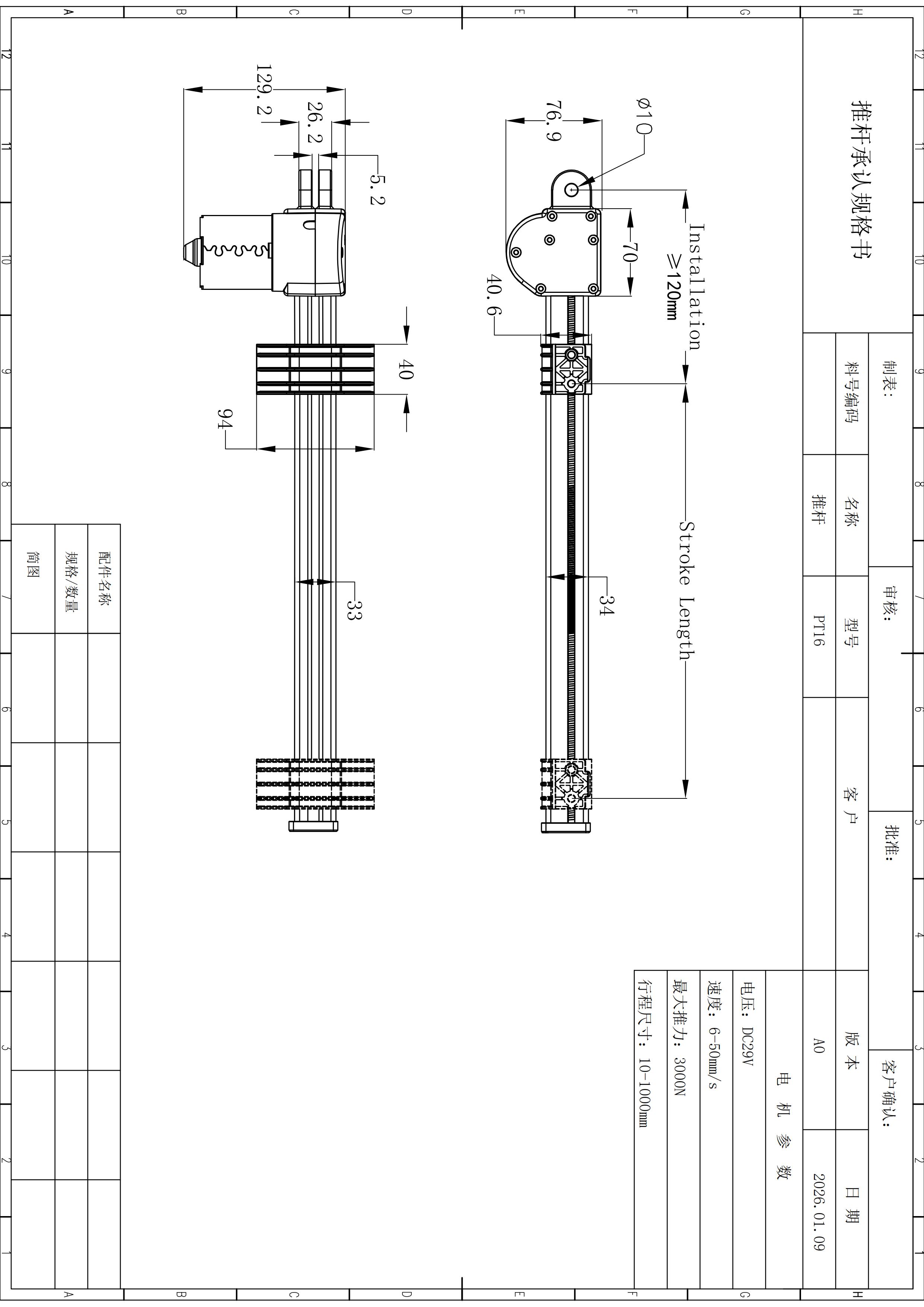
| Minimum installation distance | About 140 mm | Preliminary local drawing reference; verify on a released drawing. |
| Motor body height | 146 mm | Preliminary package reference. |
| Housing width | 68 mm | Preliminary package reference. |
| Cylinder outer diameter | Ø26 mm | Use for concept packaging only. |
| Pin hole diameter | Ø10 mm | Confirm mating pin and bracket geometry. |
Preview how travel changes the space the mechanism must reserve.
The rail is an explanatory motion model, not a released dimension drawing. Its purpose is to keep stroke, full extension, swept clearance and side-load risk in the same engineering conversation.
Do not confuse minimum installation reference with closed length for every stroke.
The local record gives about 140 mm as a preliminary minimum installation distance. Final pin-to-pin geometry still depends on the selected build.
Inspect the mechanism before the endpoint.
Long travel can amplify misalignment. Check guide path, changing leverage and adjacent structure throughout motion, not only at both ends.
Reserve the complete extended envelope.
The 1,000 mm figure is the published stroke limit, not proof of one universal extended installation dimension or load-speed combination.
Keep the complete motion corridor clear.
Check motor body, cable path, service access, bracket freedom and any structure that could interfere during extension or retraction.
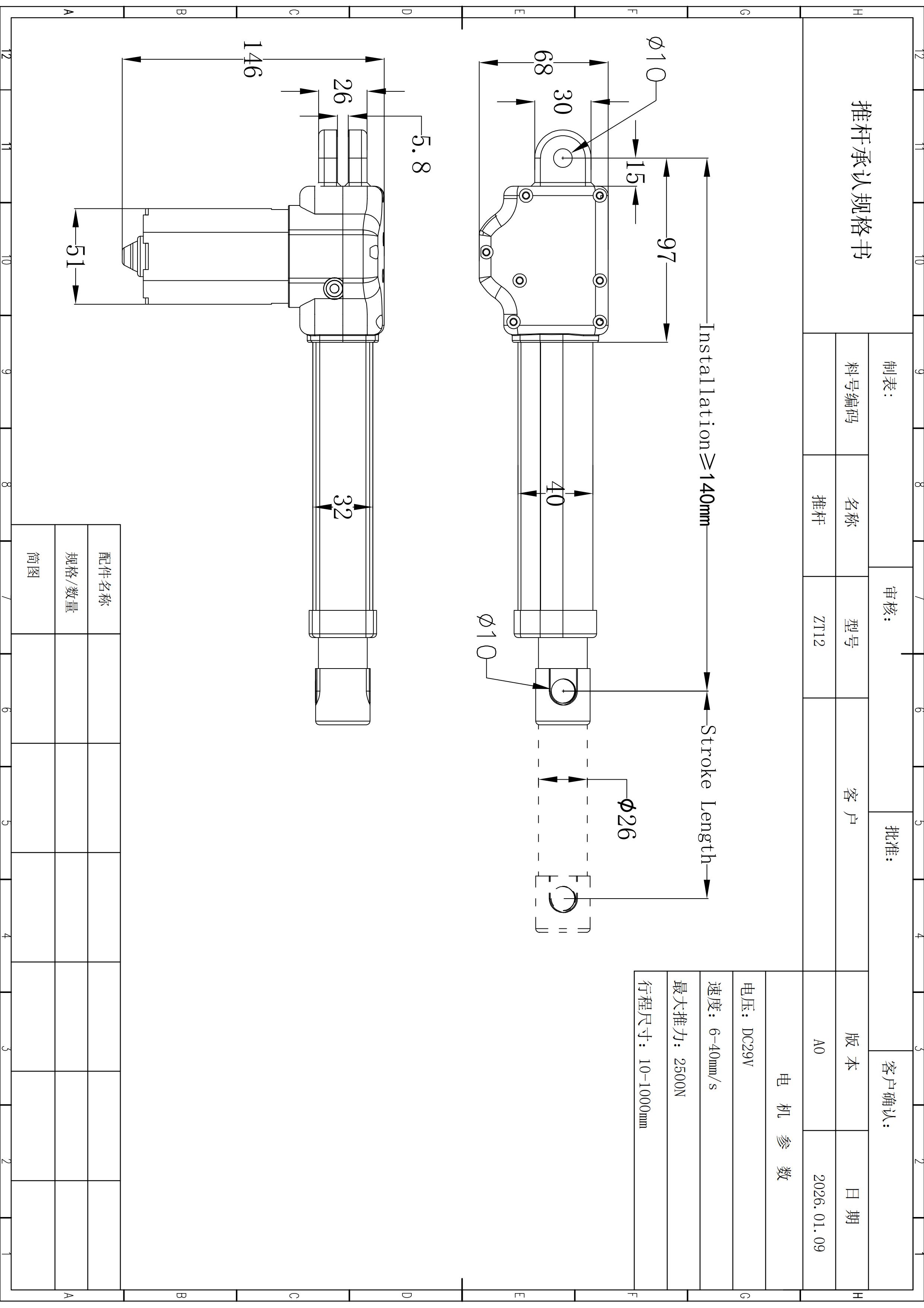
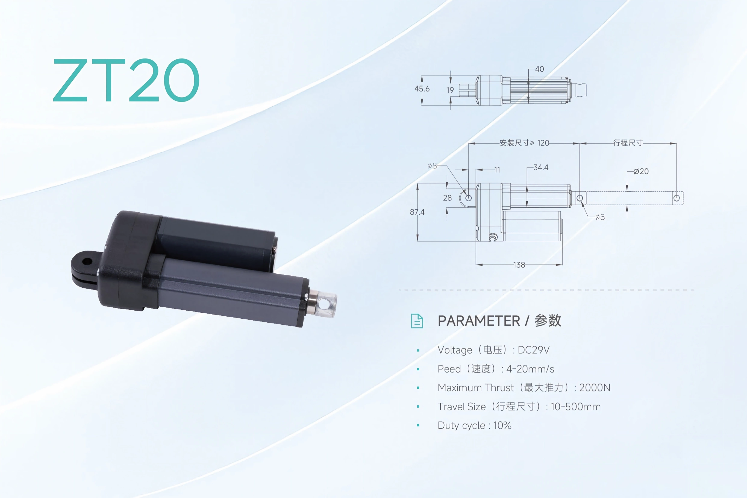
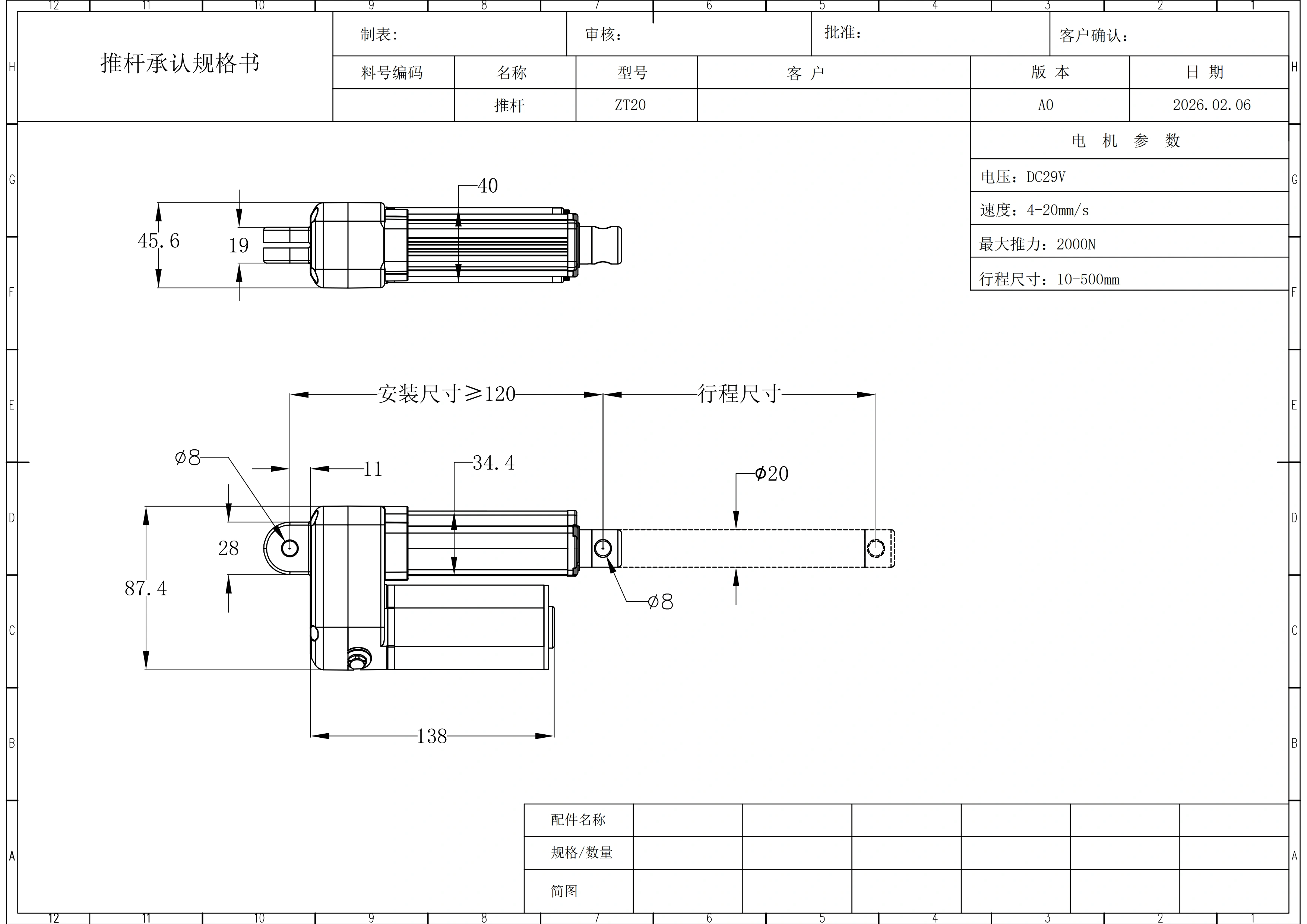
Long stroke requires the released geometry.
Use this source image to inspect the recorded package dimensions, then release brackets and endpoint clearance only against the current technical drawing for the selected stroke.
Review the long-travel mechanism as one system.
Provide the actual working load and loaded speed together with selected stroke, retracted space, mechanism geometry, cycle, environment, control and release documents.
Needs confirmation before release
2,500 N at 40 mm/s over 1,000 mm, pull force, current draw, startup current, feedback, synchronization, endpoint logic, environmental rating and final long-stroke geometry are not established in the locked ZT12 source.
Define ZT12 with load, speed and travel in the same request.
Send working load + direction + required loaded speed + stroke + retracted space + full motion clearance + cycle + control / power needs + quantity .
Treat 1,000 mm as a travel boundary, not a shortcut to final geometry.
The verified local record supports DC29V, up to 2,500 N push, 6–40 mm/s, 10–1000 mm stroke, 10% duty and preliminary mounting references.
Can ZT12 deliver 2,500 N at 40 mm/s?
That operating point is not established by the available source. Force maximum and speed range are published independently.
Is every 1,000 mm stroke build the same closed length?
No such rule is established. Stroke is travel; the selected build still requires released retracted and extended geometry.
What mounting references are published?
The record lists about 140 mm minimum installation distance, 146 mm motor body height, 68 mm housing width, Ø26 mm cylinder diameter and Ø10 mm pin hole.
What does the 10% duty cycle mean in minutes?
The source does not state a time basis or test conditions, so the percentage should not be converted into a fixed schedule without review.
Are synchronized motion and environmental ratings confirmed?
Those items are not established in the available ZT12 evidence and should be specified for configuration review.