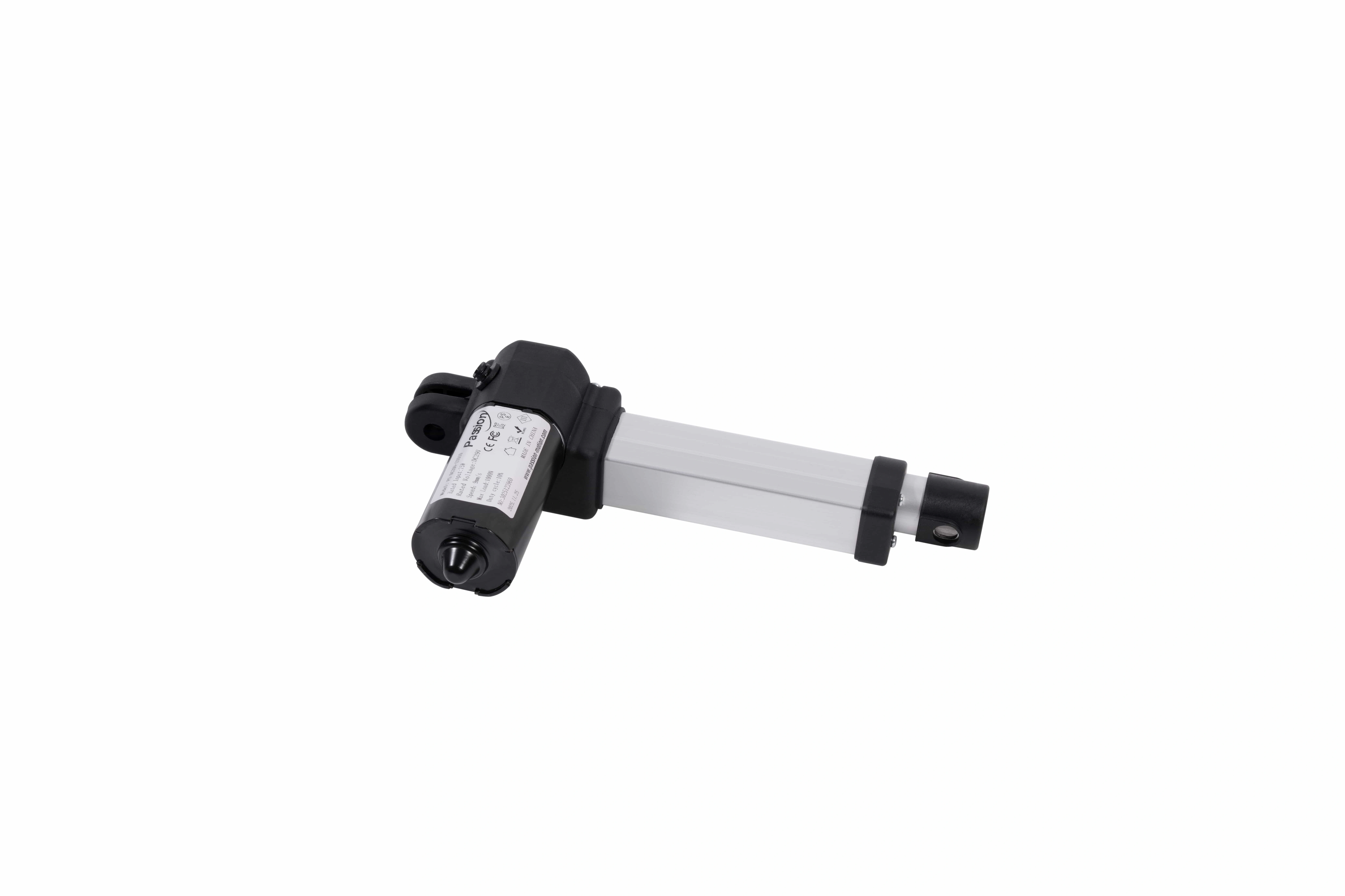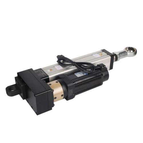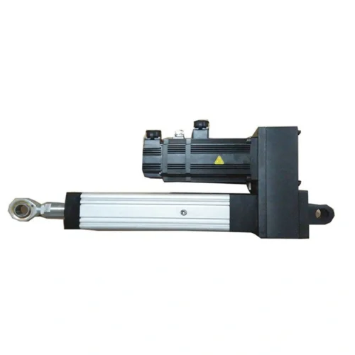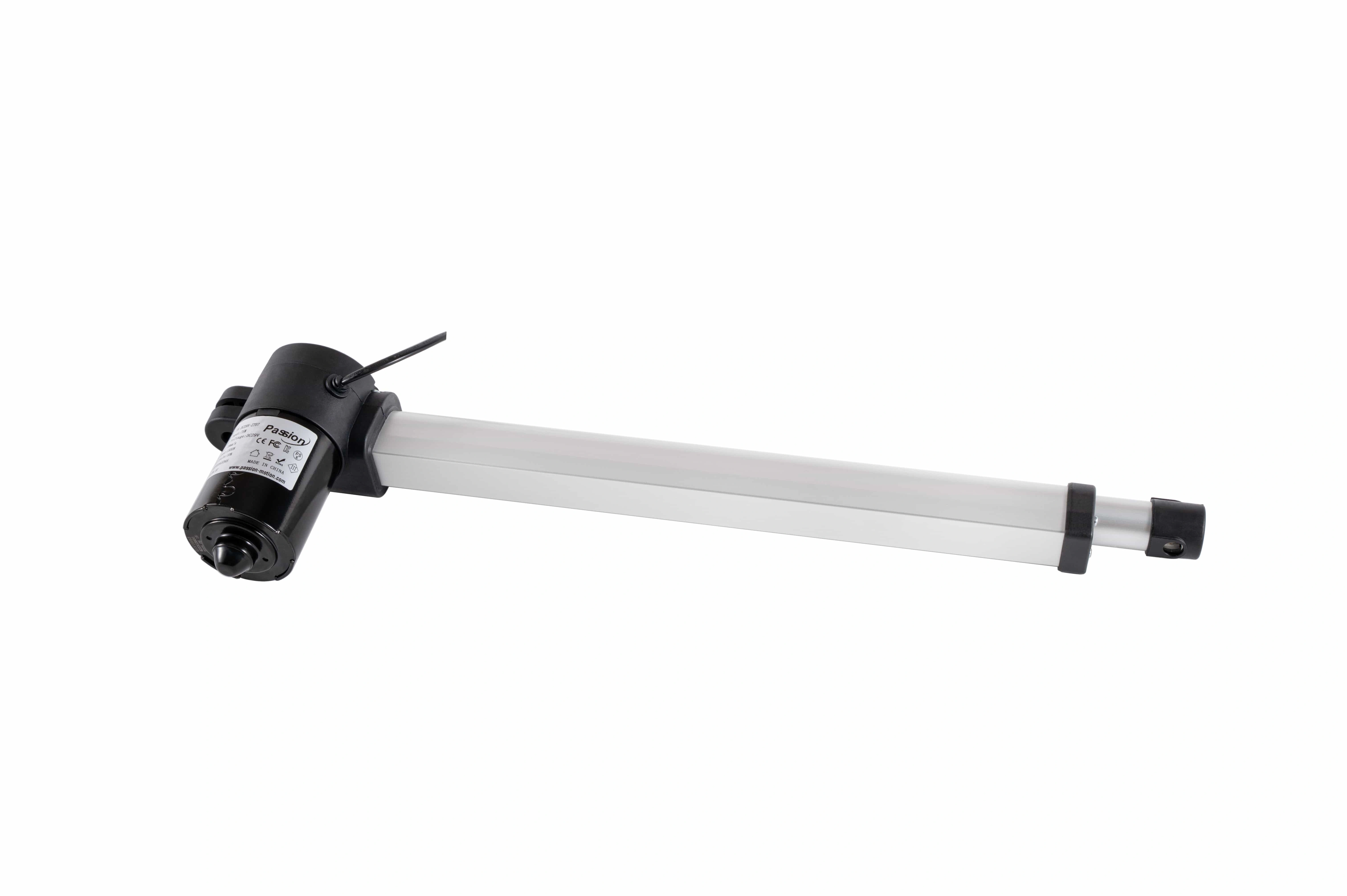
ZT17 Linear Actuator: 2000N, 3–8mm/s
Review ZT17 specifications for DC29V operation, up to 2000N push, 3–8mm/s speed, 10–500mm stroke and compact mounting references.
ZT17 Linear Actuator
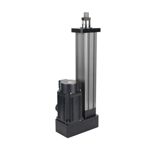
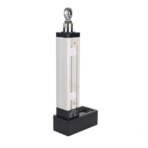
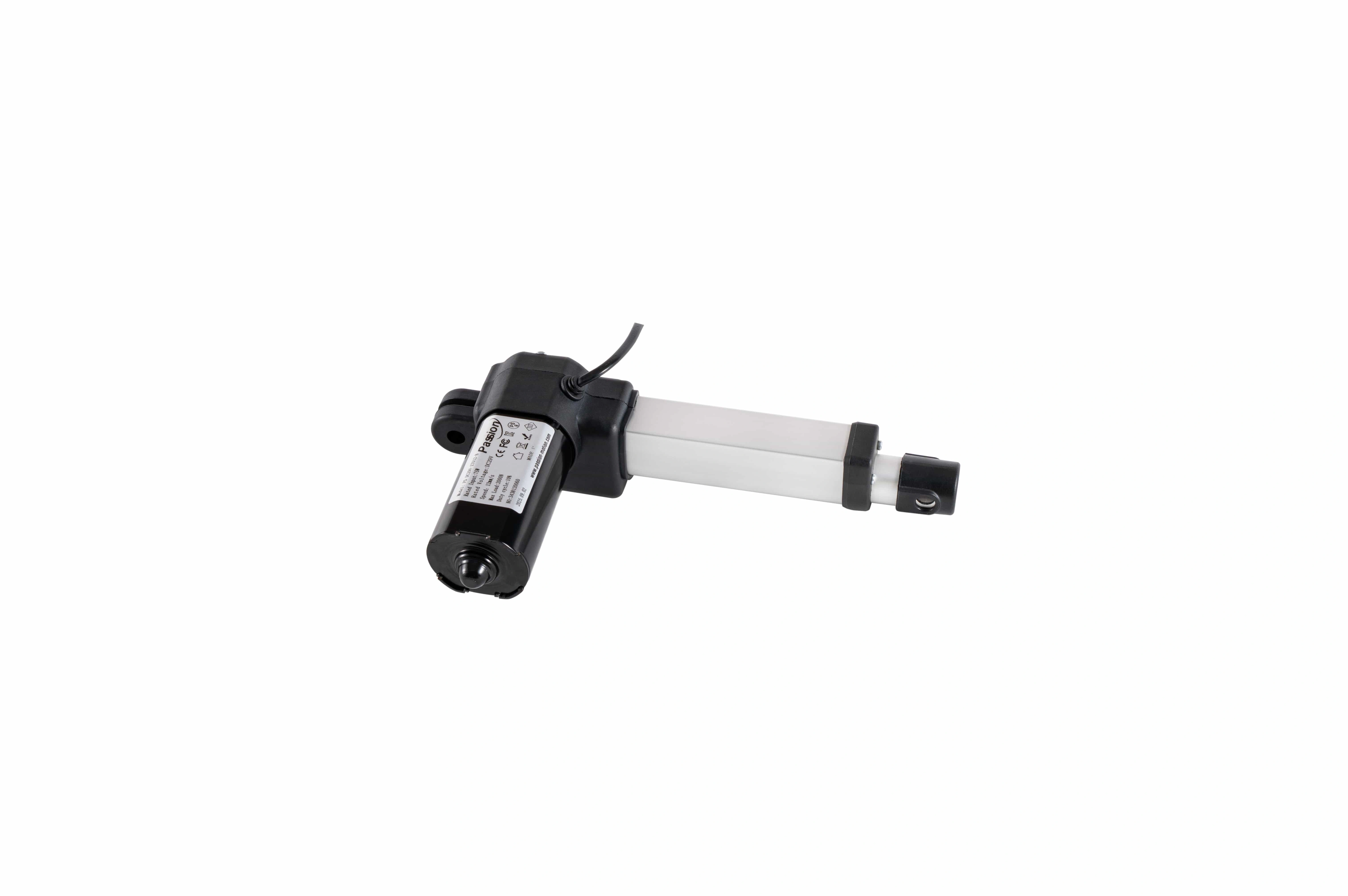
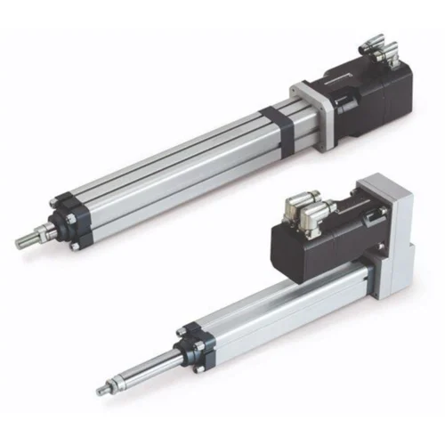
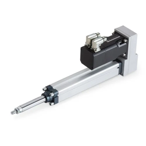
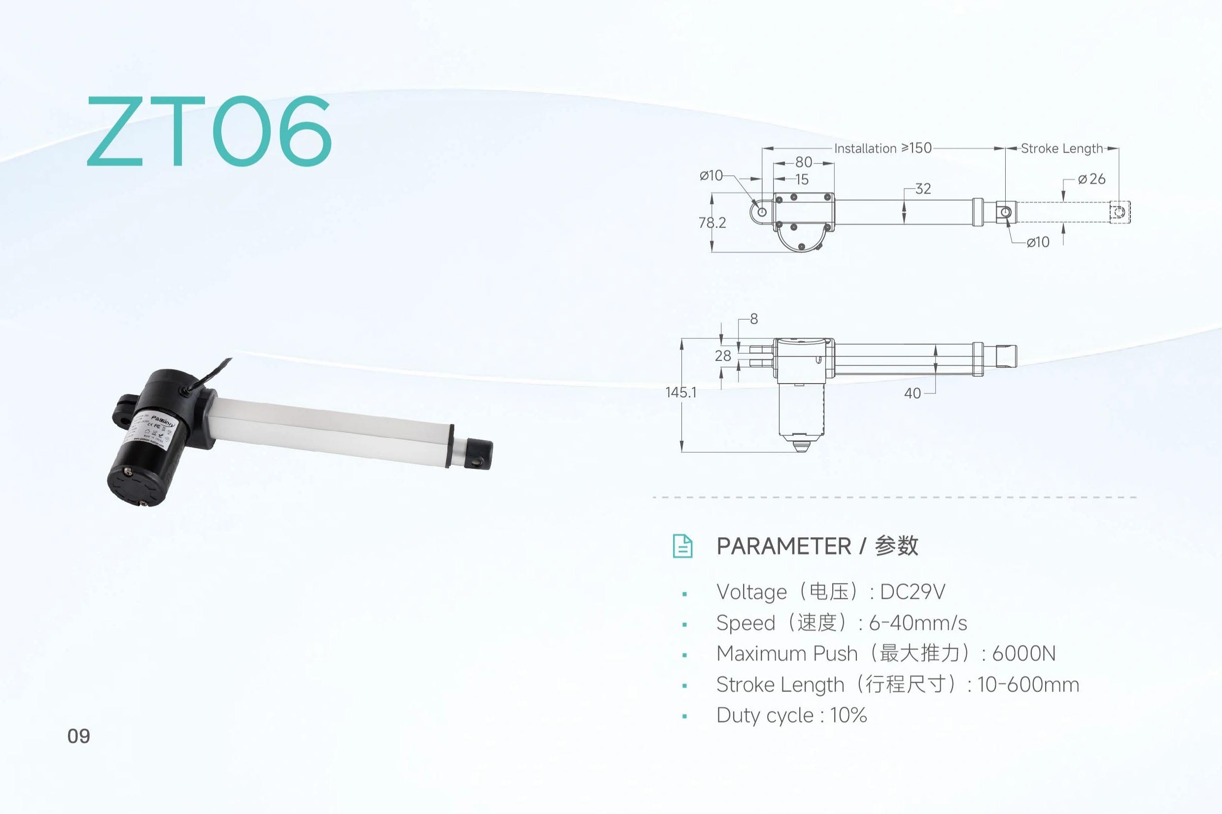
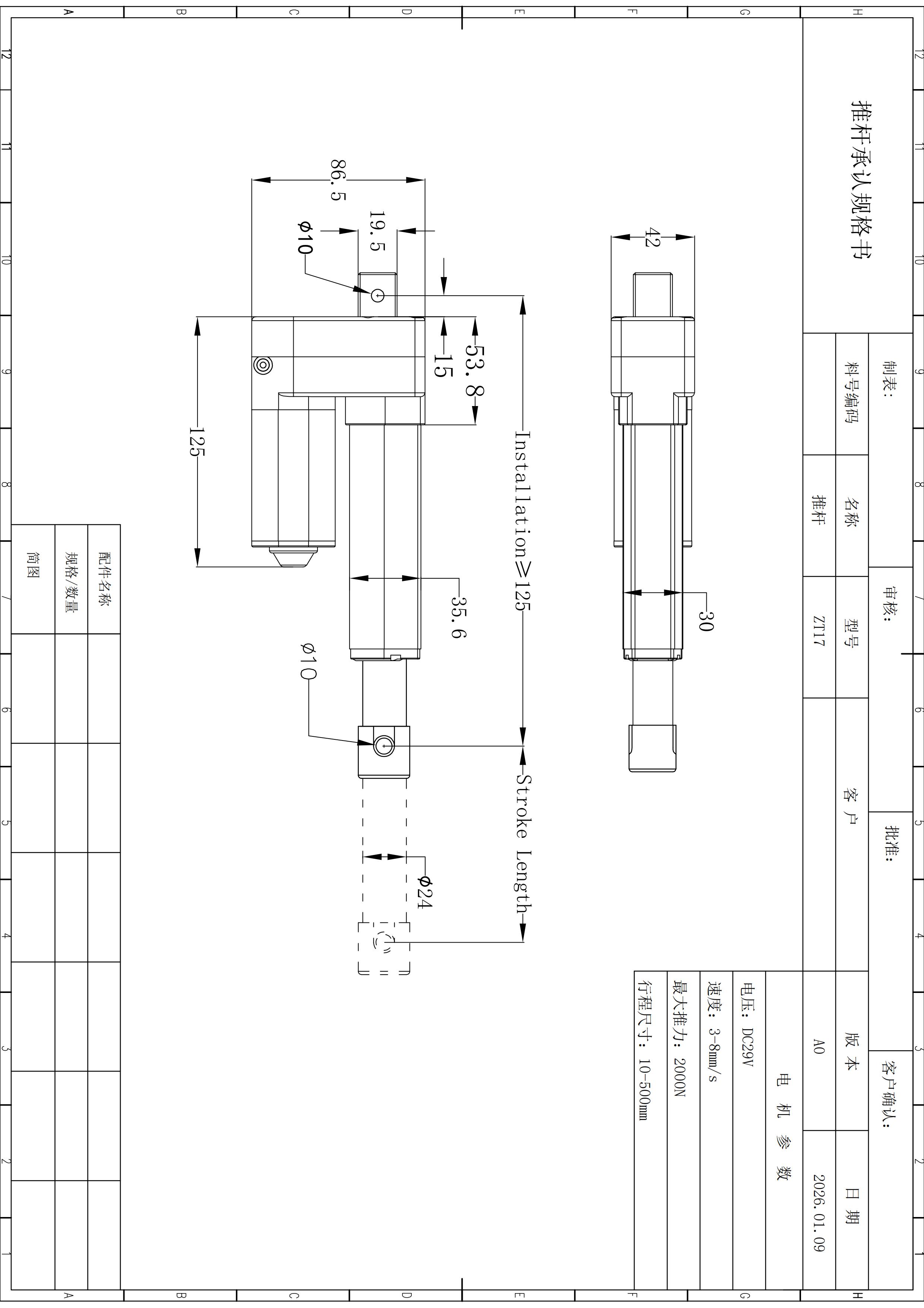
A DC 29 V model centered on controlled low-speed movement: up to 2,000 N maximum push , a published 3–8 mm/s speed range and 10–500 mm stroke options, with a compact installation reference beginning at ≥125 mm .
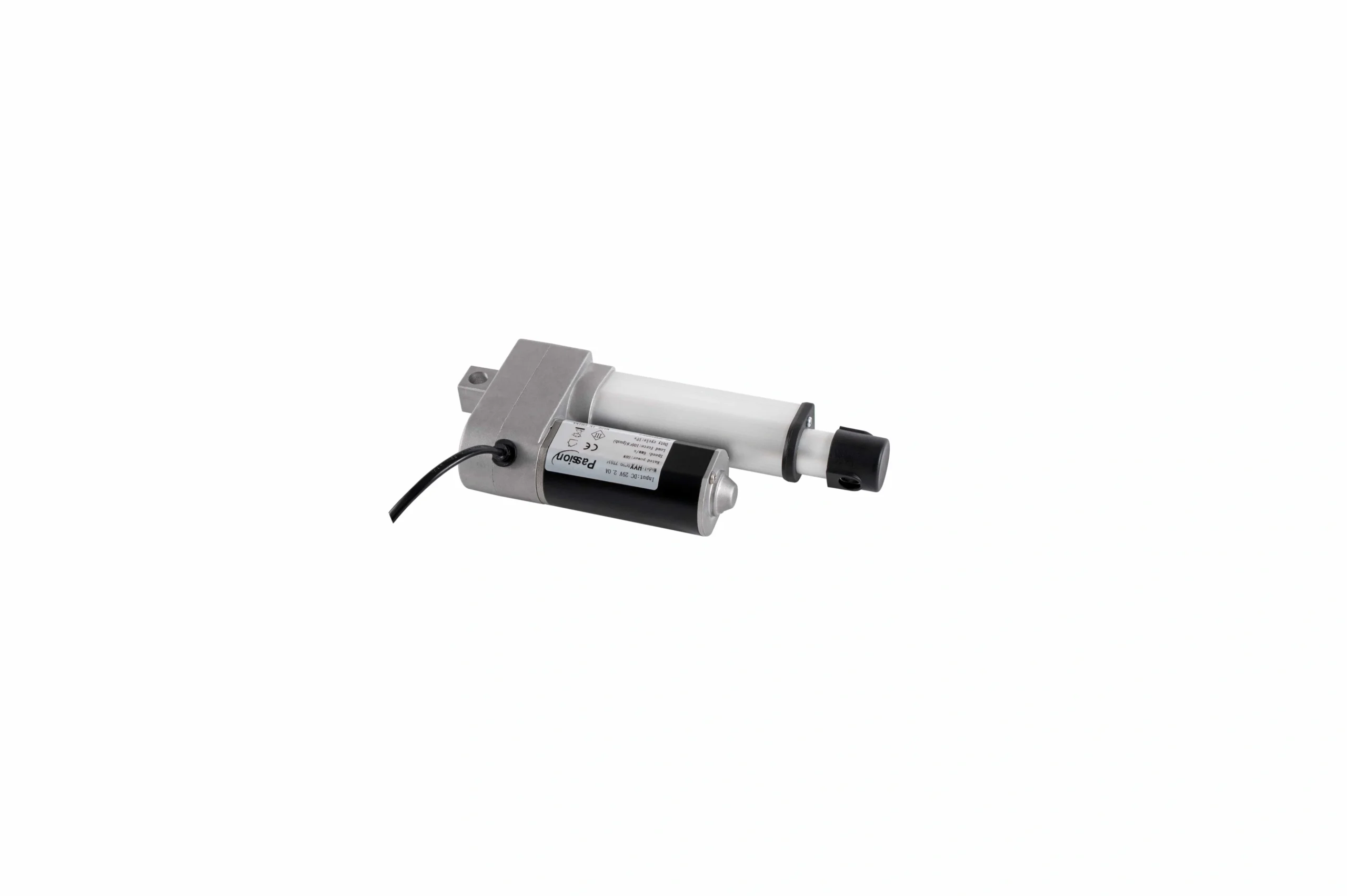
Use the low-speed range as a selection signal, not proof of a force-speed pair.
The available record publishes up to 2,000 N push and a 3–8 mm/s speed range separately. A force-speed curve or loaded-speed matrix is not present.
| Parameter | Published value | Selection note |
|---|---|---|
| Input voltage | DC 29 V | Confirm power and control details for the released configuration. |
| Maximum push | Up to 2,000 N | Push rating only; pull force is not established in the locked source. |
| Speed | 3–8 mm/s | Published range; loaded-speed conditions are not provided. |
| Stroke | 10–500 mm | Confirm travel and final installation geometry. |
| Duty cycle | 10% | Time basis and test conditions are not stated. |
| Installation dimension | ≥125 mm | Preliminary reference; verify against released drawing. |
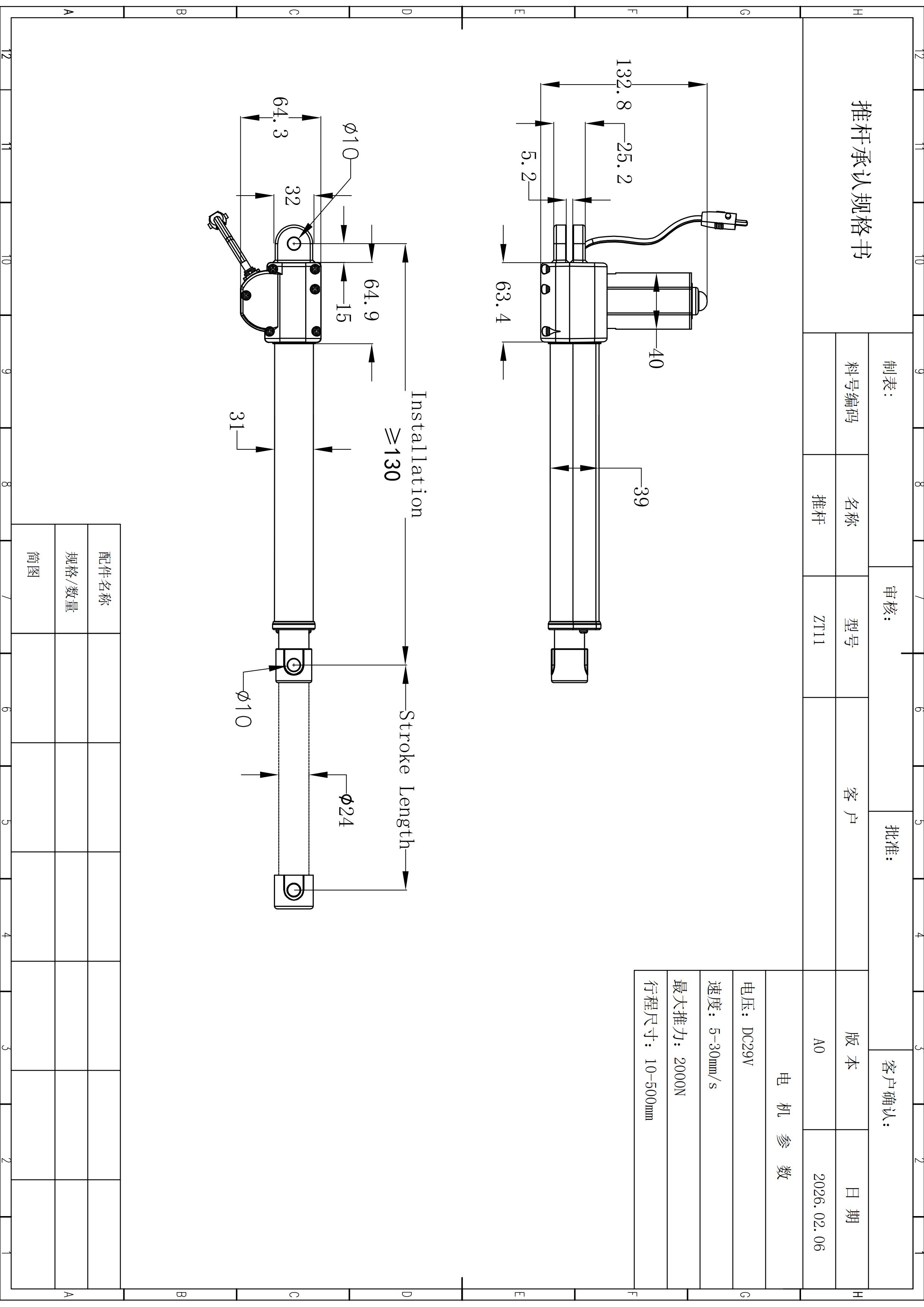
| Profile height | 86.5 mm | Use for early package checks. |
| Motor width | 42 mm | Confirm surrounding clearance. |
| Outer / inner tube | 30 / 24 mm | Preliminary dimensional references. |
| Clevis hole | Ø10 mm | Confirm mating pin and bracket fit. |
| Base hole offset | 19.5 mm | Verify final datum on the current drawing. |
Compare the published speed band as a motion-control decision.
The animated marker is deliberately illustrative: it shows relative pace only. It does not claim a loaded travel time or prove 2,000 N at any selected speed.
Use slow motion deliberately.
Where controlled movement matters more than rapid repositioning, state the actual working load and verify the required speed under that load.
Define the speed the mechanism actually needs.
A middle-band target can be more useful than choosing an endpoint. Combine loaded speed with load direction, stroke and cycle.
Do not assume maximum push at the upper speed.
The source does not establish 2,000 N at 8 mm/s. Send the intended load-speed point for verification.
Translate duty into the real run/rest pattern.
The record gives a percentage but no time basis. State moves per cycle, cycles per hour and expected on/off timing.
Keep the slow-motion requirement tied to the real package.
Inspect the published mounting references together with the mechanism path, motor clearance and cable routing. Final geometry still requires the current released drawing.
Make the speed requirement measurable under the expected load.
ZT17 is most useful when the inquiry states the working load and the required speed together, then adds stroke, package space, cycle, environment, power/control and release documents.
Needs confirmation before release
2,000 N at 8 mm/s, pull force, current draw, startup current, feedback, controller pairing, positioning accuracy, environmental rating and model-specific compliance evidence are not established in the locked ZT17 source.
Define the ZT17 requirement around loaded speed.
Send working load + direction + required loaded speed + stroke + installation space + mechanism geometry + duty pattern + power/control needs + quantity .
Use the 3–8 mm/s range as an engineering boundary.
The verified source supports DC29V, up to 2,000 N push, 3–8 mm/s, 10–500 mm stroke, a 10% duty figure and the listed compact mounting references.
Can ZT17 deliver 2,000 N at 8 mm/s?
That operating point is not established. The source publishes maximum push and speed range separately without a force-speed table.
What stroke lengths are published?
The local record lists 10–500 mm. Final retracted space, extended clearance and bracket positions still depend on the selected build.
What compact mounting references are available?
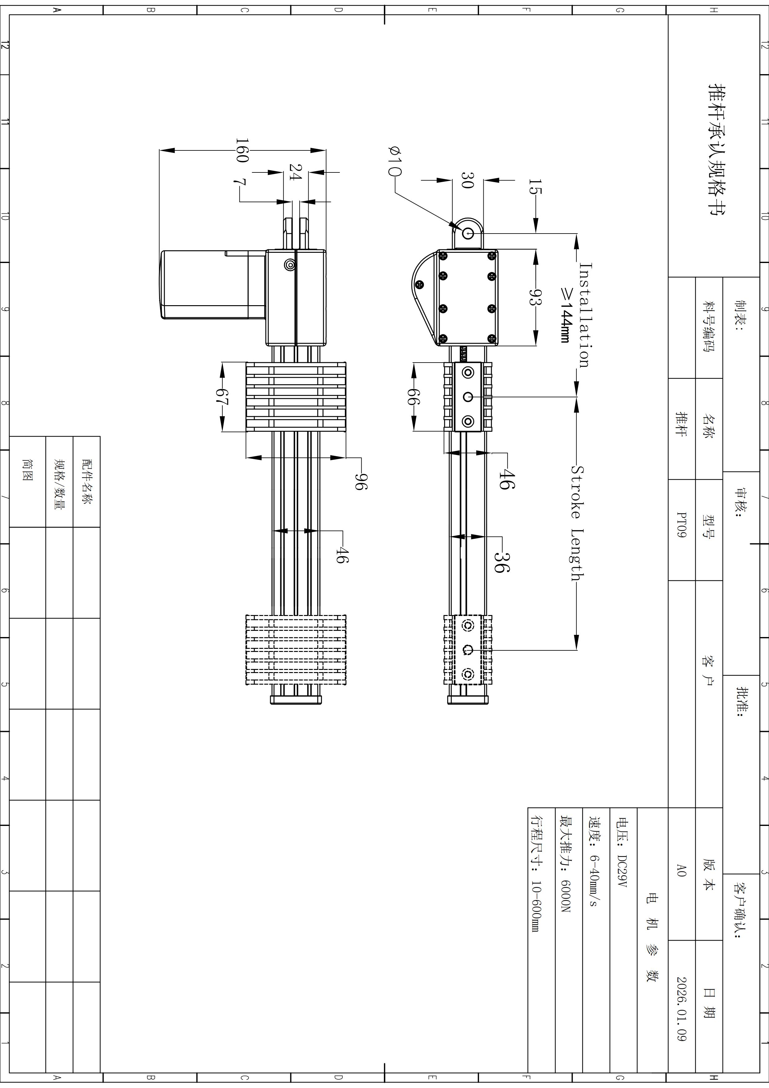
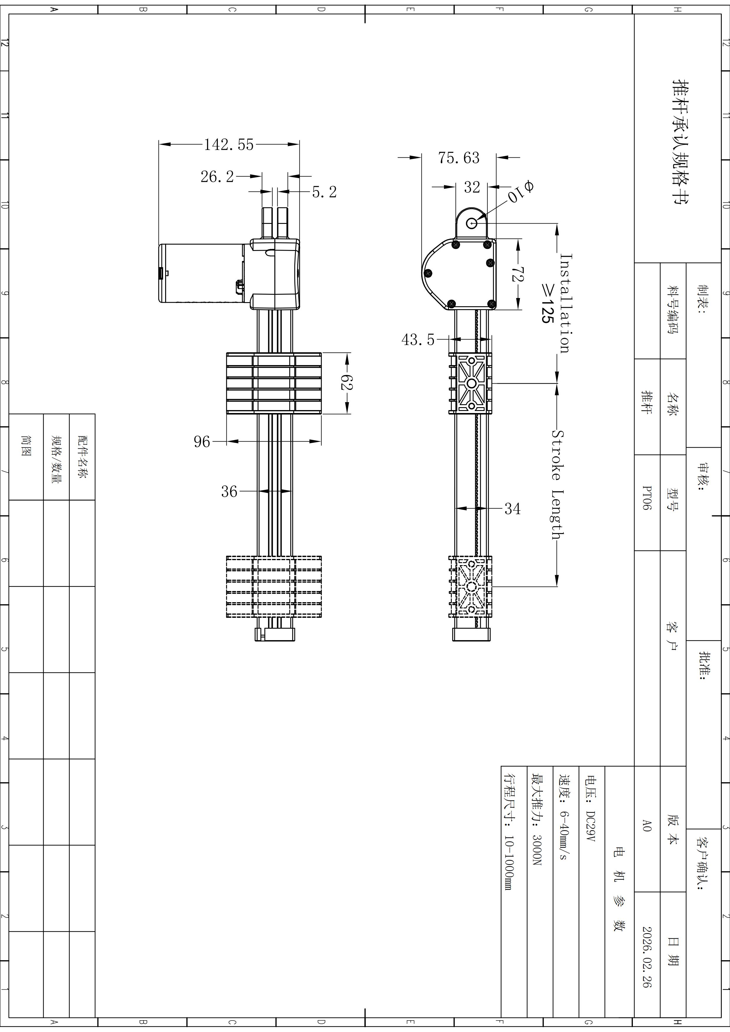
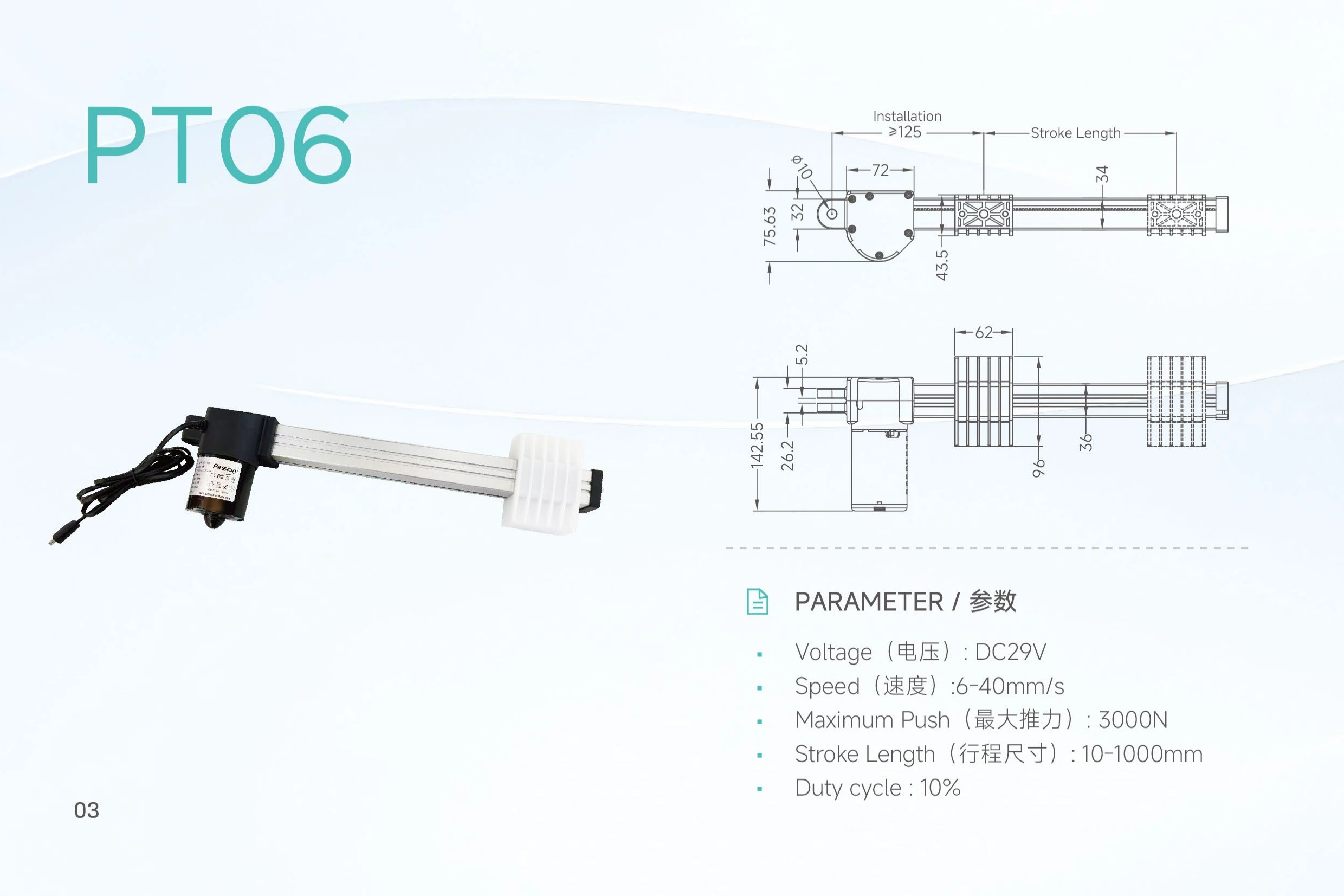
The record lists ≥125 mm installation dimension, 86.5 mm profile height, 42 mm motor width, 30 mm outer tube, 24 mm inner extension tube, Ø10 mm clevis hole and a 19.5 mm base-hole offset.
What does the 10% duty cycle mean in minutes?
The time basis and test conditions are not stated, so provide the real run/rest pattern for review instead of converting the percentage into a fixed schedule.
Are feedback and environmental ratings confirmed?
No model-specific feedback method or environmental protection rating is established in the available ZT17 evidence.