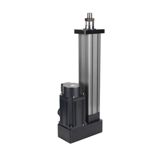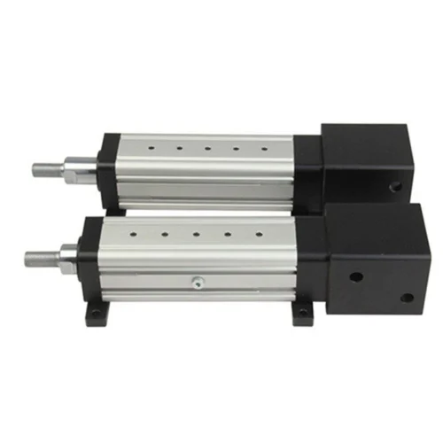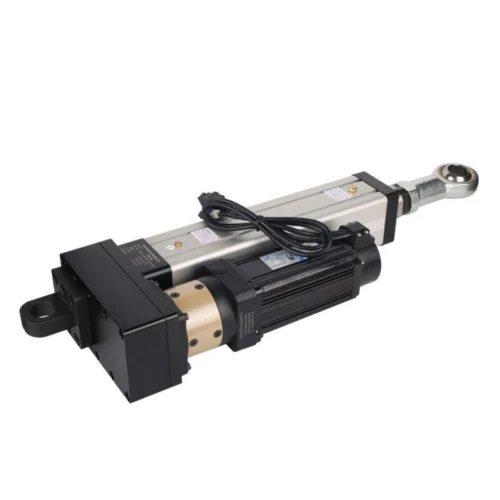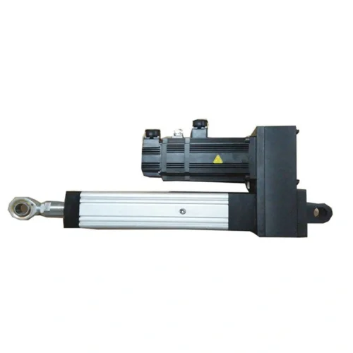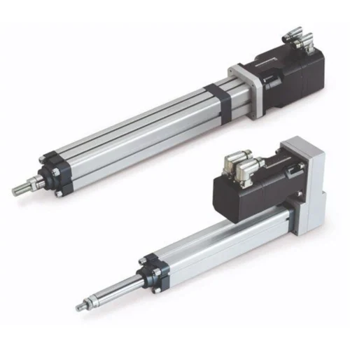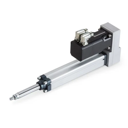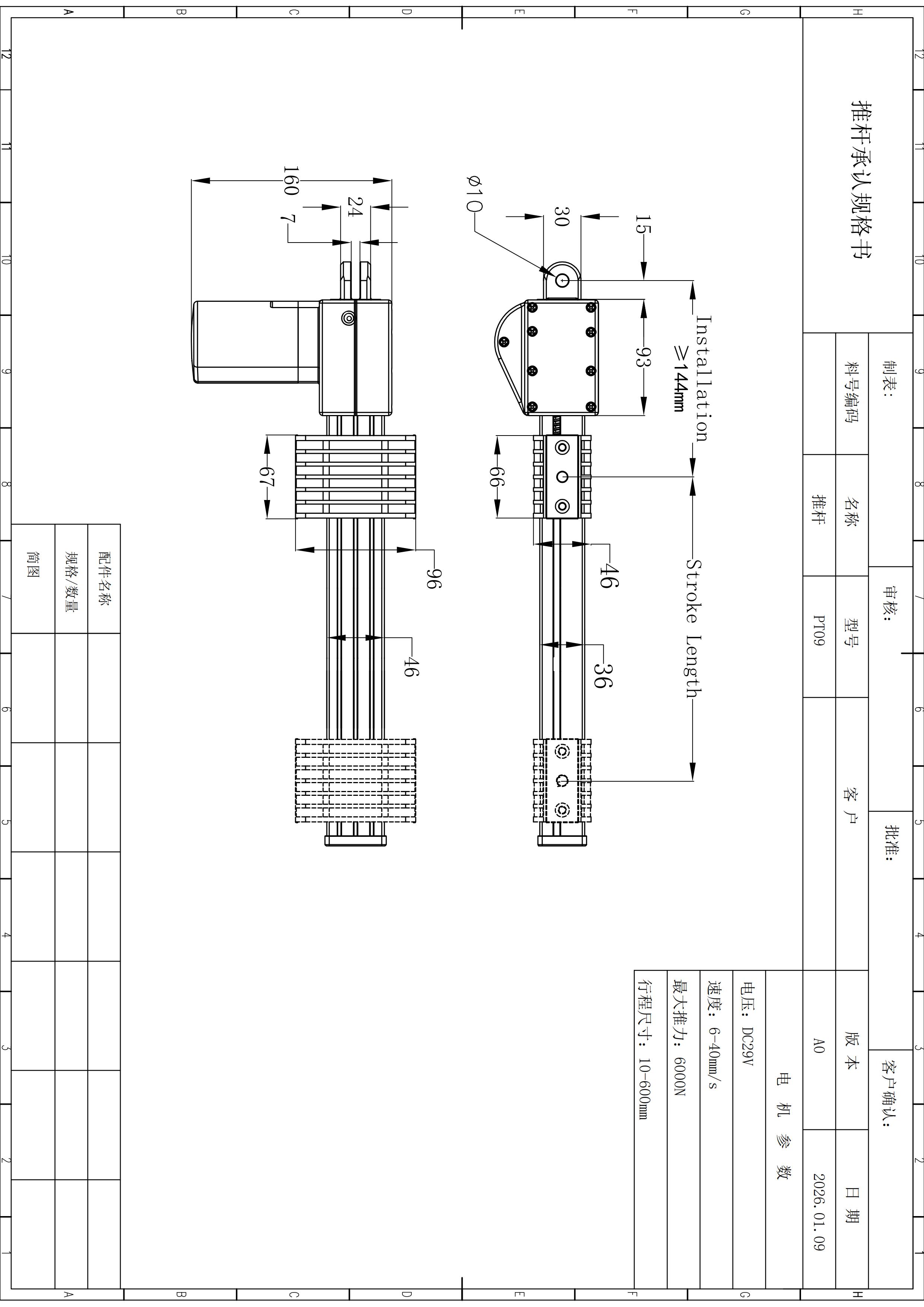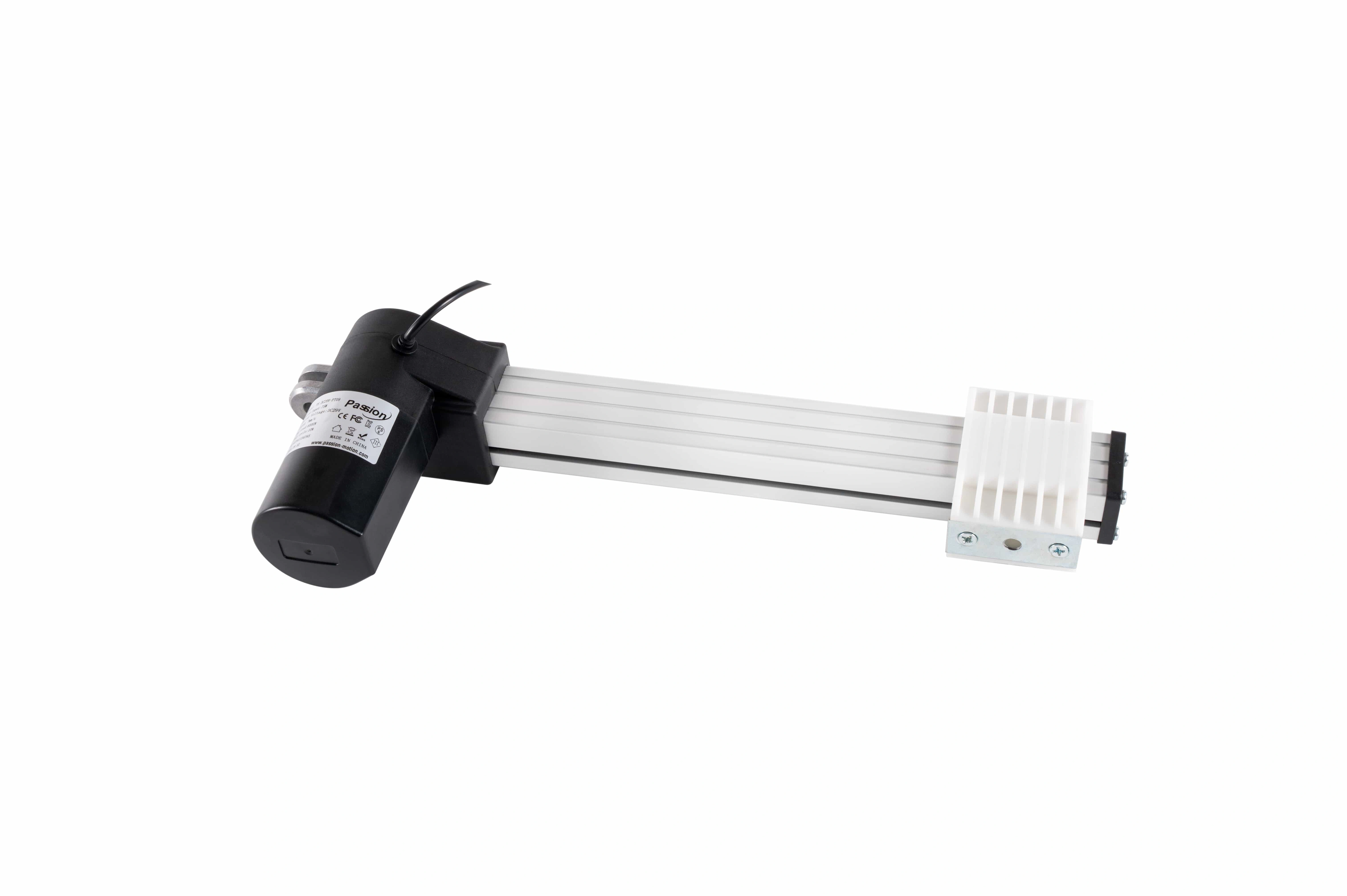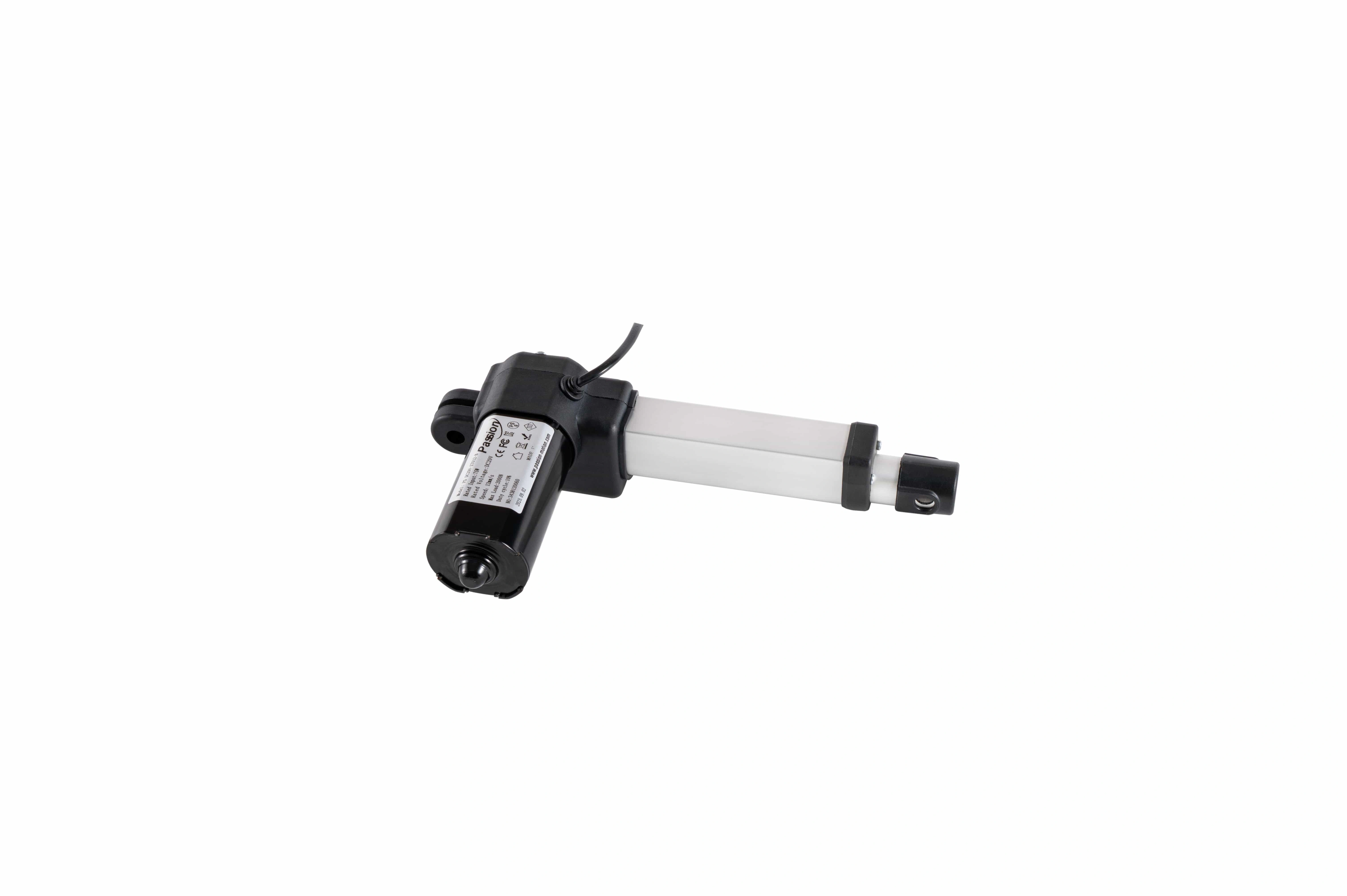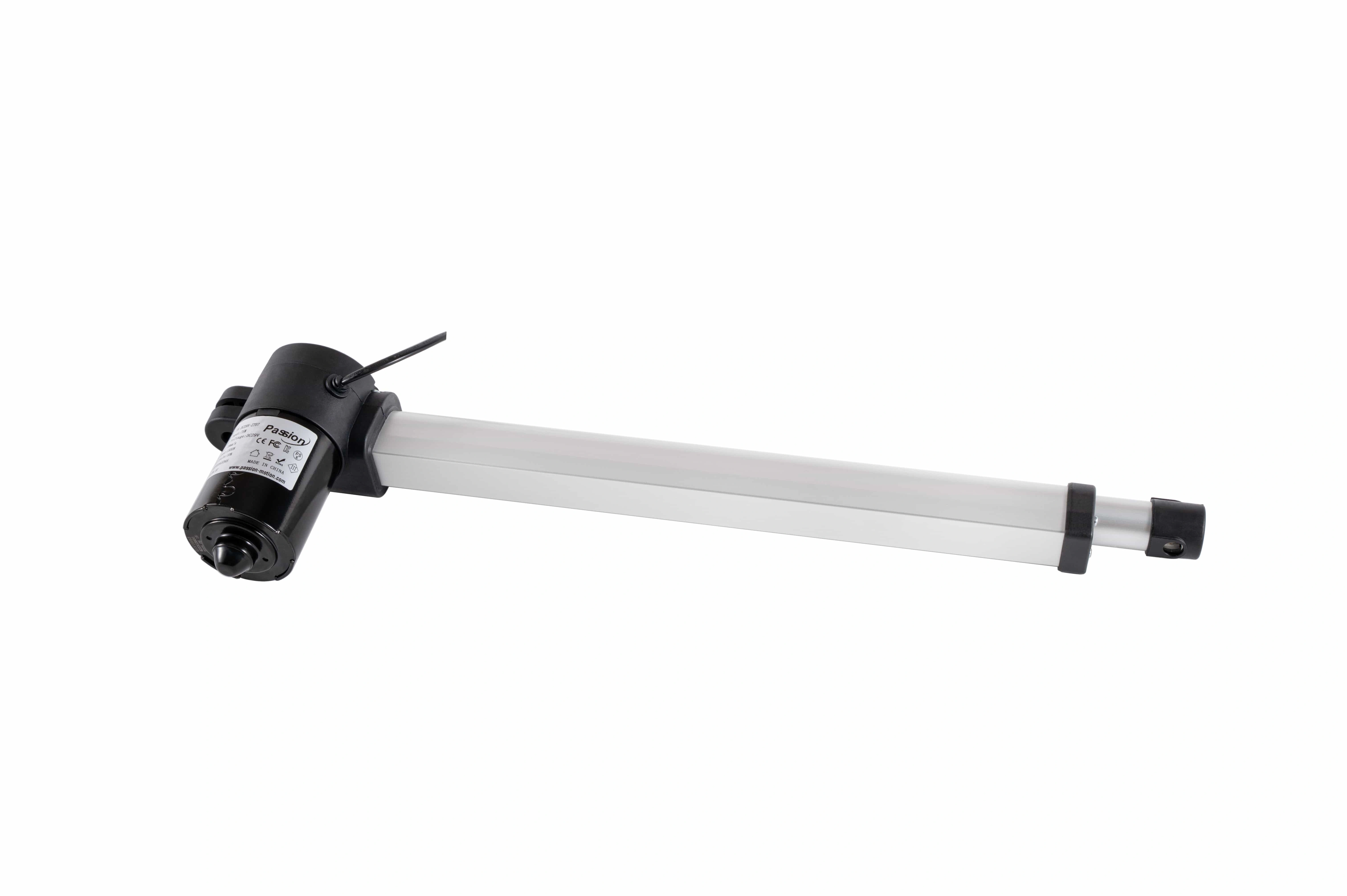
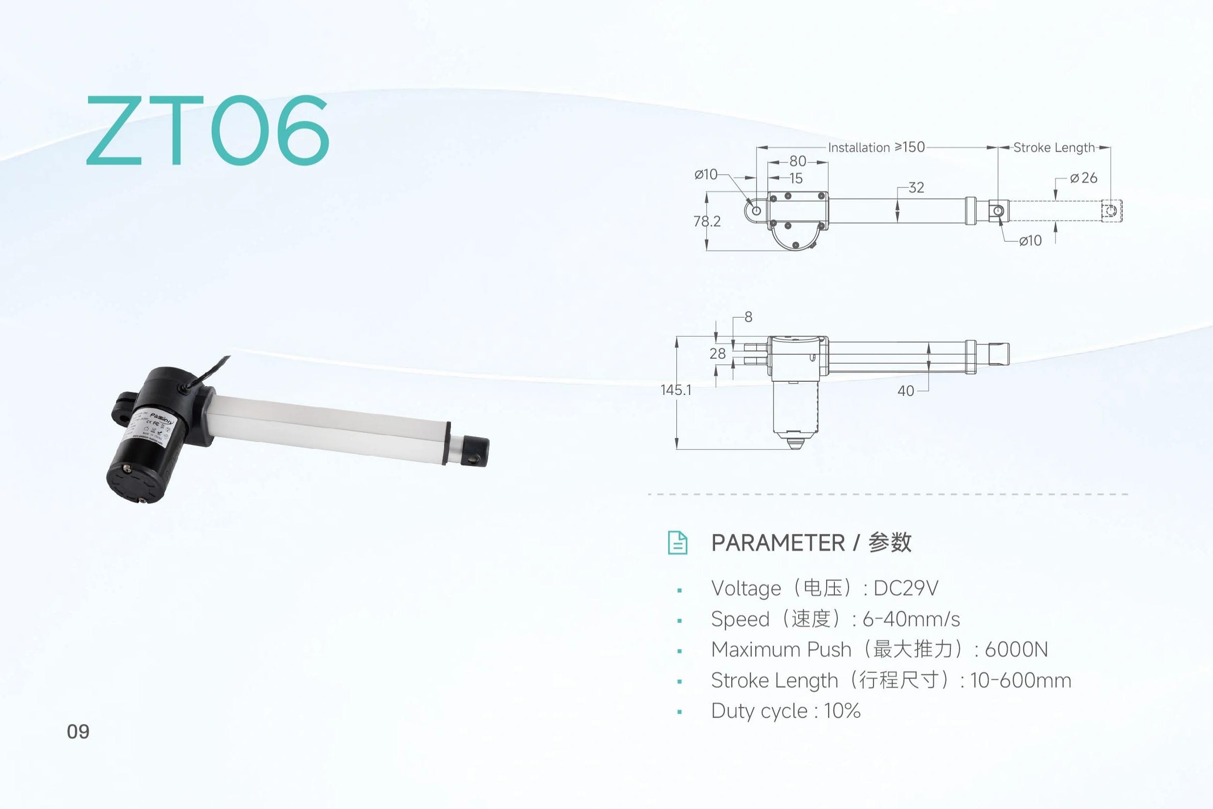
ZT06 Linear Actuator: 6000N, 600mm Stroke
A 29 V push-rod actuator with up to
6,000 N maximum push
, a published
6–40 mm/s
speed range and
10–600 mm
stroke options, plus model-specific tube and mounting dimensions for packaging review. These are configuration limits, not proof that every maximum occurs together.
Start with the working load.
The 6,000 N figure is a maximum push rating. It does not establish 40 mm/s at maximum push.
Keep the published values visible, then check them as one operating point.
ZT06 publishes force, speed, stroke and duty limits independently. The page does not assume maximum push, maximum speed and maximum travel are available together because no force-versus-speed table is present in the locked source.
| Parameter | ZT06 published value | Selection note |
|---|---|---|
| Maximum push | 6,000 N | Maximum push rating; a separate pull-force value is not established in the locked record. |
| Speed | 6–40 mm/s | Published range. State the required loaded speed when requesting configuration review. |
| Stroke | 10–600 mm | Published travel range. Confirm selected travel together with force, speed and installation space. |
| Duty cycle | 10% | The local source provides the percentage but not a detailed test-time basis. |
| Input voltage | DC 29 V | Confirm power, current capacity, connector and control arrangement for the selected configuration. |
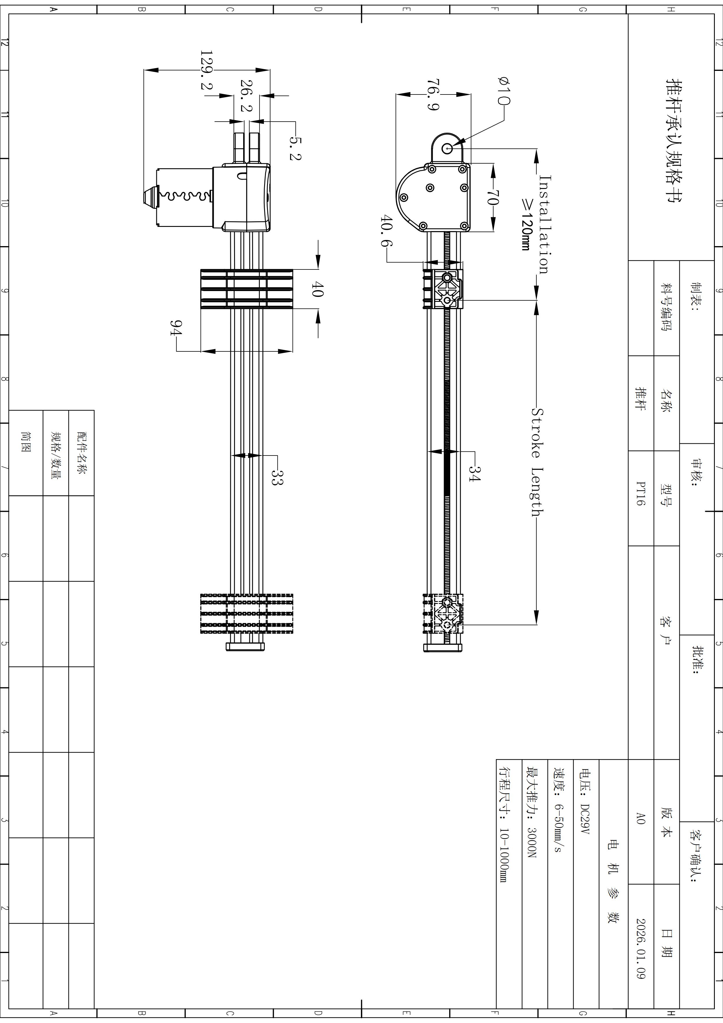
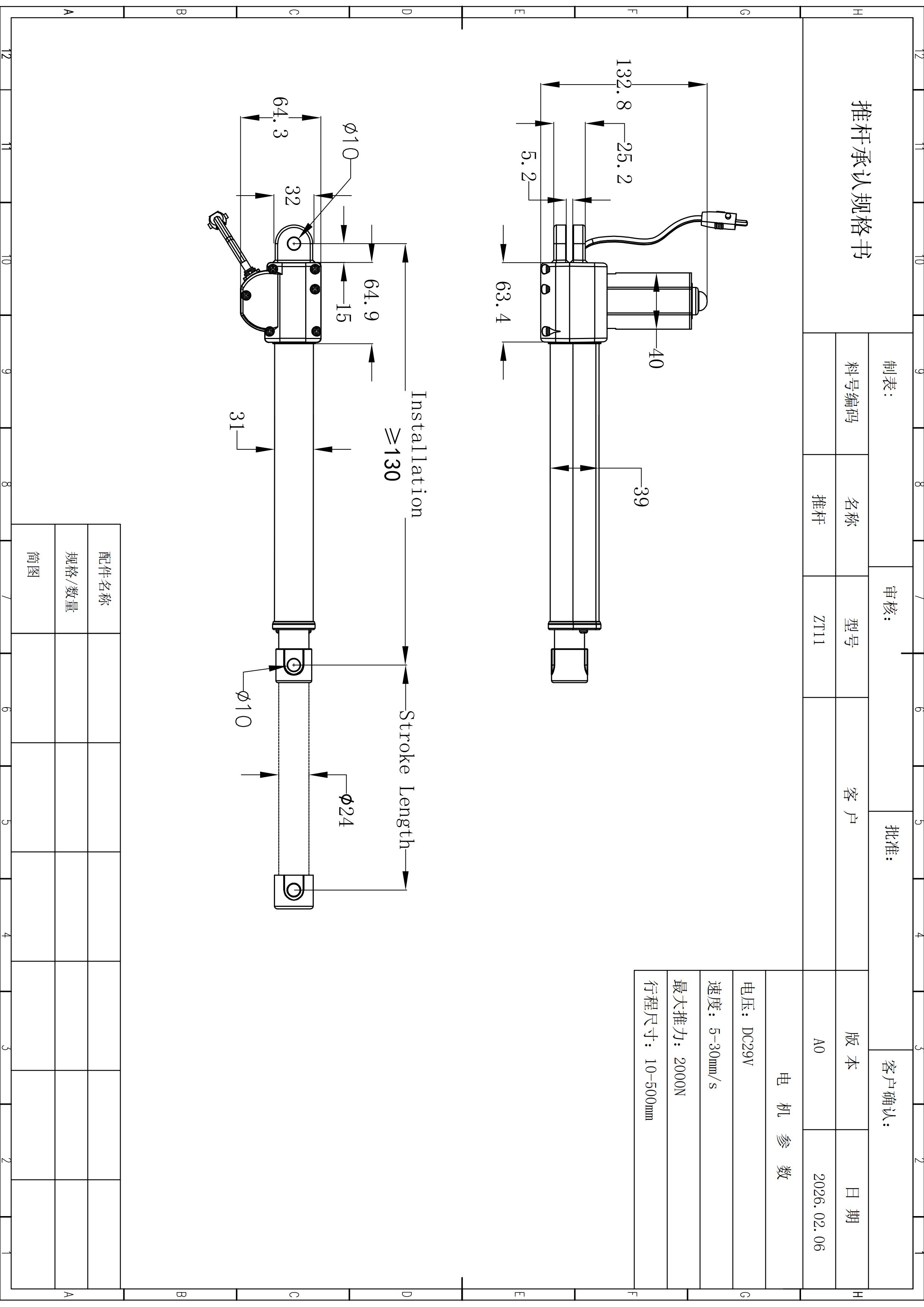
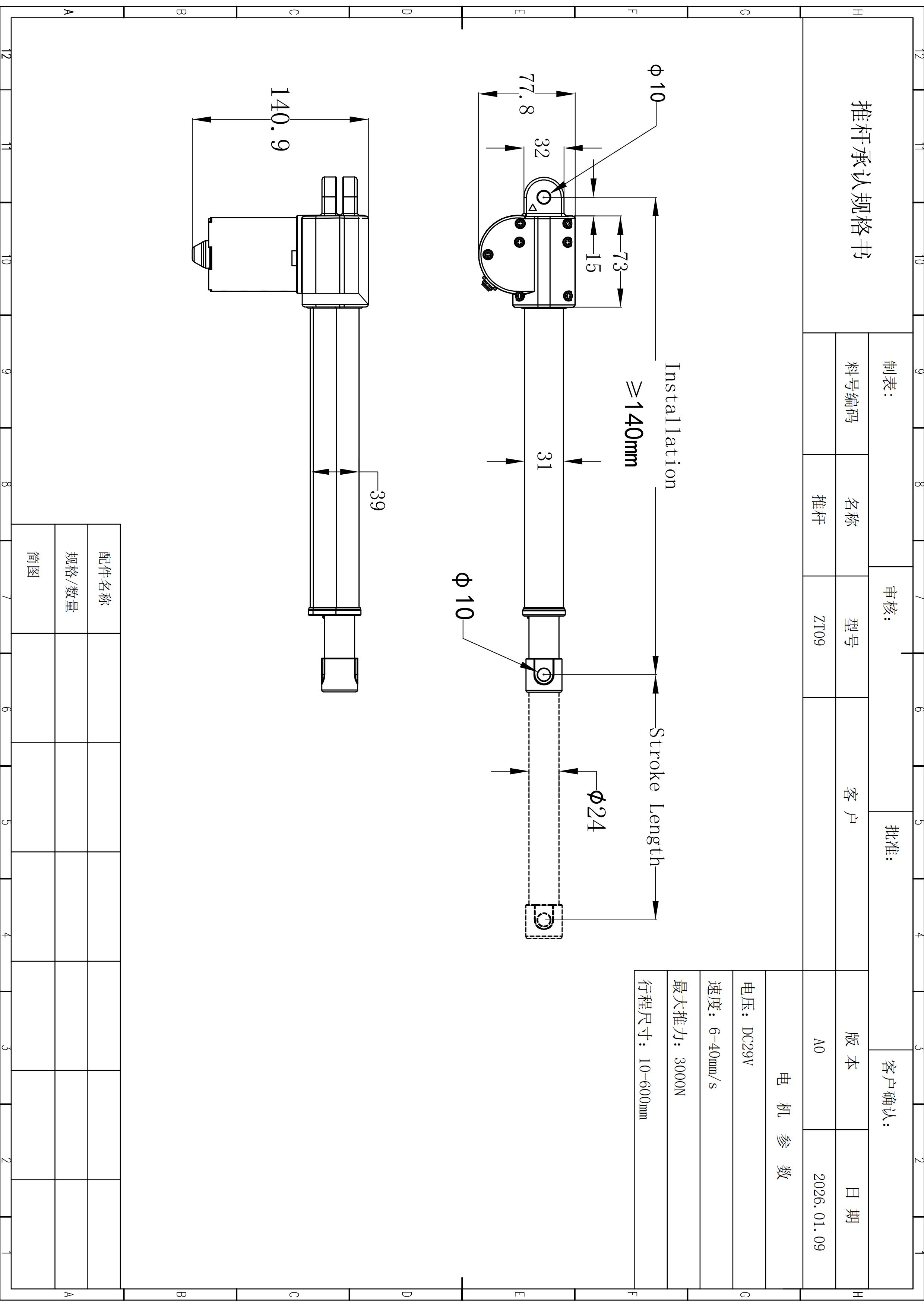
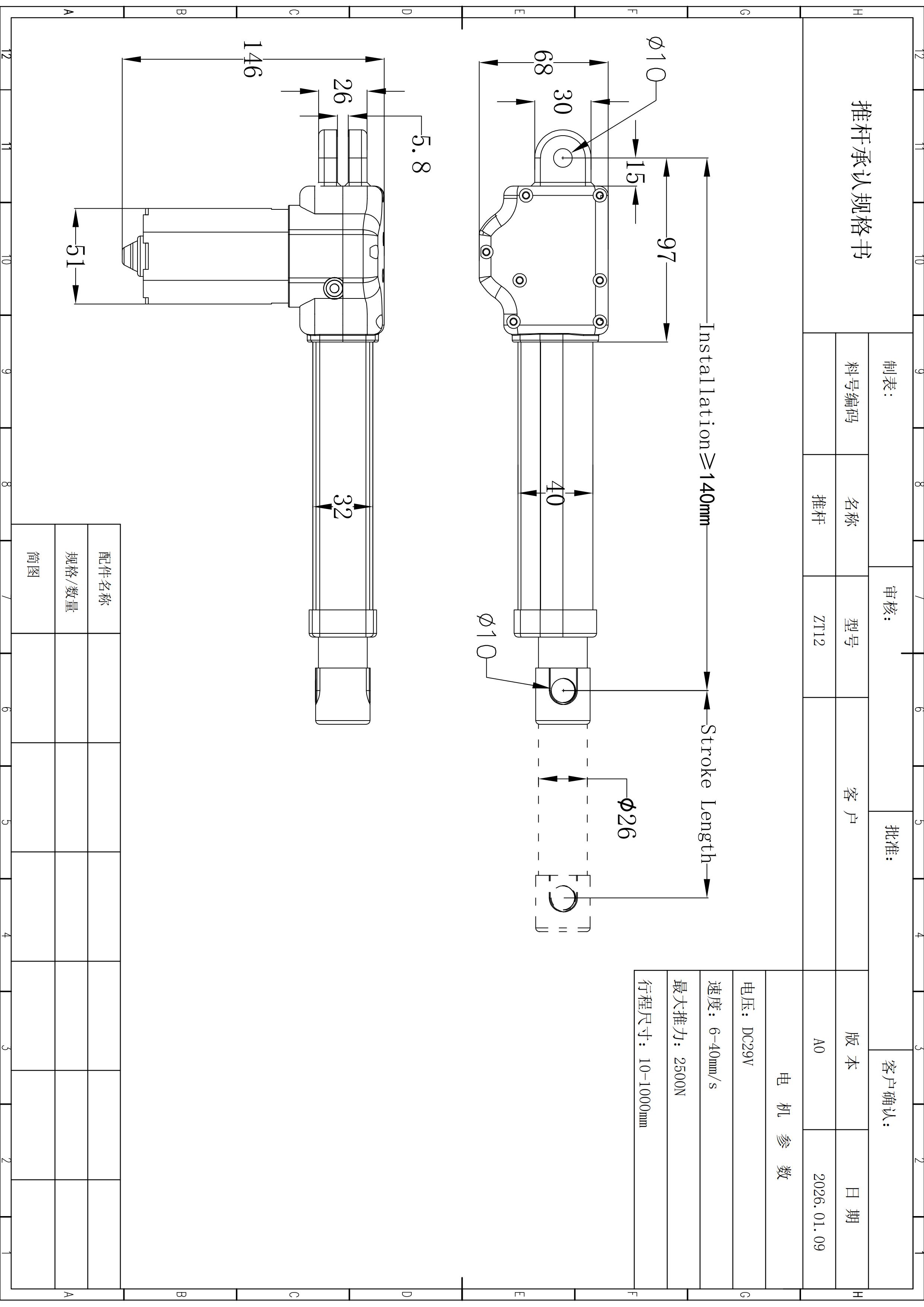
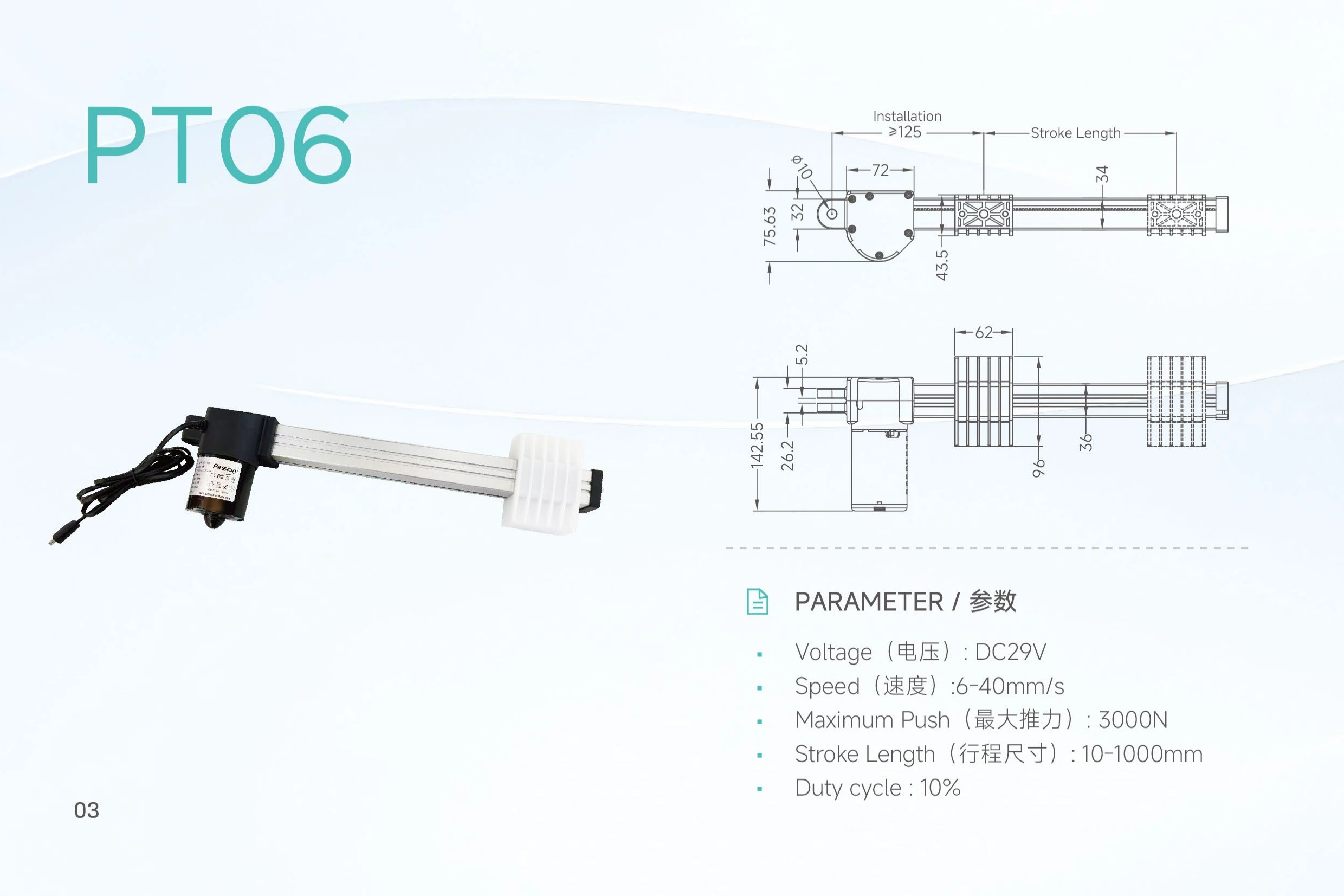
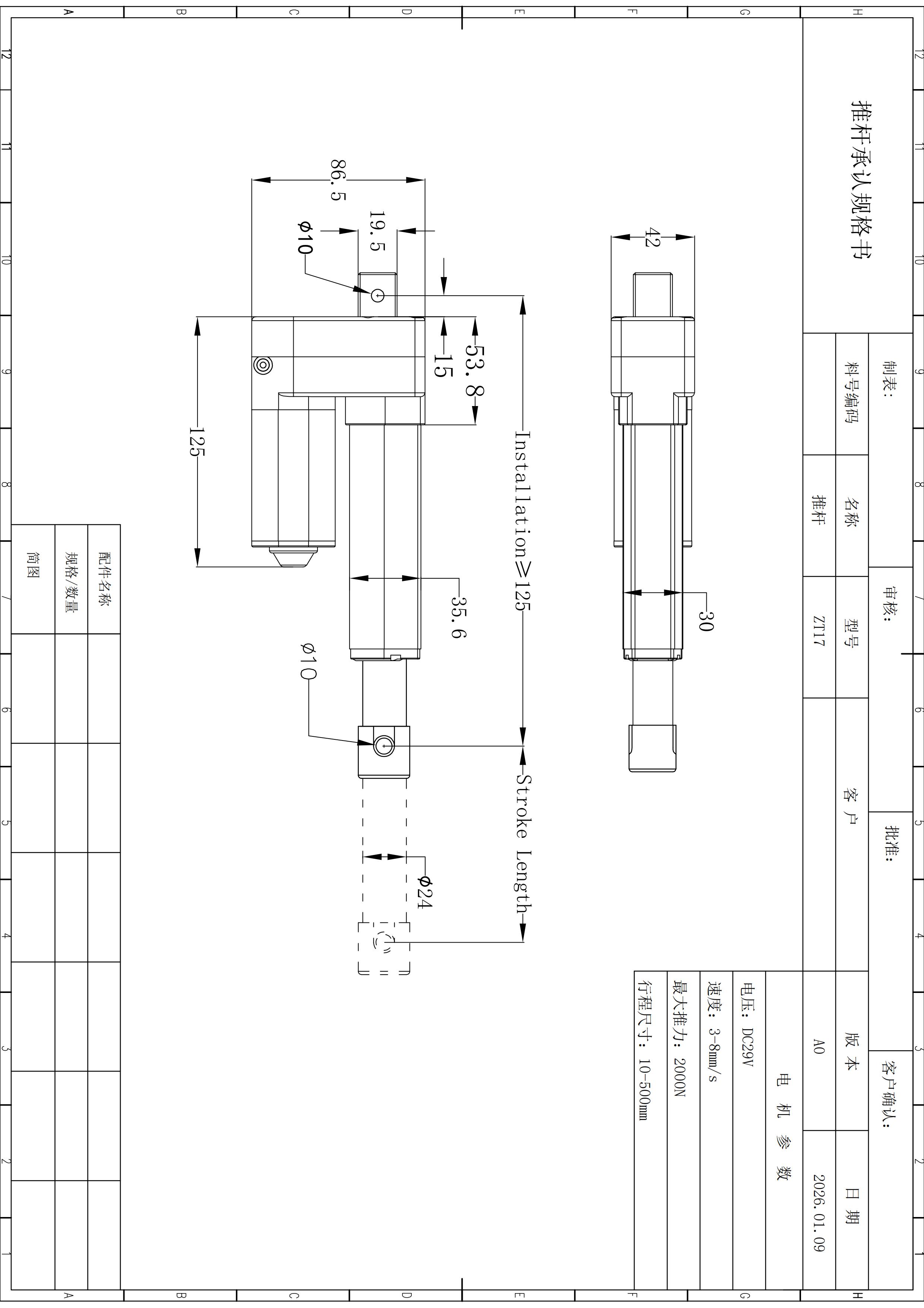
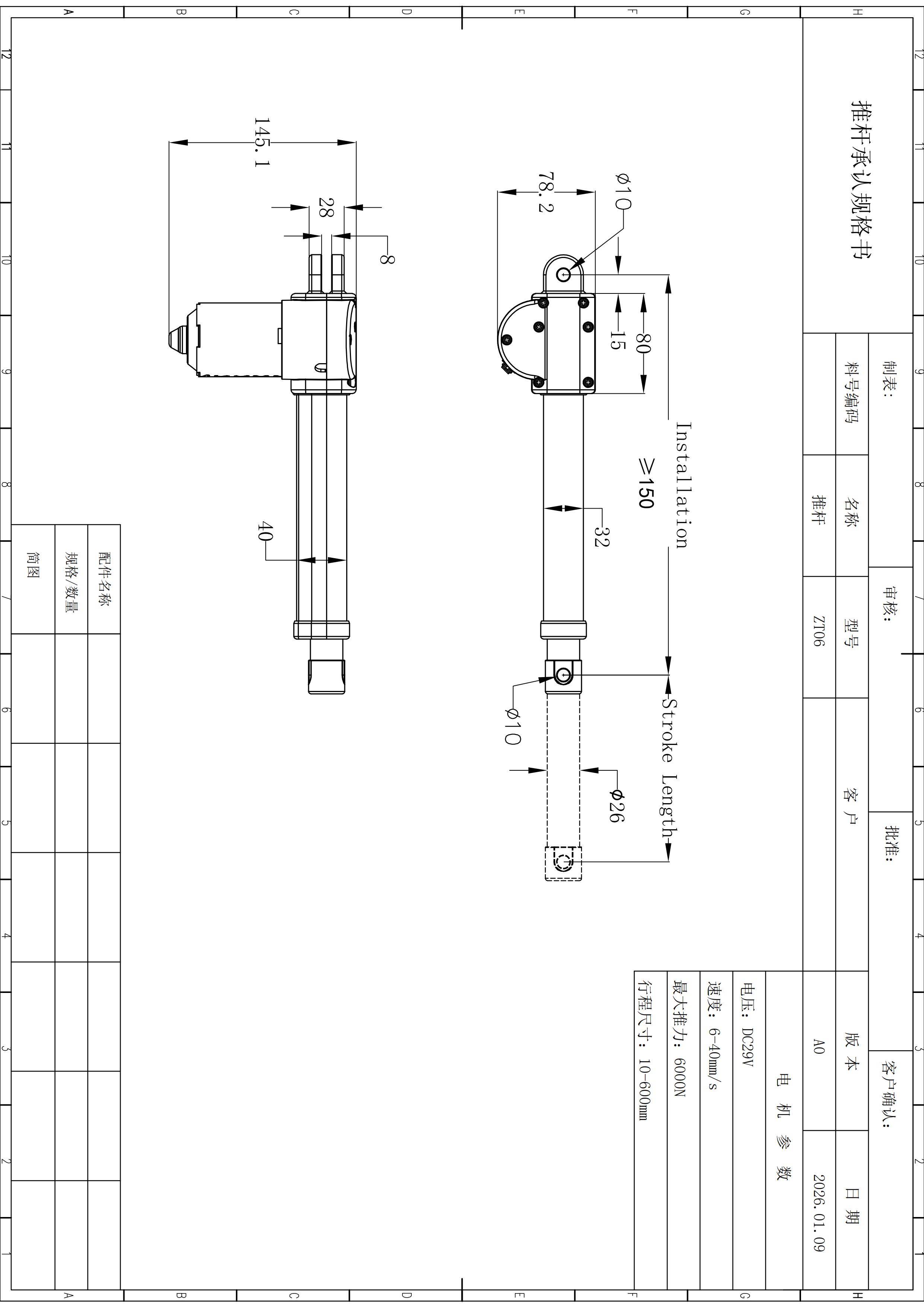
| Minimum installation length | ≥150 mm | Drawing-reference value; do not derive a universal closed-length formula from it. |
| Mounting pin holes | Ø10 mm, both ends | Use the current drawing for final mounting release. |
| Inner tube outer diameter | Ø26 mm | Drawing-reference value. |
| Outer tube width | 32 mm | Drawing-reference value. |
| Motor width | 40 mm | Drawing-reference value. |
| Motor assembly height | 145.1 mm | Drawing-reference value. |
| Front bracket height | 78.2 mm | Drawing-reference value. |
| Pin-hole center-to-edge offsets | 15 / 80 / 28 / 8 mm | Recorded drawing-reference offsets. Do not reconstruct final geometry from isolated values. |
Read the ZT06 package as a set of mounting constraints.
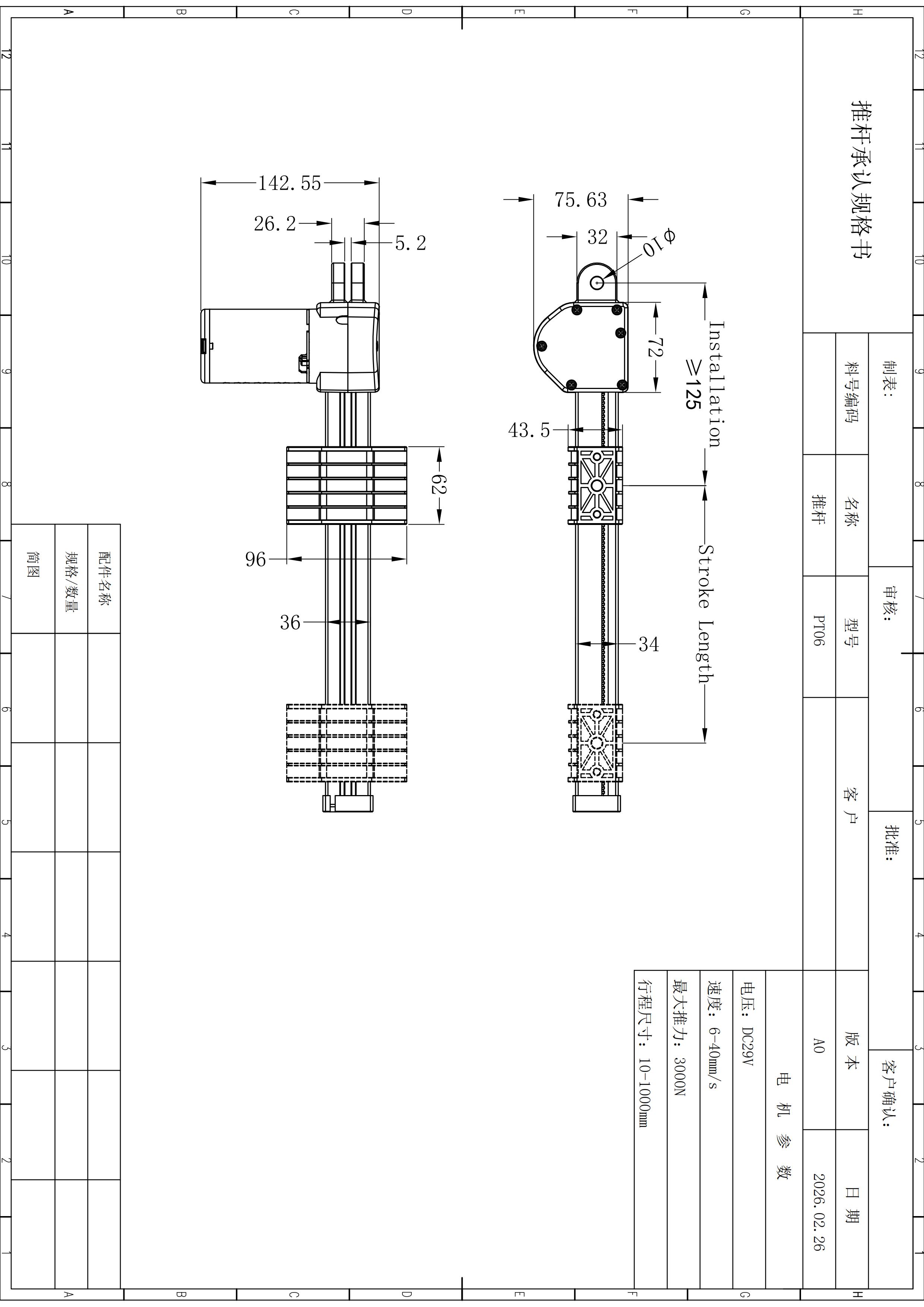
The interface below highlights verified drawing-reference dimensions one at a time. It is illustrative and not to scale; use the current technical drawing for final mechanical release.
Send the actual operating point, not four independent maximums.
A useful ZT06 review starts with working load and motion direction, then adds loaded speed, travel, mounting space, duty pattern, environment, control, electrical interface and documentation requirements.
Needs confirmation before release
Specific loaded speed near maximum push, proof of a long-stroke force/speed combination, pull force, defined ingress protection, feedback device, positioning accuracy, control-box pairing, life-cycle data and model-specific compliance evidence are not established in the locked ZT06 source.
Define the ZT06 requirement in one line.
Send working load + load direction + required loaded speed + stroke + installation space + duty pattern + control / power needs + quantity . The configuration can then be checked as one operating point instead of combining unrelated endpoints.
Use the published limits as boundaries, not shortcuts.
The verified local record supports DC 29 V, 6,000 N maximum push, 6–40 mm/s published speed, 10–600 mm stroke and a 10% duty-cycle figure.
Is ZT06 rated for 6,000 N?
Yes. The local ZT06 product data lists 6,000 N as the maximum push rating. A separate pull-force value is not published in the locked source.
Can ZT06 run at 40 mm/s while pushing 6,000 N?
The available data does not establish that operating point. It lists the force maximum and speed range separately and provides no force-speed pairing table.
Is the full 600 mm stroke available with every speed and force option?
The source confirms a 10–600 mm stroke range but does not prove every stroke, force and speed endpoint can be combined.
What voltage does ZT06 use?
The locked product source specifies DC 29 V.
What mounting dimensions are documented?
The local record includes a minimum installation length of at least 150 mm, Ø10 mm pin holes at both ends, Ø26 mm inner-tube outer diameter, 32 mm outer-tube width, 40 mm motor width, 145.1 mm motor-assembly height, 78.2 mm front-bracket height, and 15 / 80 / 28 / 8 mm recorded pin-hole center-to-edge offsets. Use the current technical drawing for final release.
What should I send for a quote?
Send the working load, direction, loaded speed, stroke, installation space, duty pattern, environment, control/electrical requirements, documentation needs and quantity.