When engineers compare 12V vs 24V vs 29V linear actuators, the most important point is that voltage is a system architecture choice, not a shortcut for predicting force or speed.
The selected DC bus has to match the motor winding, control electronics, power source, connectors, wiring, protection devices, and operating current. A mechanically suitable motion component can still be unusable if its electrical architecture does not match the rest of the system.
For OEM projects, choose voltage by answering four questions:
- What DC bus is already available?
- How much current will the system draw at the required load?
- How long are the cables, and what voltage drop is acceptable?
- Are the motor, controller, supply, connectors, and protection devices all designed for the same voltage class?
12V vs 24V vs 29V comparison table
| Engineering factor | 12V system | 24V system | 29V system |
|---|---|---|---|
| Razón típica para considerarlo. | native 12V battery/vehicle bus, compact low-voltage architecture | lower current than 12V at equal power, common industrial/control ecosystem | matched furniture/motion ecosystem where controller and supply are explicitly designed around 29V |
| Current at equal electrical power | highest of the three | about half of 12V | lower than 24V for the same power |
| Cable voltage-drop sensitivity | highest percentage impact for the same absolute drop | lower percentage impact than 12V | lower again at equal power/current conditions |
| Wire/connector current burden | highest at equal power | más bajo | lower at equal power |
| Native-bus advantage | useful when the machine already has 12V DC | useful when the machine/control platform already has 24V DC | useful only when the motion ecosystem is intentionally designed around 29V |
| Interchangeability | not interchangeable with higher-voltage devices unless rated | not automatically compatible with 12V or 29V devices | not a drop-in replacement for nominal 24V hardware |
| Supply sizing | check startup, running, stall, and simultaneous loads | same | same |
| Controller requirement | controller must support the motor and 12V bus | controller must support the motor and 24V bus | controller must explicitly support the intended 29V system |
| Best decision basis | total system compatibility | total system compatibility | total system compatibility |
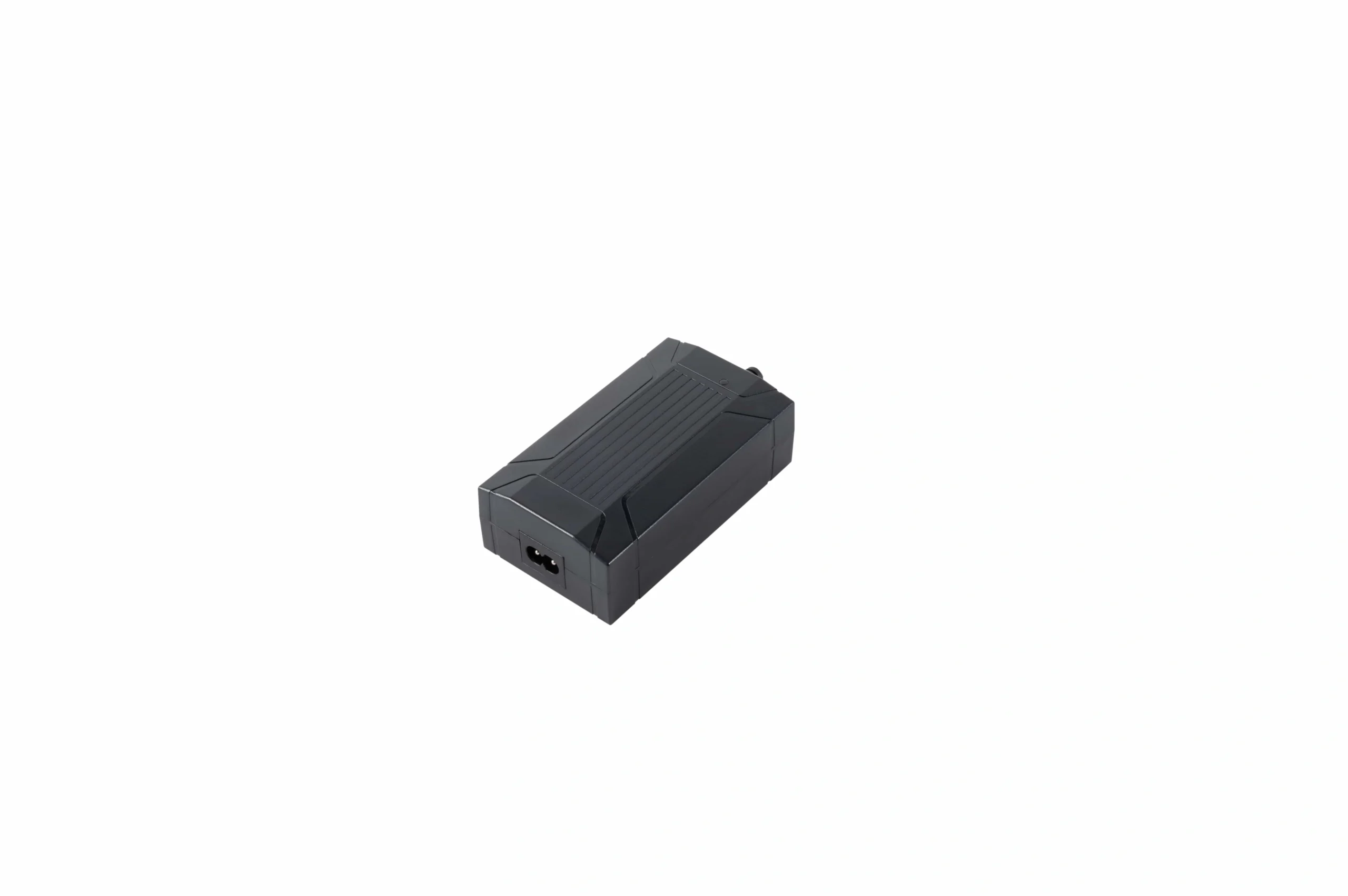
Voltage choice is a system decision: the supply, controller, motor, connectors, and wiring must be specified as one compatible electrical architecture.
The table compares system implications. It does not imply that ServoCylMotion offers product families at every voltage.
Voltage does not determine force or speed by itself
It is tempting to assume that a 24V actuator must be stronger or faster than a 12V version.
That conclusion is not valid without the full design.
Force and speed depend on:
- motor winding;
- motor size;
- relación de transmisión;
- avance del tornillo;
- transmission efficiency;
- controller current limit;
- supply current capability;
- load point;
- ciclo de trabajo;
- mechanical design.
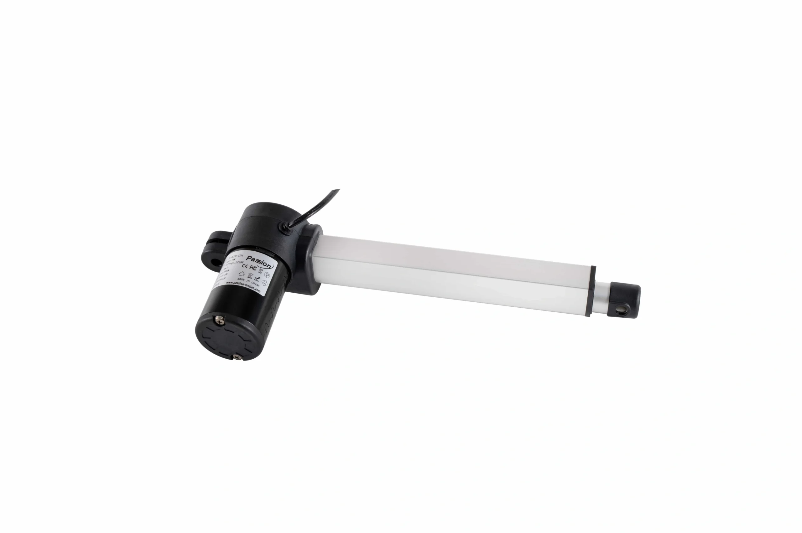
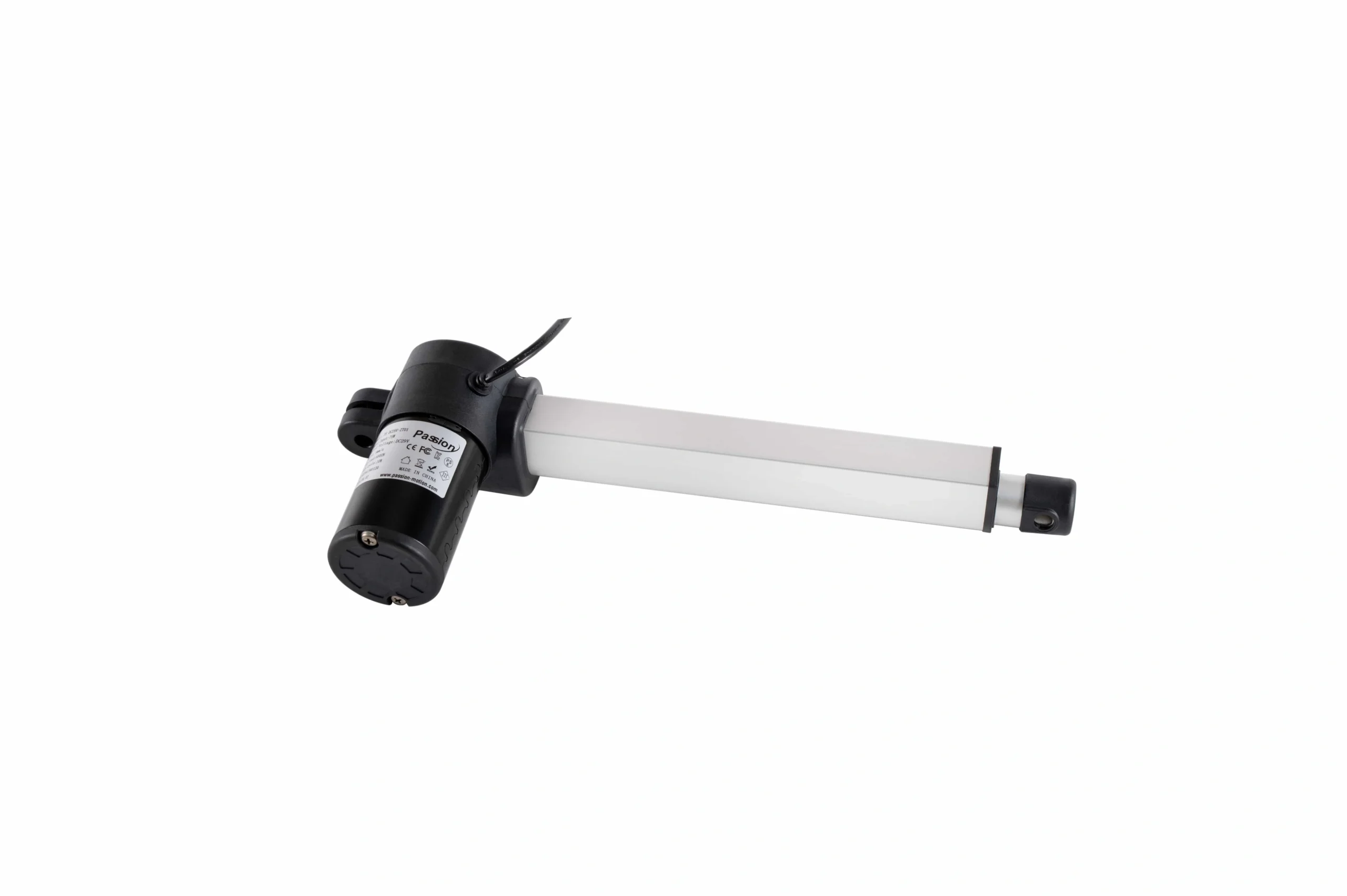
A voltage label alone does not define force or speed; the motor, gearing, controller, load, and rated operating point still govern performance.
A well-designed 12V system can outperform a poorly matched 24V system in a particular application. Likewise, a 29V label alone says nothing about whether a device is suitable for a specific load.
Compare rated force-speed-current data at the intended operating point, not voltage in isolation.
The basic electrical relationship: P = V × I
For DC power:
Power (W) = Voltage (V) × Current (A)
Current (A) = Power (W) / Voltage (V)
This relationship explains one of the main system-level differences between voltage classes.
Worked example: equal 120 W electrical power
If three idealized systems each deliver 120 W of electrical input power:
| Voltaje | Ideal current at 120 W |
|---|---|
| 12 V | 10.0 A |
| 24 V | 5.0 A |
| 29 V | 4.14 A |
This is not an actuator performance prediction. It is an electrical comparison only.
Real current depends on motor efficiency, controller losses, load, speed, acceleration, friction, and the actual drive design.
The key takeaway is that for the same electrical power, higher voltage means lower current.
Why current matters to the wiring
Current affects more than the power-supply label.
It affects:
- tamaño del conductor;
- calificación del conector;
- relay or MOSFET current;
- fuse size;
- harness temperature;
- caída de voltaje;
- contact heating.
Resistive cable loss follows:
Cable loss = I² × R
If current doubles through the same resistance, resistive loss increases by four times.
That is one reason higher-voltage architectures can be attractive for longer cable runs or higher-power systems.
But the conclusion has an important boundary:
You cannot raise voltage merely to reduce current unless the motor, controller, supply, protection, and connected electronics are designed for that voltage.
Voltage drop is a percentage problem
Suppose the wiring loses 1 V between the supply and the controller.
That represents:
- 8.3% of a 12V bus;
- 4.2% of a 24V bus;
- 3.4% of a 29V bus.
The same absolute loss therefore consumes a larger fraction of the available voltage in a lower-voltage system.
Voltage drop can affect:
- velocidad del motor;
- available torque;
- controller undervoltage behavior;
- startup reliability;
- multi-motor synchronization;
- fault resets.
For long cable runs, verify:
- calibre de cable;
- total loop length;
- maximum current;
- connector resistance;
- expected voltage at the controller under load.
Startup and stall current can dominate supply sizing
The current printed beside a nominal operating condition may not be the worst case.
A DC motor can draw substantially more current during:
- arranque;
- hard acceleration;
- high-load movement;
- atasco;
- obstrucción;
- direction reversal.
A supply that works during no-load testing may sag or enter protection when the real mechanism starts under load.
For each motor channel, freeze:
- no-load current;
- expected loaded current;
- corriente de arranque/pico;
- stall current or controller current limit;
- permitted duration;
- ciclo de trabajo.
For multiple motors, also define which axes are allowed to start or move simultaneously.
Multi-motor systems need a total current budget
A two-motor system is not sized by simply checking one motor twice.
The controller may:
- start both motors together;
- start them sequentially;
- limit each channel;
- limit total current;
- stop both if one faults;
- compensate for position mismatch.
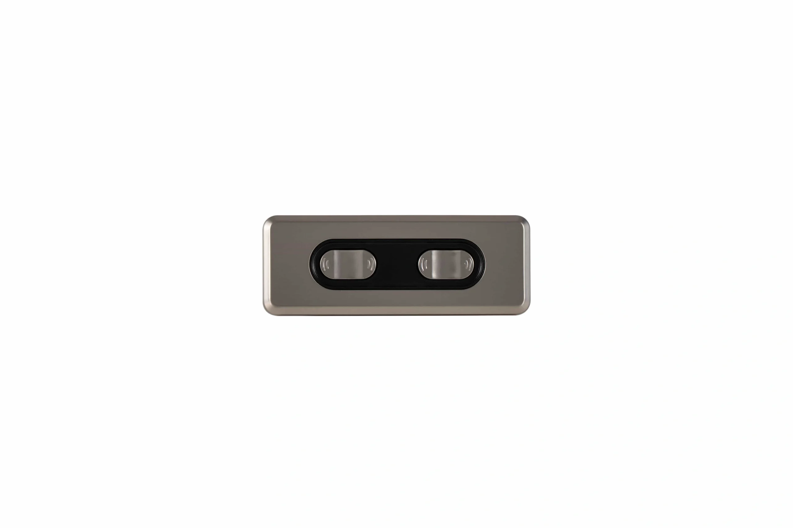
Multi-motor systems must budget simultaneous current and confirm controller channel ratings, connector limits, and supply capacity.
The supply and harness should therefore be checked against the worst permitted operating state, including simultaneous startup if the controller allows it.
A useful system current table is:
| Artículo | Running current | Startup/peak current | Simultaneous? |
|---|---|---|---|
| Motor 1 | project value | project value | yes/no |
| Motor 2 | project value | project value | yes/no |
| Controller electronics | project value | project value | always |
| Accesorios | project value | project value | depends |
| Margen de diseño | project rule | — | — |
Do not populate these values from a neighboring model. Use the actual project data.
Why 12V can make sense
A 12V architecture can be practical when the machine already has a native 12V source, such as:
- vehicle electrical systems;
- battery-powered equipment;
- compact mobile devices;
- legacy low-voltage platforms.
The advantage is often architectural simplicity: fewer conversion stages and direct use of the native bus.
The tradeoff is higher current for a given power level, which can increase:
- cable size;
- connector current requirements;
- voltage-drop sensitivity;
- fuse/current-limit requirements.
For a new design with no native bus constraint, compare the total wiring and control architecture before committing.
Why 24V can make sense
24V is widely used in industrial control environments, which can simplify integration when the rest of the machine already uses a compatible 24V DC bus.
At equal electrical power compared with 12V, current is lower.
That can help with:
- long harnesses;
- connector loading;
- caída de voltaje;
- distribution losses.
However, a 24V controller cannot be assumed compatible with every 24V motor, and a nominal 24V motor cannot automatically accept a different supply voltage.
The complete input range and current requirements still have to be verified.
Why 29V appears in actuator ecosystems
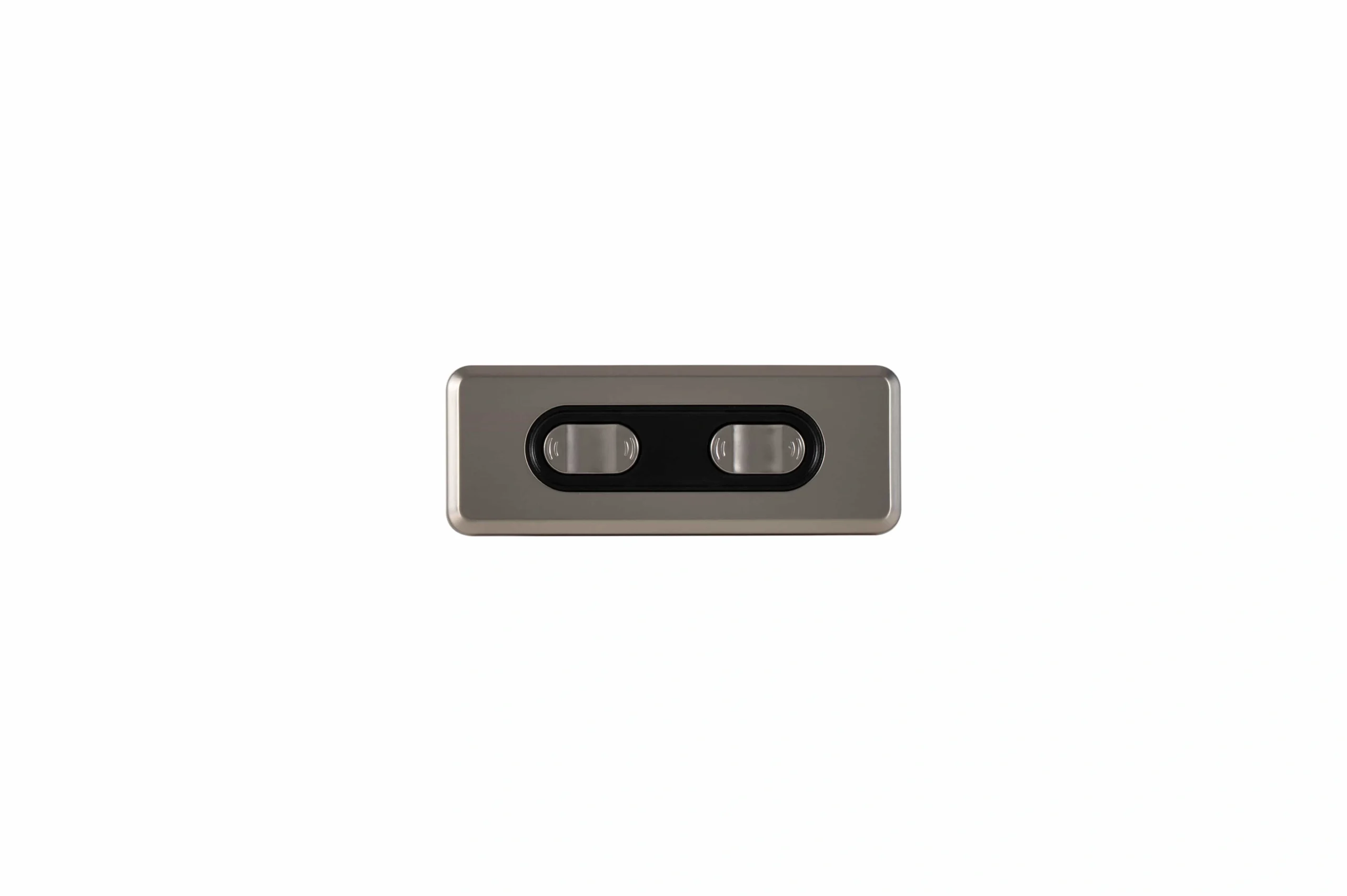
29V often appears in furniture and low-voltage motion ecosystems that use a dedicated AC/DC adapter, control box, handset, and one or more motors as a matched system.
La palabra importante es matched.
A 29V supply should not be treated as a universal replacement for a nominal 24V supply.
Verificar:
- controller input range;
- motor rated voltage;
- protection thresholds;
- conector/pinout;
- interfaz de retroalimentación;
- supply current;
- firmware/configuration;
- allowed accessories.
ServoCylMotion has a documented 29V accessory ecosystem at the project level, but model-specific combinations still need compatibility verification.
Utilice el recurso de compatibilidad del sistema before freezing a controller-supply-motor combination.
Do not overvoltage a nominal device by assumption
A common mistake is reasoning:
29V is close to 24V, so it should be fine.
That is not an engineering specification.
A device may have:
- a narrow input range;
- controller overvoltage protection;
- motor heating limits;
- speed limits;
- relay/MOSFET voltage limits;
- accessory limits.
Only the documented input range or approved system combination establishes compatibility.
Likewise, running a motor below its intended voltage can change speed, available torque, current behavior, and controller response.
Native bus vs dedicated adapter architecture
Voltage selection often follows one of two architectures.
Native DC bus
The actuator system uses the machine’s existing battery or DC supply.
Ventajas:
– fewer conversion stages;
– simpler power distribution;
– shared protection architecture.
Questions:
– is voltage stable across all operating conditions?
– what happens during engine charging or battery discharge?
– can the bus supply startup current?
– is noise/transient protection adequate?
Dedicated AC/DC adapter
El sistema de movimiento tiene su propio suministro.
Ventajas:
– voltaje de salida controlado;
– aislamiento de subsistemas más fácil;
– calificación más simple de un ecosistema correspondiente.
Questions:
– ¿es suficiente la capacidad de corriente?
– ¿qué modos de protección existen?
– ¿qué conector se utiliza?
– ¿el adaptador se recupera correctamente después de una sobrecarga?
– ¿el cable de CA regional está separado de la definición del sistema de CC?
Las preguntas sobre el enchufe regional pertenecen a la guía de estándares de enchufe separada en lugar de esta comparación de voltaje.
Congela el BOM como una matriz de compatibilidad
Antes del lanzamiento, crea una tabla de compatibilidad.
| Elemento BOM | Campo requerido |
|---|---|
| Motor / componente de movimiento | rango de voltaje nominal, corriente en funcionamiento/pico, retroalimentación |
| Controlador | rango de voltaje de entrada, corriente del canal, corriente total, tipo de retroalimentación |
| suministro de CC | voltaje de salida, corriente continua/pico, comportamiento de protección |
| Arnés | calibre de cable, longitud, conector, pinout |
| cable de entrada de CA | formato de enchufe regional, clasificación de corriente/voltaje |
| Fusible/protección | clasificación y coordinación |
| Firmware/configuración | revisión aprobada |
| Lógica de múltiples motores | operación simultánea y límites de corriente |
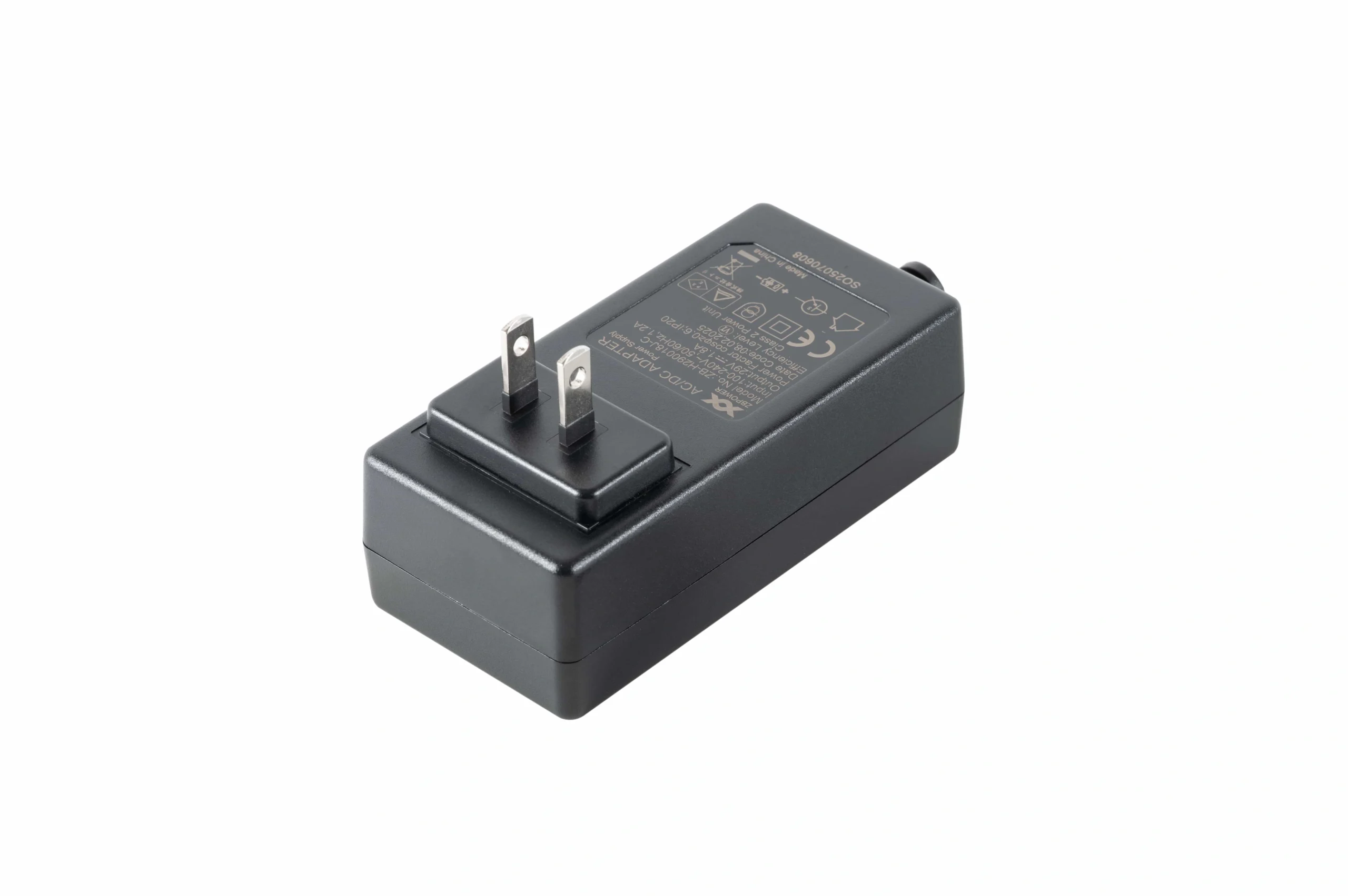
Antes de congelar un suministro, verifica el rango de salida, capacidad de corriente, conector/pinout, comportamiento de protección y compatibilidad con el sistema de control.
Un suministro que se conecta físicamente a un controlador no es automáticamente compatible eléctricamente.
Para opciones de suministro de ServoCylMotion documentadas, utiliza el familia de fuentes de 29V solo después de que se conozcan las condiciones de salida y compatibilidad requeridas.
Lista de verificación de validación
Antes del lanzamiento de producción, prueba la configuración eléctrica completa.
Voltaje
- tensión de suministro sin carga;
- voltaje bajo carga máxima;
- condiciones de entrada de línea baja y línea alta;
- comportamiento de subvoltaje/sobrevoltaje del controlador.
Corriente
- corriente de arranque;
- corriente en funcionamiento cargada;
- corriente de motor simultánea;
- comportamiento de bloqueo/obstrucción;
- respuesta al límite de corriente.
Cableado
- voltaje en el motor más lejano;
- temperatura del conector;
- temperatura del cable;
- caída de voltaje;
- caída de retorno a tierra.
Controles
- inversión de dirección;
- límites finales;
- retroalimentación;
- sincronización en múltiples ejes;
- recuperación de fallos;
- comportamiento de reinicio.
Térmico
- ciclo de trabajo representativo;
- temperatura de suministro;
- temperatura del controlador;
- temperatura del conector/arnés.
Registre la revisión exacta del suministro, controlador, motor, arnés, firmware y parámetros utilizados en la validación.
Regla de selección rápida
Elija 12V cuando un bus nativo de 12V compatible y la arquitectura del sistema lo hagan la mejor opción.
Elija 24V cuando la máquina esté construida en torno a un ecosistema de control/poder de 24V compatible y la corriente reducida ayude a la arquitectura del cableado.
Elija 29V solo cuando el sistema de movimiento esté explícitamente diseñado y validado en torno a un controlador, motores, suministro y accesorios compatibles con 29V.
En cada caso, elija el sistema, no el número.
Preguntas frecuentes
¿Hace 24V automáticamente a un actuador más rápido que 12V?
No. El voltaje por sí solo no determina la velocidad. El bobinado del motor, la transmisión, el comportamiento del controlador, el límite de corriente, la carga y el diseño mecánico determinan el rendimiento nominal.
¿Por qué puede 24V usar menos corriente que 12V?
Con la misma potencia eléctrica, la corriente es inversamente proporcional al voltaje: I = P / V. Una carga ideal de 120 W consume 10 A a 12V pero 5 A a 24V.
¿Puede un suministro de 29V alimentar un dispositivo nominal de 24V?
Solo si la documentación del dispositivo y del controlador permite explícitamente ese rango de entrada o la combinación está validada como un sistema aprobado. No asuma compatibilidad solo porque los números de voltaje estén cerca.
¿Por qué importa más el calibre del cable a voltajes más bajos?
Para la misma potencia, los voltajes más bajos requieren corrientes más altas. Las corrientes más altas aumentan la caída de voltaje y el calentamiento I²R para la misma resistencia del cable.
¿Cómo dimensiono el suministro para dos motores?
Utilice la peor condición simultánea permitida, incluyendo corriente de arranque/pico, consumo del controlador, accesorios y un margen de ingeniería documentado. El cálculo detallado pertenece a la guía de dimensionamiento del suministro de 29V.
¿Qué debe estar congelado antes de la producción?
Congelar los rangos de voltaje de motor/controlador/suministro, límites de corriente, conectores/pinout, calibre y longitud del cable, dispositivos de protección, comportamiento de múltiples motores, firmware/configuración y estado de prueba validado.
Referencias
- Electronica Embajadores — Ejemplo de suministro de potencia para actuador de 29 V
- Venture Mfg — Comparación de Actuadores de 12V vs 24V DC
- LINAK — Contexto del Actuador de 24V
- Actuonix — Contexto del Actuador de 12V
- Firgelli — Comparación Industrial de 12V vs 24V
- Progressive Automations — Elegir una fuente de alimentación
Guías relacionadas de voltaje y potencia: dimensionamiento de la fuente de alimentación del actuador de 29V; normas de enchufe de potencia regionales.