Linear Motion Application Guide: Turn the Use Case Into Engineering Requirements
Use a requirements-first method to define load, force, stroke, speed, duty cycle, geometry, feedback, environment, controls, and validation before actuator selection.

A useful linear motion application guide should not begin with product names. It should begin with the job the mechanism has to do .
For an OEM engineer, the most reliable selection process is to translate the use case into measurable requirements: load path, force, stroke, installed geometry, speed, cycle time, duty cycle, positioning, holding behavior, side load, environment, power, controls, feedback, safety behavior, and validation conditions.
That requirements-first approach matters because two machines can both need 300 mm of travel and still require very different motion hardware. A vertical lift may care most about holding and safe behavior after power loss. A pressing station may care more about stiffness, force repeatability, and controlled position. An adjustable furniture mechanism may prioritize quiet operation, multiple coordinated axes, packaging space, and user controls.
The selection task is therefore not “which actuator fits this industry?” It is “which requirement set defines this motion axis?”
Table of Contents
Application comparison table
The table below is a starting point for converting different use cases into engineering priorities. It is not a product-fit declaration.
| Requirement | AV / equipment lift | Adjustable furniture motion | Pressing station | Industrial lifting |
|---|---|---|---|---|
| Load definition | moving mass, center of gravity, guide friction | distributed occupant/load forces, moving geometry | process force at tool/workpiece | payload, fixture, guides, dynamic effects |
| Force margin | include mechanism losses and lift geometry | include worst-case zone loading | include process peak and structural stiffness | include acceleration, friction, imbalance, safety margin |
| Stroke | required display/equipment travel | motion zone range | approach + working stroke | lift travel |
| Installed length | often constrained by cabinet depth | constrained by frame packaging | constrained by machine envelope | constrained by lift structure |
| Speed | user-experience and cycle-time balance | comfort/noise dependent | process profile dependent | productivity and stability dependent |
| Duty cycle | intermittent | repeated short cycles | may be frequent or profile-driven | can range from intermittent to demanding service |
| Positioning | end positions or presets may matter | presets and coordinated axes may matter | repeatability and controlled approach may matter strongly | level control or stopping accuracy may matter |
| Holding / backdriving | important for raised equipment | important for body-support zones | depends on process and tooling | often important on vertical axes |
| Side load / alignment | guide system should carry off-axis loads | frame geometry can introduce moments | tooling alignment is critical | guide alignment and load distribution are critical |
| Controls | local switch, remote, interlocks | handset, memory, multi-axis logic | PLC/motion control, feedback, process interlocks | local/PLC, feedback, safety/interlocks |
| Environment | cabinet temperature, dust, installation access | indoor, noise-sensitive | industrial contamination and thermal load | industrial environment may be more severe |
| Validation | full load, obstruction, mounting geometry | representative load, cycles, noise, coordination | force profile, repeatability, thermal cycle | worst-case load, cycle, alignment, fault behavior |
Application selection starts with the load path, required travel, installed space, and operating cycle—not the product family name.
The purpose of this matrix is to expose which inputs change by application before anyone tries to choose a model.
Step 1: Define the load path, not just the load number
A mass or force value without geometry is incomplete.
Start by identifying:
- what is moving;
- direction of motion;
- center of gravity;
- guide friction;
- lever arms;
- acceleration and deceleration;
- external process forces;
- load imbalance;
- whether the actuator carries side load or the guide system carries it;
- whether the load is static, dynamic, shock, or cyclic.
A vertical lift, for example, can impose a different requirement from a horizontal push even when the nominal mass is the same. Gravity, holding behavior, guide friction, and fail-state expectations become part of the design.
For force calculations and margin work, the actuator sizing resource is the more appropriate engineering tool after the load path is defined.
Static and dynamic requirements are different
A mechanism may need to hold a load when stopped and move that load under acceleration. Those are separate checks.
Record at least:
- maximum moving load;
- maximum stationary load;
- direction of load;
- worst-case friction;
- acceleration/deceleration;
- external process load;
- design margin;
- required behavior when power is removed.
Do not assume a static holding value proves dynamic performance, or vice versa.
Step 2: Define stroke and installed geometry together
Stroke is the required travel. It is not the same as the space required to install the actuator.
The application sheet should include:
- required travel;
- minimum and maximum mechanism positions;
- retracted installation envelope;
- extended envelope;
- mounting-point distance;
- clevis/pivot geometry;
- available width and height;
- cable bend and routing space;
- service/removal clearance;
- mechanical stop locations.
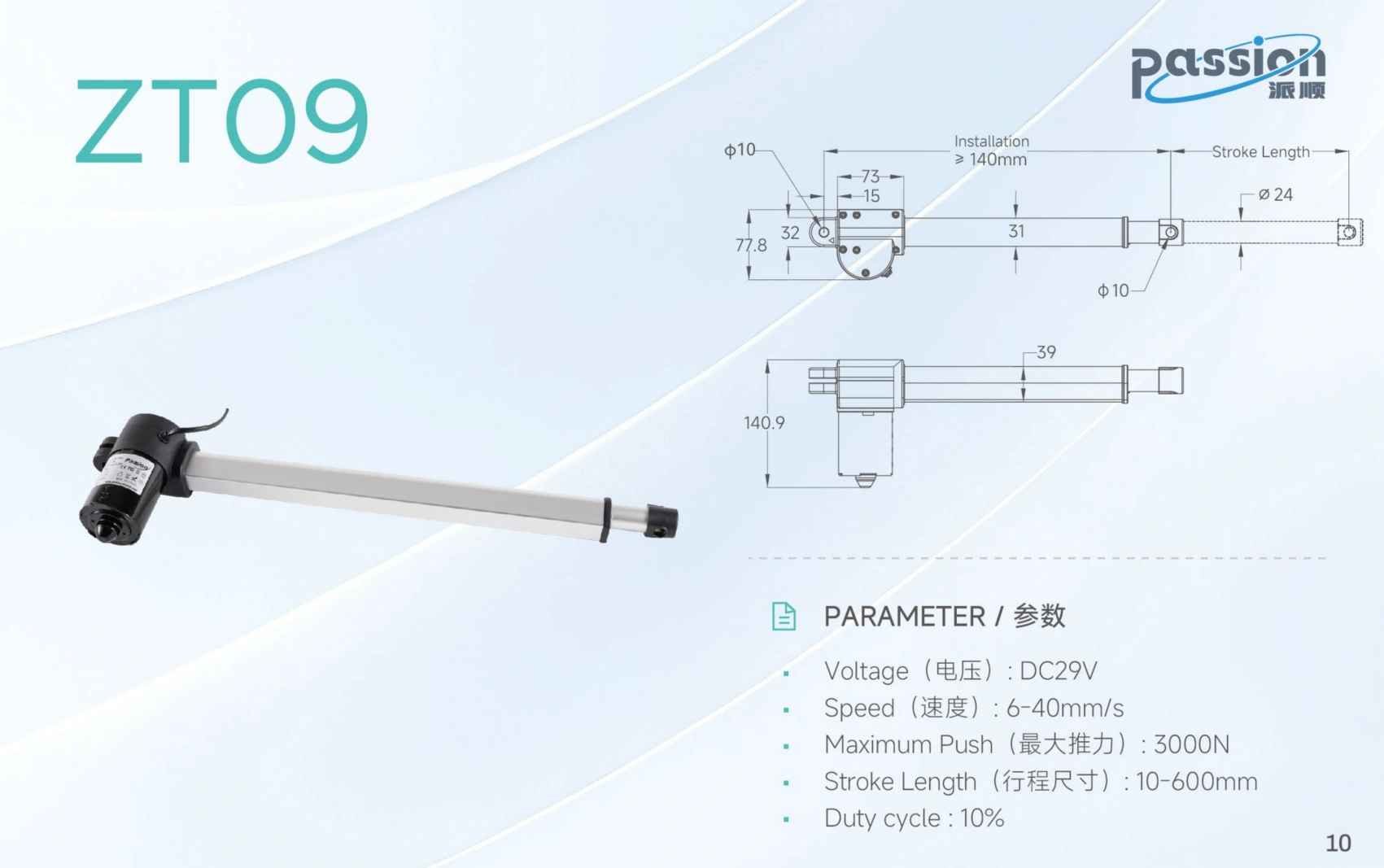
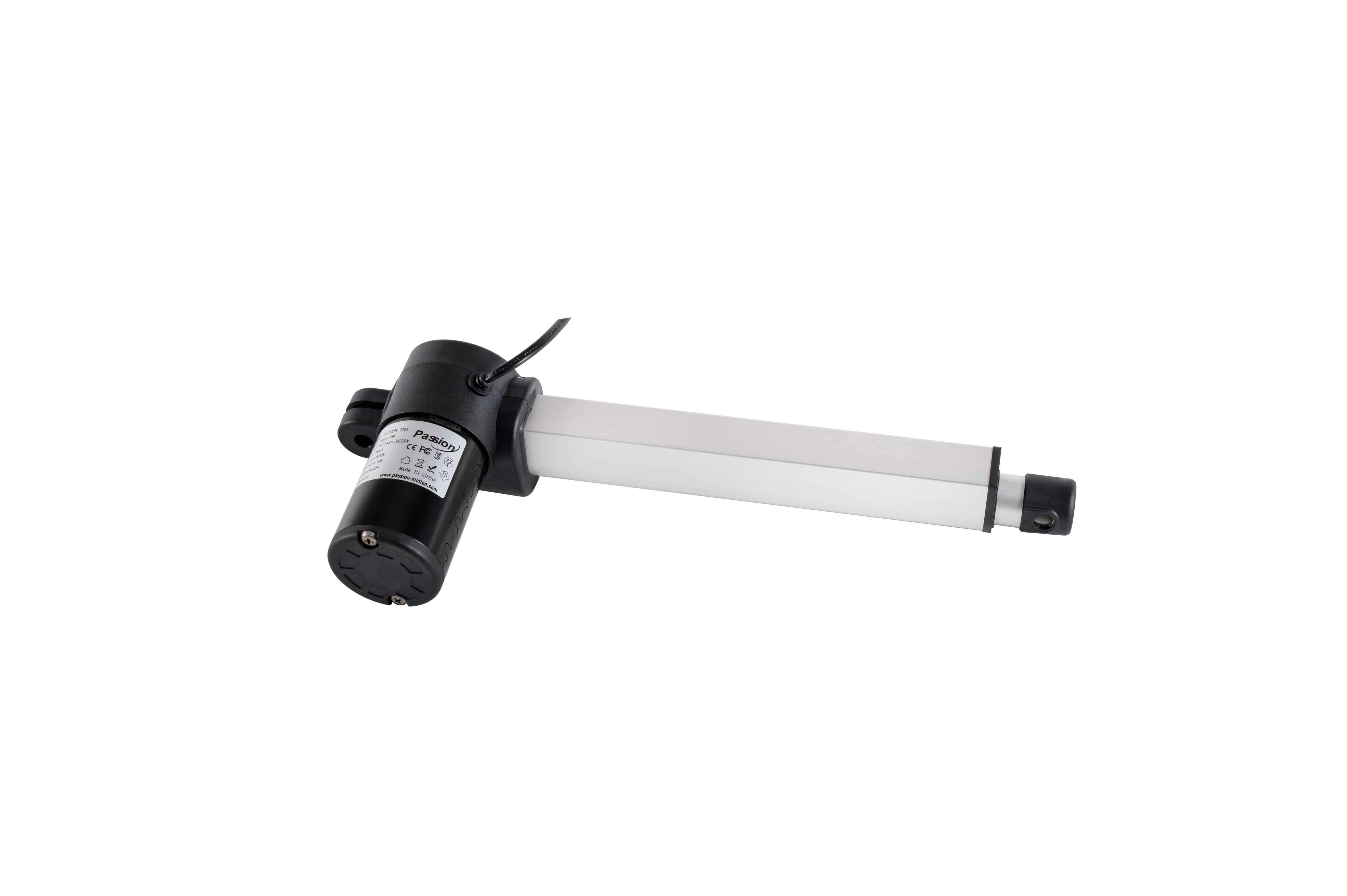
Two motion devices can provide similar travel yet differ materially in installed envelope, mounting, and side-load tolerance.
This is especially important in compact equipment. A unit may provide sufficient travel but still be unusable because its retracted length, motor housing, connector exit, or mounting geometry conflicts with the machine structure.
A good CAD check asks two questions:
- Can the mechanism achieve the required motion?
- Can the motion device physically exist in every position without collision or overconstraint?
Step 3: Convert “fast enough” into a cycle requirement
Speed should be defined in the context of the actual motion cycle.
Useful inputs include:
- required travel distance;
- target move time;
- acceleration and deceleration expectations;
- time spent under load;
- dwell time;
- number of cycles per hour;
- expected daily cycle count;
- simultaneous-axis operation.
A higher no-load speed is not automatically better. Speed, force, gearing, current, noise, control stability, and thermal load can trade against one another.
For a user-facing lift, smooth and quiet motion may matter more than minimum cycle time. For an industrial process, throughput may dominate. For pressing, the approach speed and working portion of the stroke may need different profiles.
Step 4: Define duty cycle and the thermal operating case
Duty cycle answers how long the motion system is energized relative to its rest period, but the real engineering question is broader: what thermal condition will the device see in the actual machine?
Capture:
- run time per move;
- dwell time;
- cycles per hour;
- number of axes operating simultaneously;
- ambient temperature;
- enclosure ventilation;
- load during each part of the cycle;
- worst-case repeated operation.
A design that works for a few demonstration cycles may overheat in production if the real cycle is more demanding.
That is why prototype validation should reproduce the expected duty profile rather than only confirming that the mechanism moves once.
Step 5: Decide how much position information the machine needs
Not every motion axis needs the same level of feedback.
The application may require only:
- full extend / full retract;
- one or more preset positions;
- continuous position;
- speed measurement;
- synchronized multi-axis motion;
- repeatable process position;
- fault or following-error detection.
Those needs determine whether the architecture can remain simple or must include feedback and closed-loop control.
Possible feedback concepts include Hall pulses, potentiometers, encoders, limit inputs, or other position-sensing methods. The important point is not the sensor name alone. The control system must understand the signal, scaling, direction, reference behavior, and fault state.
For projects where electrical and feedback interfaces are already known, system compatibility review can be used to verify that the selected components form a coherent system.
Step 6: Check holding, backdriving, and power-off behavior
A vertical or body-supporting axis should never be selected only from moving force.
Ask:
- Does the load need to remain in position when power is off?
- Is mechanical self-locking required?
- Is a brake required?
- What happens if the drive is disabled?
- Can the mechanism backdrive under load?
- Is a controlled descent required?
- Is a secondary mechanical restraint required by the machine risk assessment?
These questions can be more important than top speed.
For AV lifts and industrial vertical motion, the design should also consider center-of-gravity shifts and guide loading throughout the full travel.
Step 7: Keep side loads out of the screw whenever possible
Many linear motion devices are designed primarily for axial force. Machine structure should manage side loads, moments, and misalignment unless the selected product is specifically designed to carry them.
Check:
- guide parallelism;
- mounting-hole tolerance;
- frame deflection;
- pivot freedom;
- side-load path;
- load moment;
- binding near end positions;
- thermal expansion where relevant.
A powerful actuator cannot compensate for a poorly constrained mechanism.
This is particularly important in pressing stations, where tooling alignment and structural stiffness can affect both force application and repeatability.
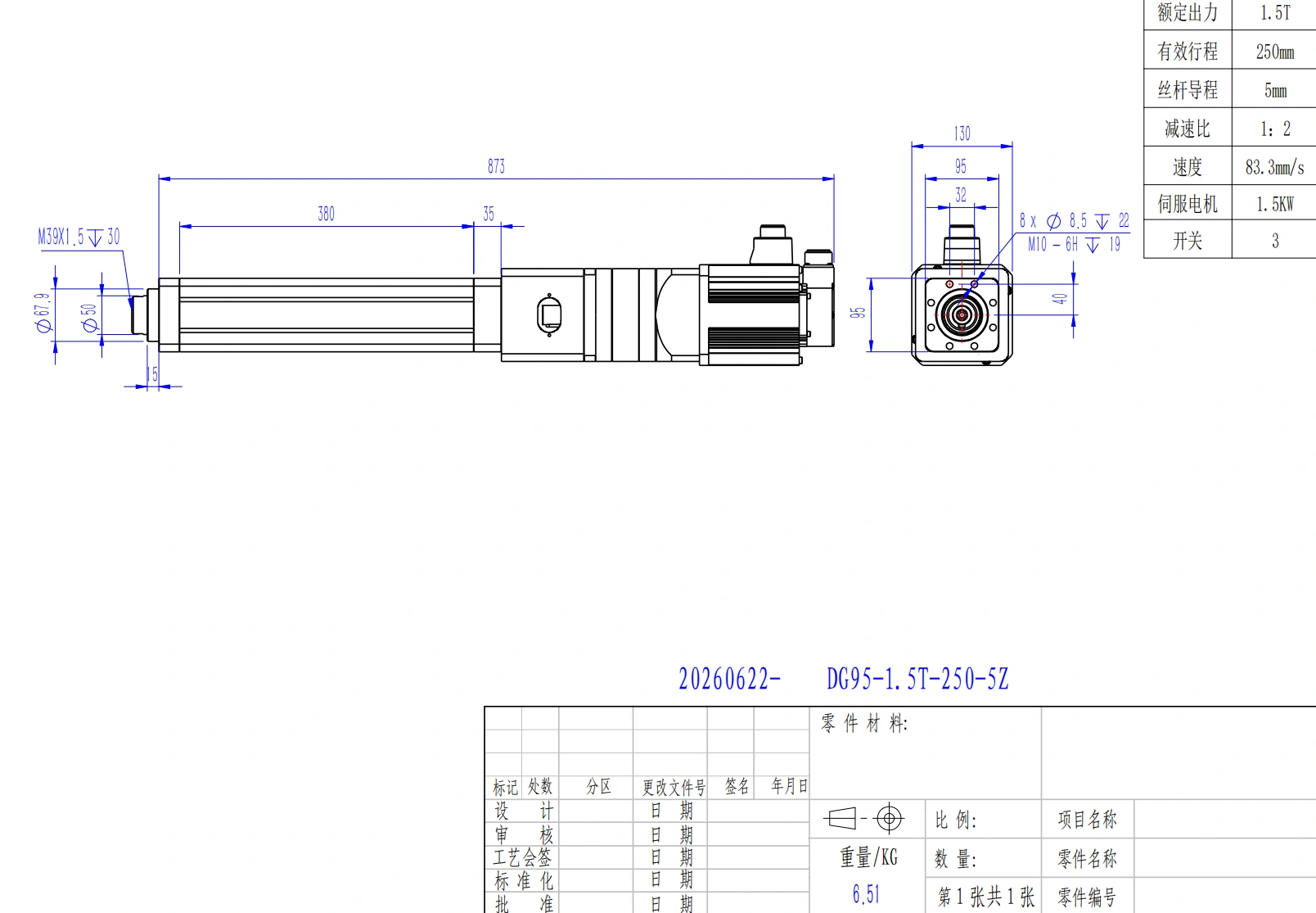
Pressing tasks should be specified around force, stiffness, repeatability, duty cycle, and feedback needs before model selection.
Step 8: Add environment, noise, and service constraints
Application requirements should include the conditions surrounding the actuator, not only motion numbers.
Examples:
- ambient temperature range;
- dust or liquid exposure;
- corrosion risk;
- washdown requirement;
- indoor/outdoor installation;
- vibration;
- acoustic target;
- cable movement;
- connector access;
- maintenance interval;
- replacement access;
- documentation and traceability.
In adjustable furniture, acoustic behavior can be a major user-experience constraint. In a factory, contamination, temperature, and service access may be more important.
The requirement should state the environment rather than assume that an enclosure label alone guarantees suitability for the complete machine.
Step 9: Treat power and controls as part of selection
Mechanical sizing is only half of the system.
Define:
- available supply architecture;
- voltage range;
- continuous and peak current budget;
- cable length and conductor size;
- number of axes;
- single or multi-channel operation;
- local or PLC control;
- feedback type;
- synchronization requirement;
- limit and interlock inputs;
- communication interface;
- reset/homing expectations.
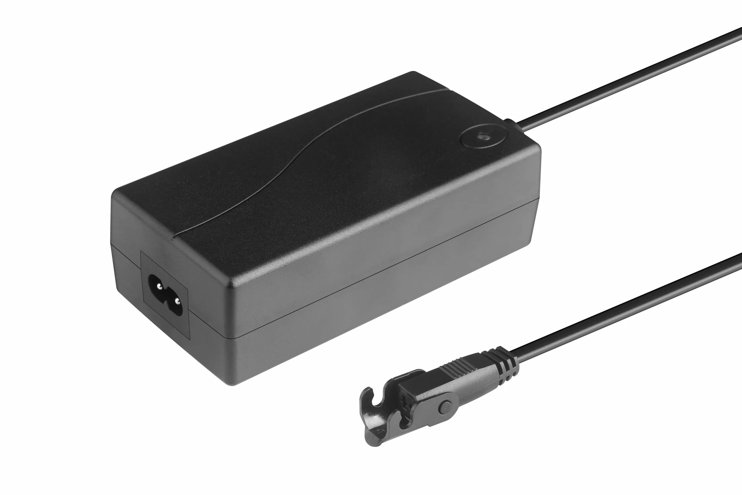
Power, current, control channels, and feedback interfaces are application requirements—not accessories to decide after mechanical sizing.
A motion component that fits mechanically but cannot be powered or controlled in the intended architecture is not a valid selection.
The product selector can help narrow candidates after these requirements are known. It should not replace the requirements-definition step.
Step 10: Validate the worst credible case before production
Prototype validation should reproduce the application, not just bench motion.
A useful validation plan includes:
- worst-case load;
- minimum and maximum supply condition;
- repeated cycle profile;
- full stroke;
- mounting tolerance;
- guide friction;
- temperature;
- cable routing;
- obstruction/fault behavior where relevant;
- power-off behavior;
- multi-axis coordination if used;
- representative noise measurement if it is a requirement;
- post-cycle inspection.
The validation record should also identify the exact hardware and control configuration tested.
Application requirements worksheet
Before requesting a quotation or approving a candidate, complete this checklist:
Mechanical
- load and load direction;
- force requirement and design margin;
- stroke;
- retracted/extended geometry;
- mounting points;
- guide arrangement;
- side-load/moment constraints;
- holding/backdrive requirement.
Motion
- target speed;
- acceleration/deceleration;
- cycle time;
- duty cycle;
- positioning/repeatability;
- number of axes;
- synchronized or independent motion.
Electrical and control
- supply architecture;
- current budget;
- command source;
- feedback;
- limits/interlocks;
- channel count;
- communication;
- fault/reset behavior.
Environment and lifecycle
- temperature;
- contamination/liquid exposure;
- noise target;
- vibration;
- expected cycles;
- service access;
- documentation;
- validation test.
When this worksheet is complete, use the Industries hub to move to the relevant commercial solution context without mixing the selection methodology with industry-page ownership.
If the project has a completed requirements sheet and needs an engineering review, send it through ServoCylMotion contact .
FAQs
What should be defined before selecting a linear motion device?
At minimum: load path, force, stroke, installed geometry, speed, duty cycle, holding behavior, feedback/position needs, mounting, environment, power, controls, and validation conditions.
Why is stroke not enough to determine fit?
Because installation depends on retracted length, mounting-point geometry, housing clearance, cable routing, and the mechanism's full motion envelope.
How do lifting and pressing requirements differ?
Lifting often emphasizes holding, backdrive behavior, load balance, and safe vertical motion. Pressing often places more emphasis on force profile, stiffness, alignment, repeatability, and process control.
When should feedback be specified?
Whenever the system must know or correct actual motion—for example intermediate positioning, repeatability, synchronized axes, presets, speed measurement, or diagnostics.
Why include duty cycle in the application sheet?
Because repeated operation creates thermal load. A device that performs one move successfully may not be suitable for the real production cycle.
What should be validated before production?
Test the exact configuration under representative worst-case load, geometry, cycle, supply, environment, and fault conditions that matter to the machine.
References
- Control Engineering — Actuators explained
- Motion Solutions — Selecting the Right Linear Actuator
- Iris Dynamics — How to Select a Linear Actuator in 6 Steps
- FAULHABER — Linear Actuator Selection Tutorial
- Teknic — How to Choose the Best Linear Actuator for Your Application
- GlobalSpec — Linear Actuators Selection Guide