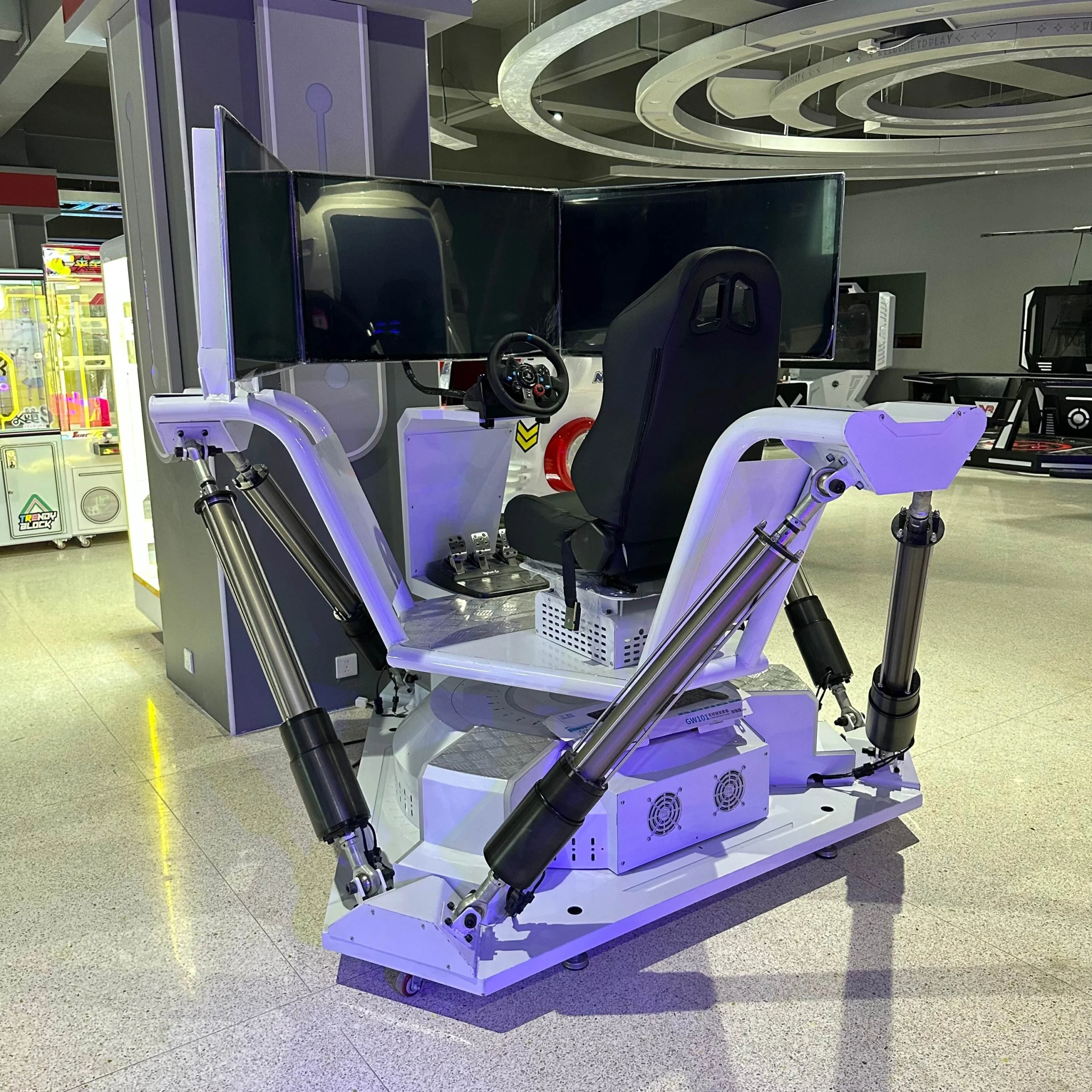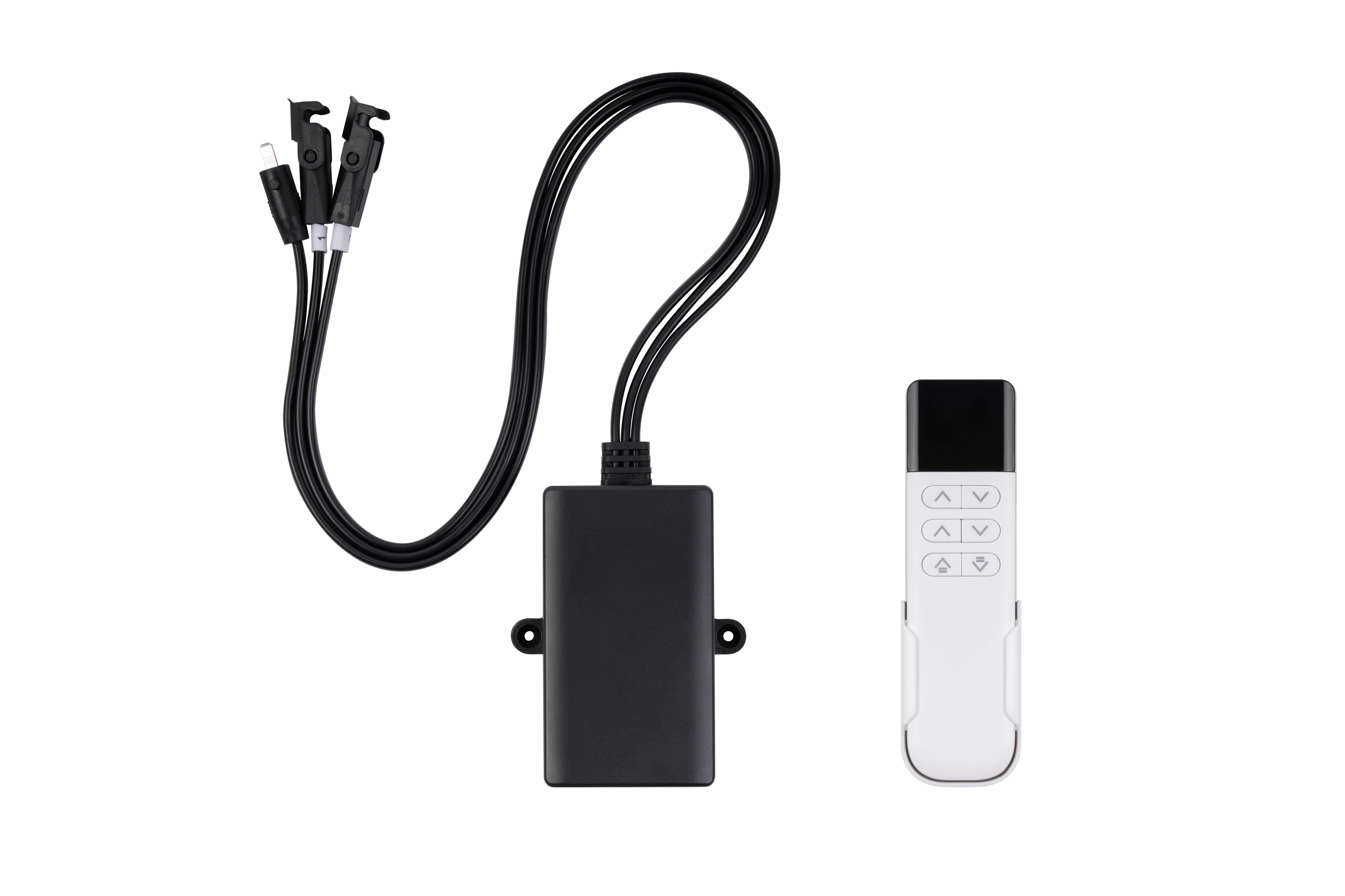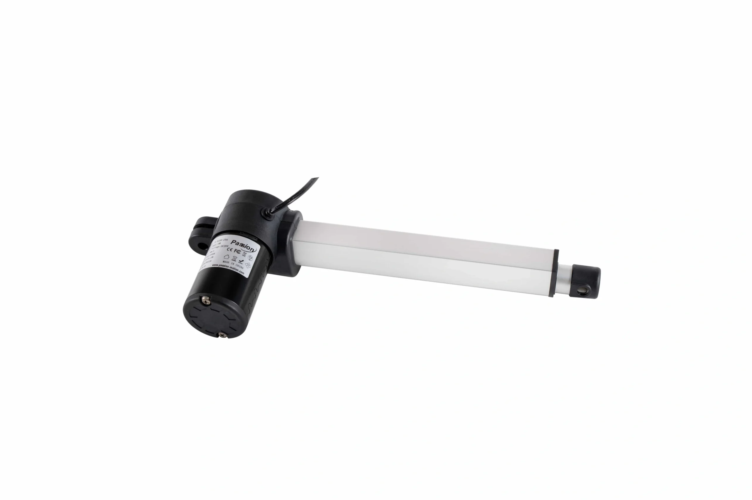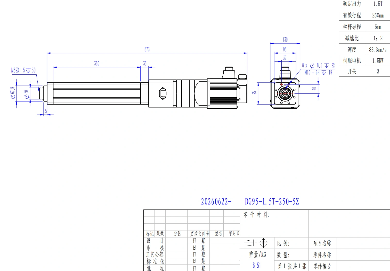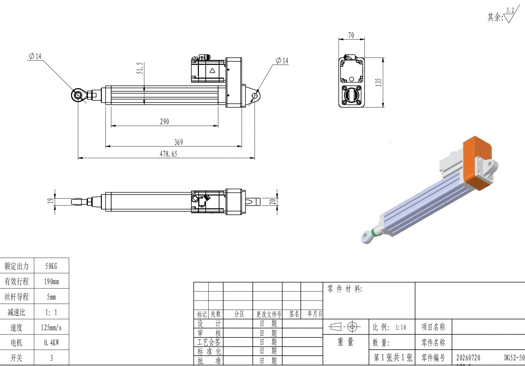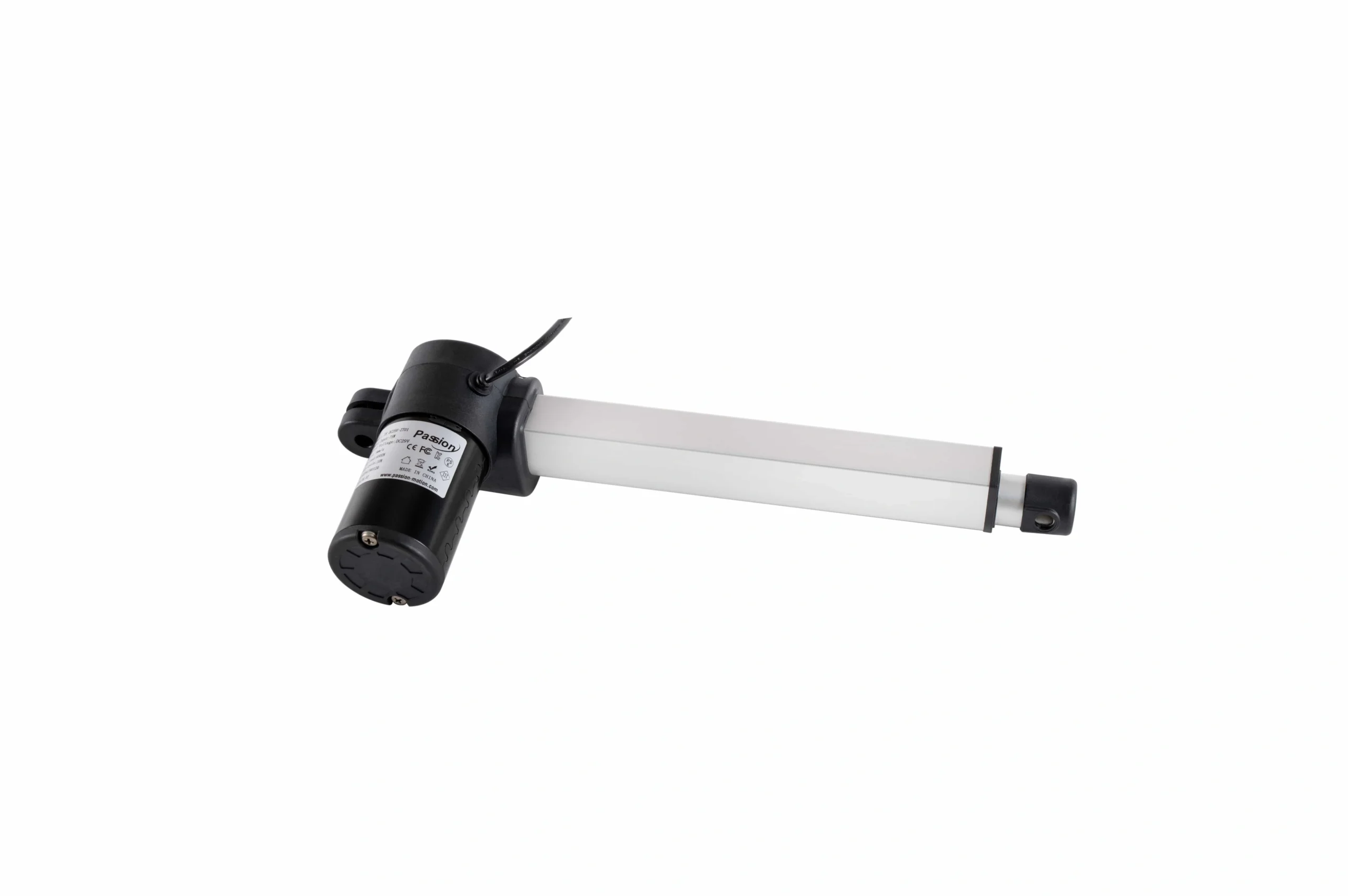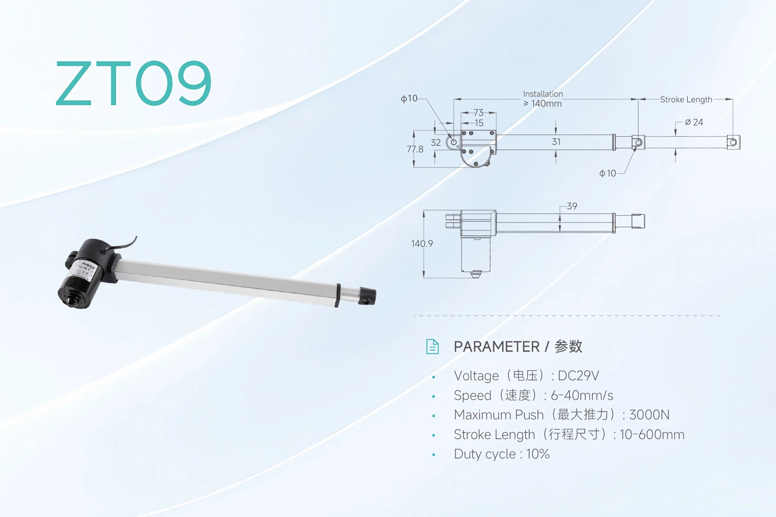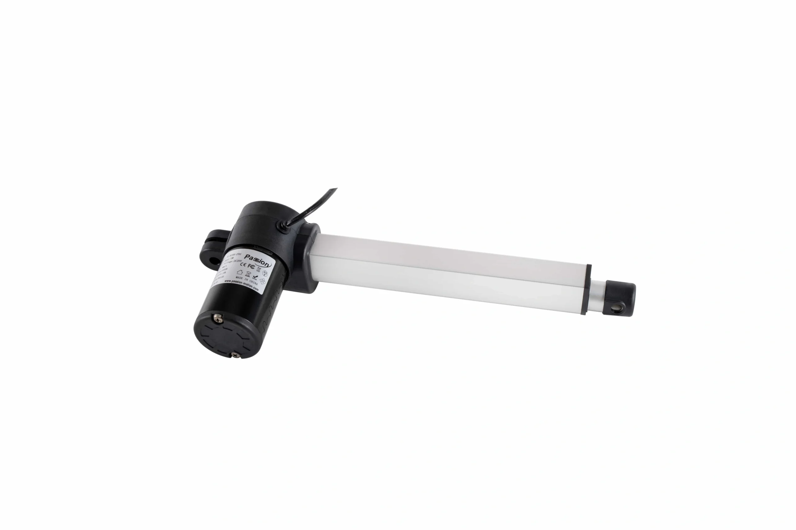
The right linear actuator is the configuration that meets the real operating point: required force at the required loaded speed, through the required travel, inside the available installation envelope, for the actual duty cycle, environment, mounting arrangement, and control method.
Selection should therefore begin with the application—not with the largest number in a catalog.
One rule prevents many early mistakes: treat published maximum values as independent boundaries until configuration-level data confirms that they can occur together. Maximum force, fastest travel, longest stroke, duty, and installation dimensions may belong to different configurations.
Quick Linear Actuator Selection Checklist
Define these inputs before comparing models:
| Selection input | What to define | Why it matters |
|---|---|---|
| Load and force | Moving load, holding load, orientation, friction, acceleration, external forces | Establishes the required operating force |
| Speed and motion | Loaded speed, move time, acceleration, dwell, reversals | Defines the real motion profile |
| Stroke and geometry | Usable travel, retracted length, extended length, mounting points, clearance | Confirms that the mechanism can physically fit and move |
| Duty and thermal conditions | Run time, rest time, cycle frequency, ambient temperature | Determines whether repeated operation is thermally feasible |
| Mounting and guidance | Orientation, alignment, side loads, moments, external guides | Prevents the actuator from becoming an unintended structural guide |
| Environment | Dust, moisture, corrosion exposure, temperature, vibration | Defines protection and material requirements to verify |
| Power and controls | Supply, controller, command method, limits, braking needs | Ensures the motion unit can operate as part of the machine |
| Feedback and precision | Position verification, repeatability, synchronization, feedback type | Defines sensing and control requirements |
| Validation | Exact data sheet, CAD drawing, operating point, test conditions | Confirms the chosen configuration rather than a family-level assumption |
If several of these inputs are still unknown, model comparison is premature.
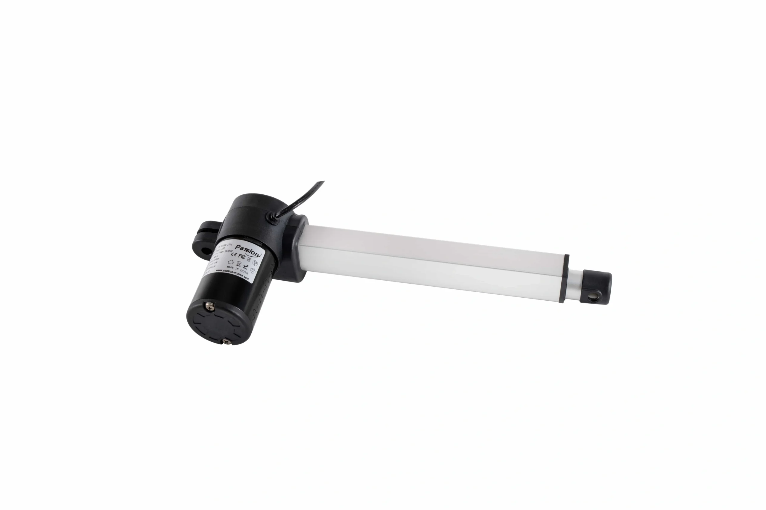
Begin selection from application requirements, then compare only configurations that can meet the same operating point.
1. Define the Real Load and Force Requirement
Start by describing what the mechanism must actually move and hold.
Payload alone is rarely enough. Depending on the machine, required force may also be affected by friction, gravity, acceleration, linkage geometry, process forces, or external resistance. A vertical lift can have different requirements from a horizontal slide carrying the same mass. A hinged lid can produce a changing mechanical advantage through the stroke.
Separate at least three questions:
- What force is required while the mechanism is moving?
- What load must be held when motion stops?
- What short-duration peaks can occur during startup, reversal, impact, or process contact?
Avoid applying one generic numerical safety factor to every project. Engineering margin should reflect uncertainty in the load model, operating conditions, shock, wear, and the consequences of undersizing.
If the mechanism includes an angled linkage, pivot, or changing lever arm, organize those conditions before model screening. The actuator sizing resource is the next step once the basic geometry and load case are known.
2. Define Loaded Speed and the Full Motion Profile
A speed value without a load condition is incomplete.
Document the required travel time or linear speed under the intended working load. Then define the rest of the motion profile:
- acceleration and deceleration expectations;
- number of starts and stops;
- dwell time at each end or intermediate position;
- reversals;
- cycle frequency;
- whether the machine stops at fixed points or moves continuously between positions.
Motor, screw, gearing, controller, and thermal behavior interact. A configuration that can generate the required force may not deliver the required travel speed under the same conditions.
When reviewing data, ask for performance at the intended operating point rather than assuming that the highest force rating and fastest catalog speed belong to one configuration.
3. Set Stroke, Then Verify Installed Geometry
Stroke answers only one question: how far the moving element can travel. It does not prove that the actuator fits the machine.
For each candidate, verify:
- required usable stroke;
- retracted installation length;
- extended length;
- center-to-center mounting distance where applicable;
- bracket and pin geometry;
- clearance around the body and moving member;
- space for connectors and cable routing;
- collision risk through the full motion;
- access for assembly and service.
A project can have the correct stroke and still fail because the retracted body is too long, the mounting points do not align, or another machine component enters the travel envelope.
Use the CAD and datasheet library to verify documented dimensions before releasing the mechanical design.
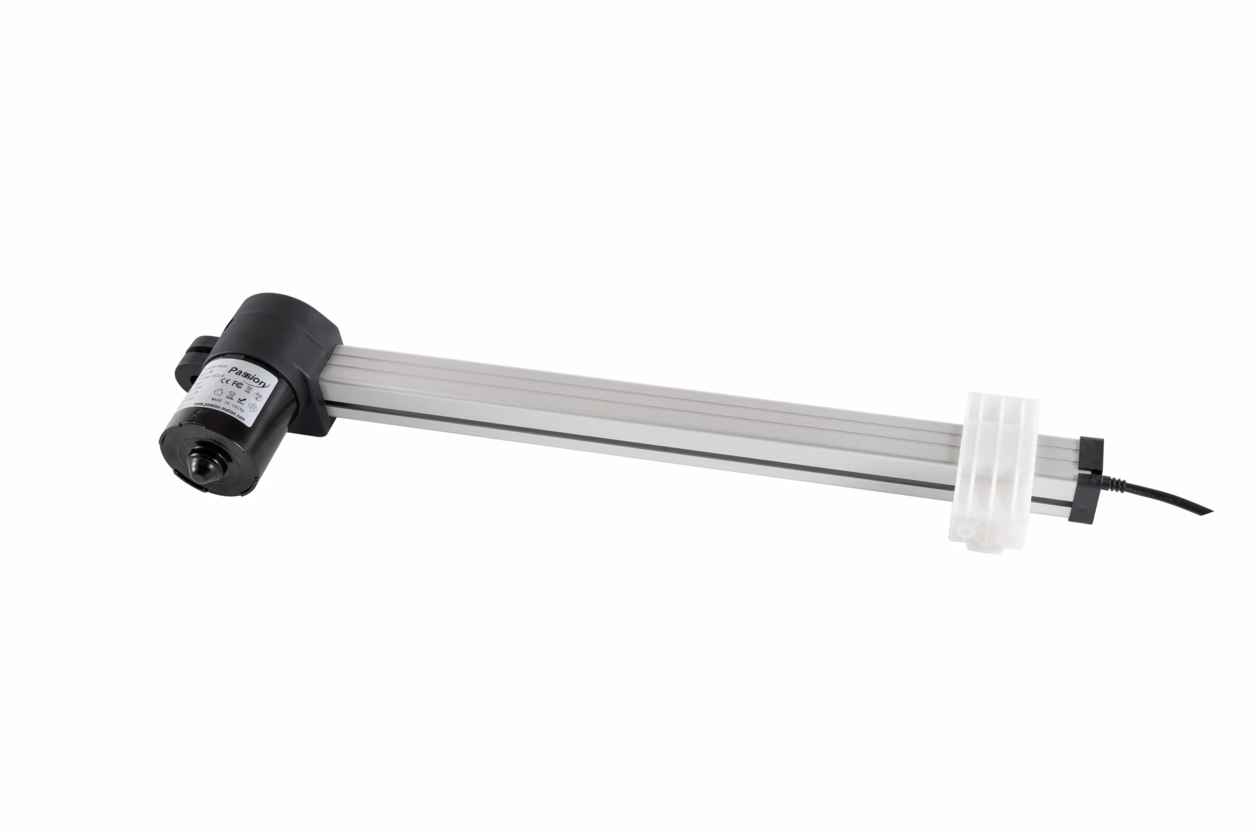
Required travel is only one dimension; mounting points, body length, clearance, and guidance also have to fit the mechanism.
4. Check Duty, Thermal Behavior, and Environment
Duty cycle is part of the operating condition, not a footnote.
Describe the application as a repeating sequence: move, stop, return, wait. Record how long each stage lasts and how often the cycle repeats. Heating depends on real load, current, motor behavior, ambient conditions, and rest time, so a peak capability does not automatically prove that repeated operation is acceptable.
Translate the environment into specific engineering checks. Instead of saying only “indoor” or “industrial,” document:
- expected temperature range;
- dust exposure;
- moisture or splash exposure;
- corrosive substances;
- washdown requirements where relevant;
- vibration or shock;
- noise limits where sound matters.
Protection ratings, materials, lubrication needs, and thermal limits should be verified for the exact configuration. Do not assume one family-wide environmental rating unless controlled documentation states it.
5. Verify Mounting, Alignment, and External Guidance
Many linear-motion failures begin as integration problems rather than motor problems.
A screw-driven or rod-style actuator is easiest to evaluate when the primary working force follows the intended axis of motion. Misalignment, lateral force, or moment loading can add stress that is not represented by a simple axial-force calculation.
During mechanical review, ask:
- Are both mounting points aligned through the full travel?
- Does the mechanism introduce a side force as it moves?
- Does an offset load create a moment?
- Is the actuator expected to guide the moving structure?
- Should a rail, bearing, linkage, or other external guide carry lateral loads instead?
Do not assume that every candidate can tolerate the same side load or moment. That capability must be verified from the selected product documentation or engineering review.
6. Define Power, Control, Feedback, and Precision Needs
Mechanical fit is only part of selection.
Before finalizing a candidate, define the electrical and control behavior the machine needs:
- available supply voltage and current capacity;
- controller or motor-drive architecture;
- simple extend/retract control versus commanded positioning;
- end-of-travel detection;
- intermediate stopping requirements;
- position verification;
- repeatability expectations;
- synchronization with another axis;
- braking or holding behavior in vertical applications;
- control signals and interfaces required by the machine.
Feedback is not automatically necessary for every application. A simple two-position mechanism may need only reliable end limits, while positioning, closed-loop motion, or synchronization can require additional sensing and control.
After a candidate and control method are known, use the system compatibility resource to review actuator, controller, power, connector, and cable fit as one system.
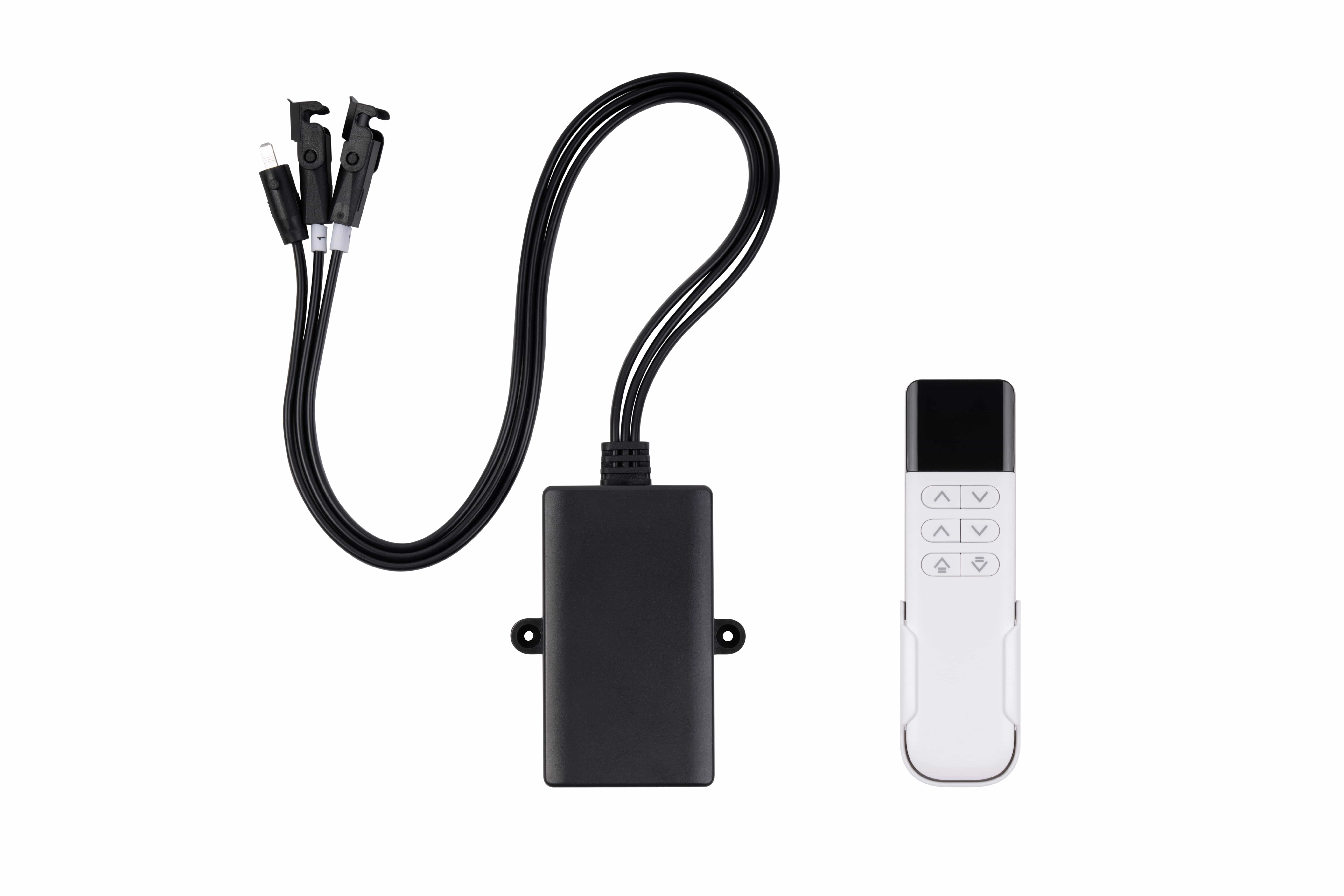
Mechanical suitability is not enough; supply, controller, command method, limits, and feedback requirements must also be compatible.
7. Compare Motion Architectures Only After Requirements Are Known
Choosing a drive technology too early reverses the engineering process.
Broadly, screw-driven systems, belt-driven axes, and direct-drive linear systems involve different tradeoffs in force, travel, speed, precision, package size, cost, stiffness, and maintenance. Within screw-driven systems, lead, efficiency, backlash, critical speed, and load capacity can also change the feasible operating envelope.
There is no universal best architecture independent of the application.
Use this sequence instead:
- define the load and motion profile;
- define stroke and installation limits;
- define duty and environment;
- define precision and control needs;
- compare only the architectures that can satisfy those conditions.
For ServoCylMotion projects, once the requirement profile is complete, review the linear actuator family rather than choosing from a technology label alone.
8. Validate the Exact Configuration Before Design Release
A family page is useful for screening. Final selection requires configuration-level confirmation.
Before design release, verify:
- the exact model or configuration;
- force at the intended loaded operating point;
- travel speed under the relevant condition;
- usable stroke;
- retracted and extended dimensions;
- mounting details;
- duty and temperature conditions;
- feedback and control options;
- electrical requirements;
- relevant environmental requirements;
- documented compatibility with the selected controller and power system.
Once the requirement profile is bounded, the product selector can narrow the available options. Use the sizing resource for preliminary calculations, then confirm the result against controlled documentation and engineering review.
For custom mounting, travel, cable, control, or configuration needs not covered by a standard option, use the OEM/ODM engineering route rather than assuming an undocumented variation is available.
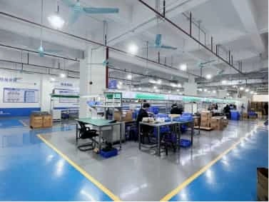
Final selection should be verified against the exact configuration, application conditions, and controlled product documentation.
Common Linear Actuator Selection Mistakes
Choosing from maximum force alone
Force is only one dimension of the operating point. The candidate must also satisfy loaded speed, stroke, duty, geometry, environment, and control requirements.
Combining independent maximum ratings
The largest force, fastest travel, and longest stroke shown across a family should not be treated as one guaranteed configuration. Verify the exact combination.
Ignoring retracted length
A correct stroke does not guarantee fit. Body length, mounting centers, connector position, and service clearance can be equally important.
Using the actuator as a structural guide
If the mechanism creates lateral forces or moments, verify whether the selected unit can tolerate them or provide external guidance.
Treating duty as an afterthought
A configuration may complete one move successfully but still be unsuitable for the required repetition rate or thermal environment.
Adding feedback too late
If the machine requires positioning, verification, or synchronized movement, define those needs before choosing the controller and feedback package.
Sending an incomplete RFQ
A supplier cannot reliably review a project from force and stroke alone. A complete motion and installation brief reduces assumptions and shortens engineering review.
What to Send for Engineering Review
A useful selection brief includes:
| Input | What to provide |
|---|---|
| Motion task | Lift, push, pull, slide, tilt, clamp, position, open/close |
| Working load | Moving and holding conditions, orientation, external forces |
| Required motion | Stroke, loaded speed or move time, acceleration needs, dwell and reversals |
| Cycle | Moves per period, run time, rest time, expected operating hours |
| Geometry | Mounting points, available envelope, drawing or CAD model |
| Guidance | Rails, bearings, linkages, known side loads or moments |
| Environment | Temperature, dust, moisture, corrosion, vibration, noise constraints |
| Electrical | Available supply, controller concept, signal requirements |
| Feedback | Limits, position verification, repeatability, synchronization |
| Project context | Prototype or production stage, target quantity, schedule, customization needs |
This brief can be used to screen models, review a drawing, check system compatibility, and prepare a more useful RFQ.
Frequently Asked Questions
Can I choose a linear actuator from maximum force alone?
No. Maximum force is only one boundary. Selection should also consider required loaded speed, stroke, installed geometry, cycle, environment, mounting, and control requirements.
Are maximum force and the fastest listed speed always available together?
Not necessarily. Treat published maxima as independent until exact model or configuration data confirms that combination.
How should I define the required stroke?
Start with the mechanism’s actual travel. Then verify retracted length, extended length, mounting centers, clearance, and the full movement envelope. Stroke alone does not prove fit.
Why do alignment and side loads matter?
Loads that do not follow the intended motion axis can add stress to the actuator mechanism. Verify the selected unit’s capability and use external machine guidance when the mechanism requires it.
Do I need position feedback?
It depends on the control task. Basic end-to-end motion may use limit detection, while positioning, verification, repeatability, or synchronization can require additional feedback and closed-loop control.
When should I use a selector or sizing tool?
Use them after the application requirements are reasonably defined. A selector can narrow candidates and a sizing tool can organize preliminary calculations, but neither can replace missing information about geometry, duty, environment, or controls.
What should I send to a supplier?
Send the load case, motion profile, stroke and installation geometry, duty, environment, mounting and guidance details, electrical/control requirements, feedback needs, and project context. A drawing or CAD model is especially useful when packaging is tight.
Build the Requirement Profile Before You Pick a Model
A reliable selection process moves from application conditions to a verified configuration—not from a catalog headline to an assumption.
If you already know the load, motion, stroke, mounting envelope, duty, environment, and control requirements, send that requirement profile for engineering review. ServoCylMotion can use it to compare applicable configurations, identify missing verification points, and prepare the next technical step.
References
The following sources provide additional background on linear motion selection, sizing considerations, integration, and application review.
- Tolomatic — actuator selection steps
- Motion Control Tips — actuator selection considerations
- IAI — selection from application specifications
- SMC — actuator selection support
- Firgelli — linear motion engineering guide
- FAULHABER — linear motion selection tutorial
- Iris Dynamics — six-step linear motion selection method
- Association for Advancing Automation — choosing a linear motion solution
- Motion Solutions — selecting the right linear motion solution
- igus — choosing a linear motion configuration
- MISUMI — actuator selection considerations
- Teknic — linear motion selection guidance
Related engineering guides: how an electric actuator works; types of linear actuators; linear actuator sizing; static vs. dynamic load.